EP0348095A2 - Störungsfreies Verfahren zur Messung der Laufzeit eines Telekommunikationsnetzwerks und Gerät zur Ausführung des Verfahrens - Google Patents
Störungsfreies Verfahren zur Messung der Laufzeit eines Telekommunikationsnetzwerks und Gerät zur Ausführung des Verfahrens Download PDFInfo
- Publication number
- EP0348095A2 EP0348095A2 EP89306019A EP89306019A EP0348095A2 EP 0348095 A2 EP0348095 A2 EP 0348095A2 EP 89306019 A EP89306019 A EP 89306019A EP 89306019 A EP89306019 A EP 89306019A EP 0348095 A2 EP0348095 A2 EP 0348095A2
- Authority
- EP
- European Patent Office
- Prior art keywords
- communicating means
- propagation delay
- delay
- time
- line
- Prior art date
- Legal status (The legal status is an assumption and is not a legal conclusion. Google has not performed a legal analysis and makes no representation as to the accuracy of the status listed.)
- Granted
Links
Images


Classifications
-
- H—ELECTRICITY
- H04—ELECTRIC COMMUNICATION TECHNIQUE
- H04B—TRANSMISSION
- H04B3/00—Line transmission systems
- H04B3/02—Details
- H04B3/46—Monitoring; Testing
- H04B3/462—Testing group delay or phase shift, e.g. timing jitter
-
- H—ELECTRICITY
- H04—ELECTRIC COMMUNICATION TECHNIQUE
- H04J—MULTIPLEX COMMUNICATION
- H04J3/00—Time-division multiplex systems
- H04J3/02—Details
- H04J3/06—Synchronising arrangements
- H04J3/0635—Clock or time synchronisation in a network
- H04J3/0682—Clock or time synchronisation in a network by delay compensation, e.g. by compensation of propagation delay or variations thereof, by ranging
Definitions
- This invention generally relates to methods and apparatus for measuring the propagation delay of a telecommunications network. More particularly, this invention relates to non-interfering methods and apparatus for measuring propagation delay between communicating devices by using the edge of the data communications passband for sending and receiving signals meant for the measurement of propagation delay.
- a method for measuring the propagation delay of an unconditioned data communication line generally comprises:
- the propagation delay for a particular secondary channel frequency is preferably determined by subtracting a correction factor from the round trip delay (loop time minus known fixed delays).
- round trip or one way delay distortion may be determined from a look-up table which relates distance ranges to distortion delay relative to a middle frequency.
- An approximate distance between the communicating means from which a distance range is chosen is obtained from the difference of the measured loop time and the known fixed delays of the communicating means.
- the propagation delay is then determined by subtracting the known fixed delays and the round trip delay distortion time from the determined loop time, and dividing by two.
- a source unit transmits over a secondary (diagnostic) channel of a line a known signal (typically a "space" comprised of all zeros or all ones) to a target unit.
- the target is arranged to loop back at 25a the known signal to the source, thereby establishing the integrity of the loop.
- the source sends a known data pattern signal (e.g. reversals with data changing states at known intervals) over the secondary channel.
- the source With the target looping back at 35a the data pattern signal, the source will at 40 ⁇ a be able to receive back the pattern and record the instants in time that the changes in the state took place. Knowing the time at which each change in state of the data was transmitted, a determination of the average total signal propagation delay (hereinafter referred to as the " loop time”) my be calculated at 50 ⁇ a.
- the communication of the known data pattern signal is preferably conducted over a secondary channel (i.e. at a frequency at the edge of the passband) of the line.
- a secondary channel i.e. at a frequency at the edge of the passband
- extra delay is encountered which will not be found in communications occurring over the midband frequencies of the unconditioned line.
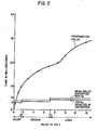
- Figure 2 which was compiled from information set forth in the End Office Connection Survey Bell System Technical Journal, November 1984 (pages 20 ⁇ 78-20 ⁇ 87), this extra delay is a function both of the frequency of the secondary channel frequency as well as the distance between the communicating source and target.
- the mean envelope delay distortion of a 330 ⁇ Hz signal relative to a middle band frequency of approximately 170 ⁇ 0 ⁇ Hz is approximately 3 milliseconds.
- the mean envelope delay for the 330 ⁇ Hz signal is approximately 3.5 milliseconds, while for long connections (>720 ⁇ miles), the mean envelope delay is approximately 4.5 milliseconds.
- the mean envelope delay relative to the middle band frequency of 170 ⁇ 0 ⁇ Hz will be different.
- the mean envelope delays for short, medium and long connections are 3.6, 4.3 and 5.0 ⁇ milliseconds respectively.
- the mean envelope delays set forth in Figure 2 are shown as step functions depending on the group into which the line distance falls (i.e. short, middle or long). However, if desired, additional groups of distances could be added and more points plotted on Figure 2. Indeed, a curve of mean envelope delay versus line distance could determined for any particular secondary channel frequency used.
- a preliminary determination of line distance must be had before a determination of envelope distortion delay may be determined.
- the known fixed delay of the communicating means is subtracted from the loop time found at 50 ⁇ a.
- the loop time minus the fixed delays provides a rough estimate of the line distance as a rough relationship of loop time to line distance exists. As seen in figure 2, for the first 180 ⁇ -20 ⁇ 0 ⁇ miles, approximately one millisecond of delay is added for each twenty miles; from 20 ⁇ 0 ⁇ -720 ⁇ miles, approximately one millisecond of delay is added for each seventy miles; and after 720 ⁇ miles, approximately one millisecond of additional loop time is added for every one hundred miles of line distance.
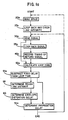
- the envelope delay (or "delay distortion time") is determined at 60 ⁇ preferably using either a look-up table, or Figure 2. Then, with the determinations of delay distortion time and loop time minus fixed delay having been made at 60 ⁇ and 53a respectively, a determination of propagation delay may be had at 70 ⁇ a.
- the propagation delay is determined by subtracting the round trip delay distortion time determined at 60 ⁇ from the difference of the loop time and fixed delays determined at 53a.
- Steps 20 ⁇ b, 30 ⁇ b, 35b, 40 ⁇ b, 50 ⁇ b, and 53b all correspond to the previously described steps 20 ⁇ a, 25a, 30 ⁇ a, 40 ⁇ a, 50 ⁇ a, and 53b such that at 53b, a determination of the loop time minus the fixed delays is made.
- the propagation delay is determined directly in Figure 1b at step 70 ⁇ b.
- the propagation delay is found by taking the loop time minus the fixed delays of the communicating means, and depending upon the value, choosing and subtracting a round trip delay distortion value.
- a delay distortion of six milliseconds is chosen and subtracted from the adjusted loop time to provide the determined propagation delay (which is not less than zero).
- a delay distortion of seven milliseconds is chosen and subtracted to provide the propagation delay.
- nine milliseconds is chosen as the delay distortion and is subtracted to provide the propagation delay.
- the propagation delay of a line may be monitored over time by repeating the method steps set forth in Figures 1a or 1b.
- steps 20 ⁇ and 25 need not be repeated. The repetition of the propagation delay measurement would provide the user with an indication as to whether a communication is being rerouted during transmission.
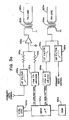
- FIGS. 3a and 3b where like numerals are indicative of like parts, the means for conducting the steps of Figures 1a and 1b are broadly shown and basically comprise front ends 10 ⁇ 0 ⁇ a and 10 ⁇ 0 ⁇ b to modems (not shown). While front ends 10 ⁇ 0 ⁇ a and 10 ⁇ 0 ⁇ b are not identical as shown , those skilled in the art will appreciate that it might be beneficial for all modems to incorporate the features of both the master and slave modems.
- primary data which has been modulated by a modem is high pass filtered at 10 ⁇ 2a to clear the sidebands which would fall into the 30 ⁇ 0 ⁇ -40 ⁇ 0 ⁇ Hz range of the secondary channel.
- a microprocessor 110 ⁇ a such as a Motorola 680 ⁇ 9, having an associated timing source 10 ⁇ 4a and ROM 10 ⁇ 6a is provided and arranged to send data patterns (signals) as discussed with reference to Figures 1a and 1b.
- the data signals are then converted to FSK signals at the desired frequencies by and FSK signal generator 112a such as and XR220 ⁇ 6 manufactured by Exar Corp.
- the primary data signal and the secondary FSK data signal are summed by a summing amplifier 115a and resistors 116a and 118a.
- the resultant composite signal is then transmitted over the data communication line 120 ⁇ a via transformer 122a.
- the front end 10 ⁇ 0 ⁇ b of the looping modem receives the composite transmitted signal at transformer 125b.
- the composite transmitted signal is then split.
- One path is high pass filtered at 130 ⁇ b to provide the primary data signals, and the other path is low pass filtered at 132b to provide the secondary data signal.
- the FSK secondary data signal is then demodulated via a phase locked loop circuit 134b such as and XR2211 manufactured by Exar Corp.
- the resultant digital data is then received by microprocessor 110 ⁇ b.
- microprocessor 110 ⁇ b will have set loopback switch 140 ⁇ (together with gain adjustment as required) to accomplish the same, and will have set switch 141 to cut off any secondary signals being received from the FSK transmit 112b.
- the secondary signals originally forwarded from modem front end 10 ⁇ 0 ⁇ a will be looped back via resistor 118b, and summed by summing amplifier 115b together with primary signals which have been high pass filtered at 10 ⁇ 2b to filter out sidebands which would fall in the secondary channel frequency range.
- the composite signal is then transmitted via transformer 122b, and line 120 ⁇ b back to the front end 10 ⁇ 0 ⁇ a of the transmitting modem.
- the composite primary and secondary signal is received by transformer 125a and again split.
- One path is high pass filtered at 130 ⁇ a to provide the primary signal while the other is low pass filtered at 132a to provide the secondary channel signal which is demodulated by the phase lock loop 134a and sent to microprocessor 10 ⁇ 0 ⁇ a.
- the receipt of the signal stops a counter in microprocessor 10 ⁇ 0 ⁇ a, which, with the help of oscillator 10 ⁇ 4a, had been timing the loop time between the sending and receipt of the same.
- the microprocessor 110 ⁇ a with the use of ROM 10 ⁇ 6a which preferably stores at least look-up tables regarding delay distortion time, may then conduct the necessary calculations for a determination of propagation delay.
- non-interfering average frequency of 330 ⁇ Hz was chosen as the preferred frequency for conducting the measurement, it will be appreciated that other frequencies could be chosen, provided the delay distortion time is taken into account for the chosen frequency when making the propagation delay determination.
- the choice of means for finding the delay distortion times could vary form loop-up charts or tables, to dedicated circuitry depending on the loop time or loop time minus fixed communication means delays, to graphs, and to other available means in the art.
- the provided circuitry for conducting the propagation delay measurement could easily be changed to various equivalents as would be known to those skilled in the art.
Landscapes
- Engineering & Computer Science (AREA)
- Computer Networks & Wireless Communication (AREA)
- Signal Processing (AREA)
- Monitoring And Testing Of Transmission In General (AREA)
Applications Claiming Priority (2)
| Application Number | Priority Date | Filing Date | Title |
|---|---|---|---|
| US206514 | 1988-06-14 | ||
| US07/206,514 US4845735A (en) | 1988-06-14 | 1988-06-14 | Non-interfering method for measuring propagation delay of telecommunications network and apparatus for accomplishing same |
Publications (3)
| Publication Number | Publication Date |
|---|---|
| EP0348095A2 true EP0348095A2 (de) | 1989-12-27 |
| EP0348095A3 EP0348095A3 (de) | 1991-05-02 |
| EP0348095B1 EP0348095B1 (de) | 1994-08-31 |
Family
ID=22766738
Family Applications (1)
| Application Number | Title | Priority Date | Filing Date |
|---|---|---|---|
| EP89306019A Expired - Lifetime EP0348095B1 (de) | 1988-06-14 | 1989-06-14 | Störungsfreies Verfahren zur Messung der Laufzeit eines Telekommunikationsnetzwerks und Gerät zur Ausführung des Verfahrens |
Country Status (5)
| Country | Link |
|---|---|
| US (1) | US4845735A (de) |
| EP (1) | EP0348095B1 (de) |
| AU (1) | AU607616B2 (de) |
| CA (1) | CA1321413C (de) |
| DE (1) | DE68917806T2 (de) |
Cited By (3)
| Publication number | Priority date | Publication date | Assignee | Title |
|---|---|---|---|---|
| EP0521197A1 (de) * | 1991-06-04 | 1993-01-07 | ALCATEL BELL Naamloze Vennootschap | Verfahren zur Messung der Zeitverzögerung einer Entzerrung in einem Übertragungssystem und zugehöriges Übertragungssystem |
| EP0585087A1 (de) * | 1992-08-24 | 1994-03-02 | AT&T Corp. | Abstandmessungsverfahren in einem TDMA-System, eines mehrspannungs-baumartigen optischen Netzes |
| US5353285A (en) * | 1991-12-05 | 1994-10-04 | Alcatel N.V. | Time slot management system |
Families Citing this family (10)
| Publication number | Priority date | Publication date | Assignee | Title |
|---|---|---|---|---|
| US5247464A (en) * | 1989-05-25 | 1993-09-21 | Digital Equipment Corporation | Node location by differential time measurements |
| JPH03267775A (ja) * | 1990-03-19 | 1991-11-28 | Fujitsu Ltd | 集積回路におけるループ試験方式 |
| JP2526496B2 (ja) * | 1993-07-21 | 1996-08-21 | 日本電気株式会社 | 移動通信システム |
| US5422876A (en) * | 1993-09-07 | 1995-06-06 | Southwestern Bell Technology Resources, Inc. | Out-of-band loopback control scheme |
| US5555285A (en) * | 1995-03-30 | 1996-09-10 | Westell Incorporated | Multi-variate system having an intelligent telecommunications interface with automatic adaptive delay distortion equalization (and related method) |
| US6169763B1 (en) | 1995-06-29 | 2001-01-02 | Qualcomm Inc. | Characterizing a communication system using frame aligned test signals |
| US5784406A (en) * | 1995-06-29 | 1998-07-21 | Qualcom Incorporated | Method and apparatus for objectively characterizing communications link quality |
| US5802061A (en) * | 1995-10-19 | 1998-09-01 | Cabletron Systems, Inc. | Method and apparatus for network access control with implicit ranging and dynamically assigned time slots |
| US6647246B1 (en) * | 2000-01-10 | 2003-11-11 | Industrial Technology Research Institute | Apparatus and method of synchronization using delay measurements |
| US8179879B2 (en) * | 2006-09-18 | 2012-05-15 | Pmc-Sierra Israel Ltd. | Robust ranging method |
Family Cites Families (6)
| Publication number | Priority date | Publication date | Assignee | Title |
|---|---|---|---|---|
| US2746013A (en) * | 1952-10-18 | 1956-05-15 | Bell Telephone Labor Inc | Measurement of transmission time delay |
| US3492583A (en) * | 1968-03-06 | 1970-01-27 | Automatic Elect Lab | Fm system with pilot signal to measure group delay |
| US3731194A (en) * | 1971-11-10 | 1973-05-01 | Bell Telephone Labor Inc | Automatic time interval ranging circuit for delay interval measurements including uncertainty elimination |
| DE2221256C2 (de) * | 1972-04-29 | 1974-02-21 | Wandel U. Goltermann, 7410 Reutlingen | Anordnung zur Messung von Gruppenlaufzeit- und/oder Dämpfungsverzerrungen auf einer Teilstrecke einer eine Schleife bildenden Übertragungsstrecke |
| JPS54150907A (en) * | 1978-05-19 | 1979-11-27 | Fujitsu Ltd | Loop test control system |
| JPH06101737B2 (ja) * | 1986-04-14 | 1994-12-12 | 株式会社東芝 | 集線分配方式 |
-
1988
- 1988-06-14 US US07/206,514 patent/US4845735A/en not_active Expired - Lifetime
-
1989
- 1989-06-13 CA CA000602648A patent/CA1321413C/en not_active Expired - Fee Related
- 1989-06-14 AU AU36316/89A patent/AU607616B2/en not_active Ceased
- 1989-06-14 DE DE68917806T patent/DE68917806T2/de not_active Expired - Fee Related
- 1989-06-14 EP EP89306019A patent/EP0348095B1/de not_active Expired - Lifetime
Cited By (3)
| Publication number | Priority date | Publication date | Assignee | Title |
|---|---|---|---|---|
| EP0521197A1 (de) * | 1991-06-04 | 1993-01-07 | ALCATEL BELL Naamloze Vennootschap | Verfahren zur Messung der Zeitverzögerung einer Entzerrung in einem Übertragungssystem und zugehöriges Übertragungssystem |
| US5353285A (en) * | 1991-12-05 | 1994-10-04 | Alcatel N.V. | Time slot management system |
| EP0585087A1 (de) * | 1992-08-24 | 1994-03-02 | AT&T Corp. | Abstandmessungsverfahren in einem TDMA-System, eines mehrspannungs-baumartigen optischen Netzes |
Also Published As
| Publication number | Publication date |
|---|---|
| CA1321413C (en) | 1993-08-17 |
| EP0348095A3 (de) | 1991-05-02 |
| DE68917806T2 (de) | 1995-04-06 |
| AU607616B2 (en) | 1991-03-07 |
| AU3631689A (en) | 1989-12-21 |
| US4845735A (en) | 1989-07-04 |
| DE68917806D1 (de) | 1994-10-06 |
| EP0348095B1 (de) | 1994-08-31 |
Similar Documents
| Publication | Publication Date | Title |
|---|---|---|
| US4845735A (en) | Non-interfering method for measuring propagation delay of telecommunications network and apparatus for accomplishing same | |
| KR920004132B1 (ko) | 패킷화 앙상블 모뎀 | |
| AU599552B2 (en) | Satellite-based vehicle communication/position determination system | |
| JP3694023B2 (ja) | アナログセルラシステムで使用するための位置決定方法 | |
| AU692628B2 (en) | Signalling techniques and device for high speed data transmission over voiceband channels | |
| AU663442B2 (en) | Method and apparatus for transmission path delay measurements using adaptive demodulation | |
| US4688210A (en) | Method of and arrangement for synchronizing the receiver arrangements in a digital multiplex transmission system | |
| EP1363435A2 (de) | Schätzung der Versätze von Träger- und Abtastfrequenz in einem Mehrträgerempfänger | |
| CA2305586A1 (en) | Positioning system for digital telephone networks | |
| US3920935A (en) | Method for measuring the frequency-dependent attenuation of a telecommunications line, especially a two-wire line | |
| KR850004366A (ko) | 텔레페이징 시스템 및 그 방법 | |
| EP0021544A1 (de) | Vorrichtung zur Fernüberprüfung eines Modems mit einer von der Sendegeschwindigkeit abweichenden Empfangsgeschwindigkeit | |
| JPH08139642A (ja) | 無線装置 | |
| US4982446A (en) | Bit synchronization for optical networks | |
| GB2252882A (en) | Optical time division multiple access ranging | |
| US5397992A (en) | Measuring a circuit delay | |
| US3706854A (en) | Performance monitor unit for frequency multiplexed hf modems | |
| Ridout et al. | Choice of multi-channel telegraph systems for use on HF radio links | |
| JPS6223156Y2 (de) | ||
| Fowler et al. | Assessment of effects of delay distortion in data systems | |
| WO1993015563A1 (en) | Test signal transmission between stations for group delay measurement | |
| JPS601931A (ja) | Scpc通信用受信装置 | |
| JPS5947904B2 (ja) | 二重伝送通信方式 | |
| JPS6237576B2 (de) | ||
| JPH04271631A (ja) | ディジタル無線通信システム |
Legal Events
| Date | Code | Title | Description |
|---|---|---|---|
| PUAI | Public reference made under article 153(3) epc to a published international application that has entered the european phase |
Free format text: ORIGINAL CODE: 0009012 |
|
| AK | Designated contracting states |
Kind code of ref document: A2 Designated state(s): DE ES FR GB IT |
|
| PUAL | Search report despatched |
Free format text: ORIGINAL CODE: 0009013 |
|
| AK | Designated contracting states |
Kind code of ref document: A3 Designated state(s): DE ES FR GB IT |
|
| 17P | Request for examination filed |
Effective date: 19911016 |
|
| 111Z | Information provided on other rights and legal means of execution |
Free format text: DE ES FR GB IT |
|
| 17Q | First examination report despatched |
Effective date: 19930322 |
|
| GRAA | (expected) grant |
Free format text: ORIGINAL CODE: 0009210 |
|
| AK | Designated contracting states |
Kind code of ref document: B1 Designated state(s): DE ES FR GB IT |
|
| PG25 | Lapsed in a contracting state [announced via postgrant information from national office to epo] |
Ref country code: IT Free format text: LAPSE BECAUSE OF FAILURE TO SUBMIT A TRANSLATION OF THE DESCRIPTION OR TO PAY THE FEE WITHIN THE PRE;WARNING: LAPSES OF ITALIAN PATENTS WITH EFFECTIVE DATE BEFORE 2007 MAY HAVE OCCURRED AT ANY TIME BEFORE 2007. THE CORRECT EFFECTIVE DATE MAY BE DIFFERENT FROM THE ONE RECORDED.SCRIBED TIME-LIMIT Effective date: 19940831 Ref country code: ES Free format text: THE PATENT HAS BEEN ANNULLED BY A DECISION OF A NATIONAL AUTHORITY Effective date: 19940831 |
|
| REF | Corresponds to: |
Ref document number: 68917806 Country of ref document: DE Date of ref document: 19941006 |
|
| ET | Fr: translation filed | ||
| PLBE | No opposition filed within time limit |
Free format text: ORIGINAL CODE: 0009261 |
|
| STAA | Information on the status of an ep patent application or granted ep patent |
Free format text: STATUS: NO OPPOSITION FILED WITHIN TIME LIMIT |
|
| 26N | No opposition filed | ||
| PGFP | Annual fee paid to national office [announced via postgrant information from national office to epo] |
Ref country code: GB Payment date: 20010606 Year of fee payment: 13 |
|
| PGFP | Annual fee paid to national office [announced via postgrant information from national office to epo] |
Ref country code: FR Payment date: 20010629 Year of fee payment: 13 |
|
| PGFP | Annual fee paid to national office [announced via postgrant information from national office to epo] |
Ref country code: DE Payment date: 20010828 Year of fee payment: 13 |
|
| REG | Reference to a national code |
Ref country code: GB Ref legal event code: IF02 |
|
| PG25 | Lapsed in a contracting state [announced via postgrant information from national office to epo] |
Ref country code: GB Free format text: LAPSE BECAUSE OF NON-PAYMENT OF DUE FEES Effective date: 20020614 |
|
| PG25 | Lapsed in a contracting state [announced via postgrant information from national office to epo] |
Ref country code: DE Free format text: LAPSE BECAUSE OF NON-PAYMENT OF DUE FEES Effective date: 20030101 |
|
| GBPC | Gb: european patent ceased through non-payment of renewal fee |
Effective date: 20020614 |
|
| PG25 | Lapsed in a contracting state [announced via postgrant information from national office to epo] |
Ref country code: FR Free format text: LAPSE BECAUSE OF NON-PAYMENT OF DUE FEES Effective date: 20030228 |
|
| REG | Reference to a national code |
Ref country code: FR Ref legal event code: ST |