EP0348082B1 - Wischlappen-Auswringeinheit - Google Patents
Wischlappen-Auswringeinheit Download PDFInfo
- Publication number
- EP0348082B1 EP0348082B1 EP89305865A EP89305865A EP0348082B1 EP 0348082 B1 EP0348082 B1 EP 0348082B1 EP 89305865 A EP89305865 A EP 89305865A EP 89305865 A EP89305865 A EP 89305865A EP 0348082 B1 EP0348082 B1 EP 0348082B1
- Authority
- EP
- European Patent Office
- Prior art keywords
- bucket
- roller
- toggle
- lever
- mopping unit
- Prior art date
- Legal status (The legal status is an assumption and is not a legal conclusion. Google has not performed a legal analysis and makes no representation as to the accuracy of the status listed.)
- Expired - Lifetime
Links
- 230000015572 biosynthetic process Effects 0.000 claims description 4
- 238000005755 formation reaction Methods 0.000 claims description 4
- 238000010276 construction Methods 0.000 description 3
- 238000004519 manufacturing process Methods 0.000 description 3
- 235000004443 Ricinus communis Nutrition 0.000 description 2
- 240000000528 Ricinus communis Species 0.000 description 2
- 238000006243 chemical reaction Methods 0.000 description 2
- 230000006835 compression Effects 0.000 description 1
- 238000007906 compression Methods 0.000 description 1
- 230000001419 dependent effect Effects 0.000 description 1
- 230000000994 depressogenic effect Effects 0.000 description 1
- 239000002991 molded plastic Substances 0.000 description 1
- 238000000465 moulding Methods 0.000 description 1
- 230000000717 retained effect Effects 0.000 description 1
- 239000011435 rock Substances 0.000 description 1
Images

Classifications
-
- A—HUMAN NECESSITIES
- A47—FURNITURE; DOMESTIC ARTICLES OR APPLIANCES; COFFEE MILLS; SPICE MILLS; SUCTION CLEANERS IN GENERAL
- A47L—DOMESTIC WASHING OR CLEANING; SUCTION CLEANERS IN GENERAL
- A47L13/00—Implements for cleaning floors, carpets, furniture, walls, or wall coverings
- A47L13/10—Scrubbing; Scouring; Cleaning; Polishing
- A47L13/50—Auxiliary implements
- A47L13/58—Wringers for scouring pads, mops, or the like, combined with buckets
- A47L13/60—Wringers for scouring pads, mops, or the like, combined with buckets with squeezing rollers
Definitions
- the invention relates to so-called “mopping units” as used with wet mopping systems, such a unit comprising a mop bucket combined with a wringer having two squeeze rollers between which a mop can be wrung out into the bucket.
- Mopping units are in general use for the wet and damp mopping of surfaces, particularly internal floor and wall surfaces of buildings such as offices and hospitals, and in the specification of our Application No. 86304235.4 (Publication No. 0207641) we have disclosed a foot-operated mopping unit requiring the use of only one foot with a squeeze pressure, applied to a mop whilst being wrung out, which is independent of foot pressure.
- the operating mechanism for the squeeze rollers mounted at the top of the bucket comprises a toggle operating linkage which, on depression of a foot pedal at a lower level, produces relative closing movement of the squeeze rollers.
- This operating linkage comprises two pivotally interconnected toggle links which go slightly overcentre to maintain the rollers at a predetermined spacing in the wringing position.
- US-A-1905556 discloses a hand-operated wringer device in which a movable roller may be moved selectively between two fixed rollers by means of toggle linkages connected to the ends of the movable roller.
- One link of each toggle linkage has an integral extension, and the extensions are connected by a transverse handle which is swung through an arc across the top of the mechanism to move the roller.
- a mopping unit comprising a mop bucket combined with a wringer having two squeeze rollers mounted at the top of the bucket, and an operating mechanism for moving one squeeze roller towards and away from the other roller, which mechanism includes a toggle linkage connected to the movable roller and comprising two toggle links which are directly interconnected at a pivot which, when the two toggle links are aligned, is substantially coplanar with the separate rotational axes of the two rollers, and an operating lever which can be moved to bring the toggle links substantially into alignment and thereby bring the movable roller to an operative wringing position, characterised in that the operating lever comprises a foot-operated lever pivotally mounted on a lower part of the bucket and connected by a pivoted link to one of the toggle links, and in that depression of the foot-operated lever displaces the toggle links to a limit position, defined by a stop, where they are substantially aligned on opposite sides of said pivot so that they act as a direct strut to support the movable roller in
- This arrangement enables the mechanism to create high wringing pressures at the rollers, whilst the toggle links can maintain the maximum roller pressure without any flexing in the mechanism as a whole.
- the arrangement whereby the toggle linkage goes very slightly overcentre to a limit position defined by a suitable stop will accommodate manufacturing tolerances and general wear in the mechanism. It also enables the linkage to be self-maintaining in the wringing position independently of applied foot pressure so long as the wringing reaction pressure is applied to the movable roller.
- the toggle operating mechanism is duplicated at the two sides of the bucket, whereby balanced operating forces are applied to the two ends of the movable roller.
- each toggle link of each toggle linkage is directly and pivotally connected to the corresponding end of the movable roller, and pivot mountings for the movable roller attached to the connected toggle links are slidably guided in guide slots along the top edge region of the bucket.
- the other roller which will in most cases be the front roller, is preferably adjustable so that the predetermined spacing of the rollers when in the wringing position, determined by the toggle linkage, can be varied to adjust the actual squeeze pressure applied to a mop of given thickness.
- the pressure may be adjustable to wring out the mop according to whether it is to be used for wet or for damp mopping.
- said other adjustable roller may be rotatably supported between two pivotal adjustment levers respectively pivotally supported on the sides of the bucket, below the adjustable roller axis, and projecting at the top of the bucket for manual adjustment of the angular position of the levers.
- the axis of the adjustable roller may be adjustable over a shallow arc generally aligned with said guide slots in side view.
- detent means to retain each adjustment lever in adjusted angular position, comprising inter-engageable formations on that lever and the corresponding side of the bucket, the adjustment levers being mounted within the bucket and being rockable inwardly, against springs disposed between the ends of the adjustable roller and the levers, on the lever pivot mountings sufficiently to free the detent formations and allow angular adjustment of the levers.
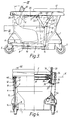
- the mopping unit illustrated comprises a moulded plastics bucket 1, shown mainly in ghost outline in Figs. 1 and 2 so that the operating mechanism is clearly visible, combined with a wringer having two rotatable squeeze rollers 2 and 3 with rotational axes X and Y disposed laterally of, and housed within, the bucket 1.
- One of the rollers 2 has the position of its axis X fixed in operation adjacent the front of the bucket 1, this position being adjustable as described hereinafter, and the other or rear roller 3 is movable by an operating mechanism 4 between the free "open” wringer position shown in full lines in the drawing figures and the "closed" operative wringer position 3′ illustrated in broken lines.
- castors 5 support the bucket 1 raised off the floor. These castors are a push-in fit in moulded sockets such as 5a and may be directly replaced, for use on smooth floors, by stand-off "glider" legs or by other floor support members.
- a foot-operated pedal 6 of the mechanism 4 is disposed below the roller 2 in a central recess 7 at the front of the bucket 1, a shrouding outer side wall 30 of the bucket being partially cut away in Fig. 3 to show the recess 7 and the mechanism 4.
- the pedal 6 is connected at its two ends between respective pedal levers 8 and 9 which extend along the two sides of the bucket 1, to which they are pivotally mounted at intermediate pivots 10 and 11.
- the pivots 10 and 11 are horizontally aligned laterally of the bucket 1.
- the operating mechanism 4, on depression of the foot pedal 6, moves the rear roller 3 to the operative position 3′ and applies a balanced squeeze pressure through the two ends of that roller, to this end the mechanism 4 employing toggle linkages 12 and 13 duplicated at opposite sides of the bucket 1.
- the pedal levers 8 and 9 are connected at pivots 14, respectively, to the lower ends of two generally upright plain pivotal links 15 and 16.
- the upper ends of the links 15 and 16 are connected, by pivots 17 and 18 respectively, to intermediate positions of rear toggle links 19 and 20 of the respective toggle linkages 12 and 13.
- the toggle links 19 and 20 are mounted at outer ends by fixed aligned pivots 21 and respectively connected at the inner ends, at aligned pivots P, to front toggle links 22 and 23 of the toggle linkages 12 and 13.
- Opposed pivot mountings 24 and 25 respectively fixed to the toggle links 22 and 23 adjacent the outer ends of these links, at the inner sides thereof, pivotally support the respective ends of the movable roller 3.
- the roller pivot mountings 24 and 25 are respectively movable along horizontal guide slots such as 26 provided at a top edge region of the bucket 1, to guide the axis Y of the movable roller 3 as it moves between the open position 3 and the operative position 3′.
- a spindle 31 of the roller 2 is mounted so as to be freely rotatable between two adjustment levers 32 and 33 which have a range of angular adjusting movement as indicated in Fig. 3.
- a series of detent projections such as 34 is moulded on the internal surface of an inner side wall 35 of the bucket 1, at each side of the latter, and these projections are selectively engageable in a moulded recess 36 in the corresponding lever 32 or 33 to retain the latter in an adjusted angular position, which determines the position of the roller axis X, relatively to a moulded pivot boss 37 on which the lever is mounted.
- Each lever 32 or 33 is retained captive on the corresponding boss 37 by a screw 38 and can rock on that boss 37, against a compression spring 39 disposed between it and the adjacent end of the roller 2, to a position in which it clears the projections 34 to allow adjusting movement of the lever.
- each toggle pivot P in the operative wringing position of mechanism 4, is substantially coplanar with the roller axes X and Y.
- toggle linkages 12 and 13 effectively act as direct struts to maintain a predetermined spacing of the rollers 2 and 3 to apply the required squeeze pressure to the inserted mop (not shown) which is wrung out as it is pulled upwardly by hand between the rollers 2 and 3. It will be appreciated that foot pressure need be applied to the pedal 6 merely for the time and to the extent necessary to hold down the bucket against the upward pull applied to pull through the mop, the squeeze pressure being determined by the toggle linkages 12 and 13 and not being dependent on foot pressure.
- the bucket 1 has a bail-type handle 41 used for carrying purposes. When not in use it pivots rearwardly to lie on top of the bucket where it does not impede the wringing out operation when the wringer rollers 2 and 3 are in use.
- the invention provides a very simple, efficient and effective roller operating mechanism of a mopping unit.
- the direct toggle struts provided by the toggle linkages 12 and 13 provide accurate and repeatable roller positioning, and a high squeeze pressure can be applied without flexing of the elements of the operating mechanism affecting operation.
- a further and manufacturing advantage of the described construction is that the upright links 15 and 16 are the only elements of the operating mechanism which need be changed to suit a different size of bucket. Thus a range of bucket sizes can employ the same mechanism components other than the simple plain links 15 and 16.
Landscapes
- Cleaning Implements For Floors, Carpets, Furniture, Walls, And The Like (AREA)
- Footwear And Its Accessory, Manufacturing Method And Apparatuses (AREA)
Claims (7)
- Wischlappenauswringeinheit, mit einem Wischlappenkübel (1) in Kombination mit einer Wringmaschine, mit zwei Wringrollen (2,3), welche oben auf dem Kübel montiert ist, und einem Betätigungsmechanismus zum Bewegen einer Wringrolle (3) auf die eine andere Rolle (2) zu oder weg von derselben, welcher Mechanismus ein Gelenkgestänge aufweist, welches mit der beweglichen Rolle verbunden ist und aus zwei Gelenkstangen (19,22) besteht, welche direkt in einem Drehpunkt (P) miteinander verbunden sind, welche, wenn die Gelenkstangen (19,22) miteinander ausgerichtet sind, im wesentlichen in der gleichen Ebene liegt wie die getrennten Drehachsen der beiden Rollen (2,3), und einem Betätigungshebel (8), welcher bewegt werden kann, um die Gelenkstangen (19,22) im wesentlichen miteinander auszurichten und dadurch die bewegliche Rolle (3) in eine Betriebswringstellung zu bringen, dadurch gekennzeichnet, dass der Betätigungshebel ein fussbetätigter Hebel (8) ist, welcher gelenkig am unteren Teil des Kübels (1) montiert ist und über eine Gelenkstange (15) mit einer (19) der Gelenkstangen verbunden ist, und, dass das Herabdrücken des fussbetätigten Hebels (8) die Gelenkstangen (19,22) in eine Endstellung bringen, welche durch einen Anschlag (19) gegeben ist, in welcher sie auf gegenüberliegenden Seiten des Drehpunktes (P) im wesentlichen miteinander ausgerichtet sind, so dass sie als direkte Stütze wirken, um die bewegliche Rolle (3) in der Wringstellung zu tragen, wobei die Gelenkstange (12) leicht überzentriert ist, wenn sie sich in dieser Endstellung befindet.
- Wischlappenauswringeinheit nach Anspruch 1, dadurch gekennzeichnet, dass der Gelenkbetätigungsmechanismus (12,13) auf beiden Seiten des Kübels vorliegt, wodurch ausgeglichene Betätigungskräfte an den beiden Enden der beweglichen Rolle (3) angelegt werden.
- Wischlappenauswringeinheit nach Anspruch 2, dadurch gekennzeichnet, dass eine Gelenkstange (22,23) jedes Gelenkgestänges direkt und schwenkbar mit dem entsprechenden Ende der beweglichen Rolle (3) verbunden ist.
- Wischlappenauswringeinheit nach Anspruch 3, dadurch gekennzeichnet, dass Drehhalterungen (24,25) für die drehbare Rolle (3), welche an den verbundenen Gelenkstangen (22,23) festgemacht sind, gleitend in Leitschlitzen (26) entlang des oberen Kantenbereiches des Kübels (1) geführt sind.
- Wischlappenauswringeinheit nach einem der Ansprüche 1 bis 4, dadurch gekennzeichnet, dass die andere Rolle (2) einstellbar ist, so dass der Abstand der Rollen in der Wringstellung, welche durch das Gelenkgestänge (12) bestimmt ist, verändert werden kann, um den Istwringdruck, der auf einen Wischlappen aufgebracht wird, zu verändern und die andere einstellbare Rolle (3) drehbar zwischen zwei Drehpunkteinstellhebeln (32,33) getragen ist, welche jeweils drehbar an den Seiten des Kübels (1) unterhalb der einstellbaren Rollenachse getragen sind und oben am Kübel zur manuellen Einstellung der Winkellage der Hebel herausragen.
- Wischlappenauswringeinheit nach den Ansprüchen 4 und 5, dadurch gekennzeichnet, dass die Achse der einstellbaren Rolle (2) über einen flachen Bogen, welcher im allgemeinen mit den beiden Leitschlitzen (26) in Seitenansicht ausgerichtet ist, einstellbar ist.
- Wischlappenauswringeinheit nach Anspruch 5 oder 6, dadurch gekennzeichnet, dass eine Feststellvorrichtung mit der jeder Einstellhebel (32,33) in der eingestellten Winkellage festgehalten werden kann, ineinander greifende Gebilde (34,36) an dem Hebel und an der entsprechenden Seite des Kübels aufweist, dass die Einstellhebel innerhalb des Kübels montiert sind und nach innen, gegen Federn (39), welche zwischen den Enden der einstellbaren Rolle (2) und den Hebeln (32,33), auf den Hebel-Drehhalterungen ausreichend ausgelenkt werden können, um die Feststellvorrichtungen (34,36) frei zu geben und die Winkeleinstellung der Hebel (32,33) zu ermöglichen.
Priority Applications (1)
| Application Number | Priority Date | Filing Date | Title |
|---|---|---|---|
| AT89305865T ATE103154T1 (de) | 1988-06-18 | 1989-06-09 | Wischlappen-auswringeinheit. |
Applications Claiming Priority (2)
| Application Number | Priority Date | Filing Date | Title |
|---|---|---|---|
| GB8814549 | 1988-06-18 | ||
| GB888814549A GB8814549D0 (en) | 1988-06-18 | 1988-06-18 | Mopping unit |
Publications (3)
| Publication Number | Publication Date |
|---|---|
| EP0348082A2 EP0348082A2 (de) | 1989-12-27 |
| EP0348082A3 EP0348082A3 (en) | 1990-11-07 |
| EP0348082B1 true EP0348082B1 (de) | 1994-03-23 |
Family
ID=10638956
Family Applications (1)
| Application Number | Title | Priority Date | Filing Date |
|---|---|---|---|
| EP89305865A Expired - Lifetime EP0348082B1 (de) | 1988-06-18 | 1989-06-09 | Wischlappen-Auswringeinheit |
Country Status (8)
| Country | Link |
|---|---|
| US (1) | US4905339A (de) |
| EP (1) | EP0348082B1 (de) |
| JP (1) | JPH0271719A (de) |
| AT (1) | ATE103154T1 (de) |
| AU (1) | AU603954B2 (de) |
| CA (1) | CA1313003C (de) |
| DE (1) | DE68914039T2 (de) |
| GB (2) | GB8814549D0 (de) |
Families Citing this family (12)
| Publication number | Priority date | Publication date | Assignee | Title |
|---|---|---|---|---|
| USD320295S (en) | 1989-02-23 | 1991-09-24 | Rubbermaid Commercial Products Inc. | Mop bucket |
| US5333353A (en) * | 1990-02-13 | 1994-08-02 | Scot Young Research Limited | Mop wringers and buckets |
| DE4023219A1 (de) * | 1990-07-21 | 1992-01-23 | Dieter Sacks | Auspressgeraet fuer reinigungstuecher u. dgl. |
| AU664013B3 (en) * | 1994-03-28 | 1995-10-26 | E.D. Oates Proprietary Limited | Improved mop-wringing bucket |
| RU2135068C1 (ru) * | 1995-03-24 | 1999-08-27 | Бритвин Ливерий Николаевич | Устройство для мытья полов помещений "белоручка" |
| DE19527158C2 (de) * | 1995-07-25 | 1997-07-10 | Freudenberg Carl Fa | Auswringvorrichtung für einen Naßwischbesatz eines Wischbesatzträgers |
| US6487749B1 (en) * | 2000-06-09 | 2002-12-03 | East Trillion Co., Ltd. | Pail for squeezing water from a mop |
| GB2367835A (en) * | 2000-10-10 | 2002-04-17 | Herbert Ernest Green | Chamois wringer |
| FR2823964B1 (fr) * | 2001-04-30 | 2003-08-15 | Jacques Blanc | Seau moule en matiere plastique |
| KR20080009969A (ko) * | 2006-07-25 | 2008-01-30 | 주식회사 카라 | 공장의 굴뚝구조 |
| CN102038476A (zh) * | 2010-12-28 | 2011-05-04 | 广州市哈腓拉日用品实业有限公司 | 拖把去水机 |
| US12539010B2 (en) | 2021-04-20 | 2026-02-03 | Desire Guezo | Double action wringer assembly |
Family Cites Families (11)
| Publication number | Priority date | Publication date | Assignee | Title |
|---|---|---|---|---|
| US582975A (en) * | 1897-05-18 | Mop-wringer | ||
| BE517373A (de) * | ||||
| US1476961A (en) * | 1920-05-26 | 1923-12-11 | American Scrubbing Equipment C | Mop truck |
| US1583550A (en) * | 1920-05-27 | 1926-05-04 | Edward J Hartman | Mop wringer |
| US1905556A (en) * | 1931-03-19 | 1933-04-25 | Alvin J Fathauer | Wringer |
| US2229510A (en) * | 1937-08-25 | 1941-01-21 | Eva E Doerr | Mop wringer |
| CH269701A (de) * | 1949-07-02 | 1950-07-15 | Studer Max | Bodenreinigungs-Vorrichtung. |
| GB1443932A (en) * | 1972-09-04 | 1976-07-28 | Jani Jack Ltd | Wringing means for cleaning implements |
| DE8221201U1 (de) * | 1982-07-26 | 1982-11-11 | Erkelenz, Paul A.T., 8011 Pastetten | Handmangel zum auspressen von ledertuechern und dergleichen |
| EP0197121A1 (de) * | 1984-10-17 | 1986-10-15 | E.D. Oates Pty. Ltd. | Eimer mit walzen zum auswringen von putzlappen |
| GB8514271D0 (en) * | 1985-06-06 | 1985-07-10 | Scot Young Serv Syst Ltd | Mopping unit |
-
1988
- 1988-06-18 GB GB888814549A patent/GB8814549D0/en active Pending
-
1989
- 1989-06-07 US US07/362,614 patent/US4905339A/en not_active Expired - Fee Related
- 1989-06-09 DE DE68914039T patent/DE68914039T2/de not_active Expired - Fee Related
- 1989-06-09 AT AT89305865T patent/ATE103154T1/de not_active IP Right Cessation
- 1989-06-09 AU AU36164/89A patent/AU603954B2/en not_active Ceased
- 1989-06-09 EP EP89305865A patent/EP0348082B1/de not_active Expired - Lifetime
- 1989-06-13 GB GB8913509A patent/GB2219731B/en not_active Expired - Lifetime
- 1989-06-15 CA CA000602934A patent/CA1313003C/en not_active Expired - Fee Related
- 1989-06-16 JP JP1152445A patent/JPH0271719A/ja active Pending
Also Published As
| Publication number | Publication date |
|---|---|
| JPH0271719A (ja) | 1990-03-12 |
| DE68914039D1 (de) | 1994-04-28 |
| DE68914039T2 (de) | 1994-11-24 |
| GB8913509D0 (en) | 1989-08-02 |
| AU3616489A (en) | 1989-12-21 |
| CA1313003C (en) | 1993-01-26 |
| EP0348082A2 (de) | 1989-12-27 |
| AU603954B2 (en) | 1990-11-29 |
| GB8814549D0 (en) | 1988-07-27 |
| ATE103154T1 (de) | 1994-04-15 |
| US4905339A (en) | 1990-03-06 |
| EP0348082A3 (en) | 1990-11-07 |
| GB2219731A (en) | 1989-12-20 |
| GB2219731B (en) | 1992-06-10 |
Similar Documents
| Publication | Publication Date | Title |
|---|---|---|
| EP0348082B1 (de) | Wischlappen-Auswringeinheit | |
| EP0207641B1 (de) | Wischlappeneinheit | |
| EP1082037B1 (de) | Einstellmechanismus für eine lendenstütze | |
| US6671923B2 (en) | Mop wringer | |
| US5944291A (en) | Object supporting device | |
| US5664834A (en) | Adjusting device of a chair | |
| CA2419447A1 (en) | Quick action clamp | |
| GB2398039A (en) | Stroller with adjustable backrest | |
| US2959799A (en) | Wringing and control mechanism for sponge mops | |
| EP0969904B1 (de) | Snowboardbindung | |
| US4831677A (en) | Sponge mop | |
| US5280681A (en) | Ironing device with pressure applying hinged arm | |
| GB2062165A (en) | Adjustable spring suspension for seat | |
| US2061556A (en) | Mop wringer | |
| JP2589714Y2 (ja) | 原稿圧着板の開閉装置 | |
| CA1287457C (en) | Mopping unit | |
| KR100787158B1 (ko) | 상다리 절첩장치 | |
| KR102122800B1 (ko) | 다기능 의자 | |
| JPH0446607Y2 (de) | ||
| US6479772B2 (en) | Sealing machine having a safety shut off mechanism | |
| CN201386219Y (zh) | 具有提升机构的熨斗装置 | |
| JPH033439Y2 (de) | ||
| JPS6036215Y2 (ja) | モツプ絞り器 | |
| US2519363A (en) | Pressure selector for wringers | |
| GB2329827A (en) | Trolley with foot operated mop squeezer |
Legal Events
| Date | Code | Title | Description |
|---|---|---|---|
| PUAI | Public reference made under article 153(3) epc to a published international application that has entered the european phase |
Free format text: ORIGINAL CODE: 0009012 |
|
| AK | Designated contracting states |
Kind code of ref document: A2 Designated state(s): AT BE CH DE ES FR GR IT LI LU NL SE |
|
| PUAL | Search report despatched |
Free format text: ORIGINAL CODE: 0009013 |
|
| RAP1 | Party data changed (applicant data changed or rights of an application transferred) |
Owner name: BRUTE LIMITED |
|
| AK | Designated contracting states |
Kind code of ref document: A3 Designated state(s): AT BE CH DE ES FR GR IT LI LU NL SE |
|
| RAP1 | Party data changed (applicant data changed or rights of an application transferred) |
Owner name: SCOT YOUNG RESEARCH LIMITED |
|
| 17P | Request for examination filed |
Effective date: 19910103 |
|
| 17Q | First examination report despatched |
Effective date: 19920907 |
|
| GRAA | (expected) grant |
Free format text: ORIGINAL CODE: 0009210 |
|
| AK | Designated contracting states |
Kind code of ref document: B1 Designated state(s): AT BE CH DE ES FR GR IT LI LU NL SE |
|
| PG25 | Lapsed in a contracting state [announced via postgrant information from national office to epo] |
Ref country code: LI Effective date: 19940323 Ref country code: GR Free format text: LAPSE BECAUSE OF FAILURE TO SUBMIT A TRANSLATION OF THE DESCRIPTION OR TO PAY THE FEE WITHIN THE PRESCRIBED TIME-LIMIT Effective date: 19940323 Ref country code: ES Free format text: THE PATENT HAS BEEN ANNULLED BY A DECISION OF A NATIONAL AUTHORITY Effective date: 19940323 Ref country code: CH Effective date: 19940323 Ref country code: BE Effective date: 19940323 Ref country code: AT Effective date: 19940323 |
|
| REF | Corresponds to: |
Ref document number: 103154 Country of ref document: AT Date of ref document: 19940415 Kind code of ref document: T |
|
| REF | Corresponds to: |
Ref document number: 68914039 Country of ref document: DE Date of ref document: 19940428 |
|
| ET | Fr: translation filed | ||
| ITF | It: translation for a ep patent filed | ||
| PG25 | Lapsed in a contracting state [announced via postgrant information from national office to epo] |
Ref country code: LU Free format text: LAPSE BECAUSE OF NON-PAYMENT OF DUE FEES Effective date: 19940630 |
|
| REG | Reference to a national code |
Ref country code: CH Ref legal event code: PL |
|
| PLBE | No opposition filed within time limit |
Free format text: ORIGINAL CODE: 0009261 |
|
| STAA | Information on the status of an ep patent application or granted ep patent |
Free format text: STATUS: NO OPPOSITION FILED WITHIN TIME LIMIT |
|
| EAL | Se: european patent in force in sweden |
Ref document number: 89305865.1 |
|
| 26N | No opposition filed | ||
| PGFP | Annual fee paid to national office [announced via postgrant information from national office to epo] |
Ref country code: FR Payment date: 19970610 Year of fee payment: 9 |
|
| PGFP | Annual fee paid to national office [announced via postgrant information from national office to epo] |
Ref country code: DE Payment date: 19970613 Year of fee payment: 9 |
|
| PGFP | Annual fee paid to national office [announced via postgrant information from national office to epo] |
Ref country code: SE Payment date: 19970618 Year of fee payment: 9 |
|
| PGFP | Annual fee paid to national office [announced via postgrant information from national office to epo] |
Ref country code: NL Payment date: 19970630 Year of fee payment: 9 |
|
| PG25 | Lapsed in a contracting state [announced via postgrant information from national office to epo] |
Ref country code: SE Free format text: LAPSE BECAUSE OF NON-PAYMENT OF DUE FEES Effective date: 19980610 |
|
| PG25 | Lapsed in a contracting state [announced via postgrant information from national office to epo] |
Ref country code: NL Free format text: LAPSE BECAUSE OF NON-PAYMENT OF DUE FEES Effective date: 19990101 |
|
| PG25 | Lapsed in a contracting state [announced via postgrant information from national office to epo] |
Ref country code: FR Free format text: LAPSE BECAUSE OF NON-PAYMENT OF DUE FEES Effective date: 19990226 |
|
| EUG | Se: european patent has lapsed |
Ref document number: 89305865.1 |
|
| NLV4 | Nl: lapsed or anulled due to non-payment of the annual fee |
Effective date: 19990101 |
|
| REG | Reference to a national code |
Ref country code: FR Ref legal event code: ST |
|
| PG25 | Lapsed in a contracting state [announced via postgrant information from national office to epo] |
Ref country code: DE Free format text: LAPSE BECAUSE OF NON-PAYMENT OF DUE FEES Effective date: 19990601 |
|
| PG25 | Lapsed in a contracting state [announced via postgrant information from national office to epo] |
Ref country code: IT Free format text: LAPSE BECAUSE OF NON-PAYMENT OF DUE FEES;WARNING: LAPSES OF ITALIAN PATENTS WITH EFFECTIVE DATE BEFORE 2007 MAY HAVE OCCURRED AT ANY TIME BEFORE 2007. THE CORRECT EFFECTIVE DATE MAY BE DIFFERENT FROM THE ONE RECORDED. Effective date: 20050609 |