EP0348007B1 - Aerated discharge device - Google Patents
Aerated discharge device Download PDFInfo
- Publication number
- EP0348007B1 EP0348007B1 EP89201645A EP89201645A EP0348007B1 EP 0348007 B1 EP0348007 B1 EP 0348007B1 EP 89201645 A EP89201645 A EP 89201645A EP 89201645 A EP89201645 A EP 89201645A EP 0348007 B1 EP0348007 B1 EP 0348007B1
- Authority
- EP
- European Patent Office
- Prior art keywords
- plugs
- gaseous fluid
- jacket
- walls
- particulate solids
- Prior art date
- Legal status (The legal status is an assumption and is not a legal conclusion. Google has not performed a legal analysis and makes no representation as to the accuracy of the status listed.)
- Expired - Lifetime
Links
- 239000007787 solid Substances 0.000 claims description 34
- 239000000203 mixture Substances 0.000 claims description 24
- 239000012530 fluid Substances 0.000 claims description 22
- 238000007599 discharging Methods 0.000 claims description 7
- 238000005192 partition Methods 0.000 claims description 3
- 239000007789 gas Substances 0.000 description 45
- 239000003245 coal Substances 0.000 description 24
- 239000000446 fuel Substances 0.000 description 16
- 239000011148 porous material Substances 0.000 description 13
- 230000015572 biosynthetic process Effects 0.000 description 11
- 238000003786 synthesis reaction Methods 0.000 description 11
- IJGRMHOSHXDMSA-UHFFFAOYSA-N Atomic nitrogen Chemical compound N#N IJGRMHOSHXDMSA-UHFFFAOYSA-N 0.000 description 10
- 239000000725 suspension Substances 0.000 description 9
- 239000002245 particle Substances 0.000 description 8
- QVGXLLKOCUKJST-UHFFFAOYSA-N atomic oxygen Chemical compound [O] QVGXLLKOCUKJST-UHFFFAOYSA-N 0.000 description 5
- 238000000034 method Methods 0.000 description 5
- 229910052757 nitrogen Inorganic materials 0.000 description 5
- 239000001301 oxygen Substances 0.000 description 5
- 229910052760 oxygen Inorganic materials 0.000 description 5
- CURLTUGMZLYLDI-UHFFFAOYSA-N Carbon dioxide Chemical compound O=C=O CURLTUGMZLYLDI-UHFFFAOYSA-N 0.000 description 4
- 238000005273 aeration Methods 0.000 description 4
- 230000005484 gravity Effects 0.000 description 4
- 238000004519 manufacturing process Methods 0.000 description 4
- 238000013021 overheating Methods 0.000 description 4
- 239000011261 inert gas Substances 0.000 description 3
- 239000000463 material Substances 0.000 description 3
- 230000035699 permeability Effects 0.000 description 3
- UGFAIRIUMAVXCW-UHFFFAOYSA-N Carbon monoxide Chemical compound [O+]#[C-] UGFAIRIUMAVXCW-UHFFFAOYSA-N 0.000 description 2
- -1 bituminous Substances 0.000 description 2
- 229910002092 carbon dioxide Inorganic materials 0.000 description 2
- 239000001569 carbon dioxide Substances 0.000 description 2
- 229910002091 carbon monoxide Inorganic materials 0.000 description 2
- 238000002485 combustion reaction Methods 0.000 description 2
- 238000005243 fluidization Methods 0.000 description 2
- 238000002309 gasification Methods 0.000 description 2
- 238000002347 injection Methods 0.000 description 2
- 239000007924 injection Substances 0.000 description 2
- 239000003077 lignite Substances 0.000 description 2
- 229910001220 stainless steel Inorganic materials 0.000 description 2
- 239000010935 stainless steel Substances 0.000 description 2
- XLYOFNOQVPJJNP-UHFFFAOYSA-N water Substances O XLYOFNOQVPJJNP-UHFFFAOYSA-N 0.000 description 2
- 229910001868 water Inorganic materials 0.000 description 2
- 229910001203 Alloy 20 Inorganic materials 0.000 description 1
- RHZUVFJBSILHOK-UHFFFAOYSA-N anthracen-1-ylmethanolate Chemical compound C1=CC=C2C=C3C(C[O-])=CC=CC3=CC2=C1 RHZUVFJBSILHOK-UHFFFAOYSA-N 0.000 description 1
- 239000003830 anthracite Substances 0.000 description 1
- 229910052799 carbon Inorganic materials 0.000 description 1
- 239000003054 catalyst Substances 0.000 description 1
- 239000000919 ceramic Substances 0.000 description 1
- 238000006243 chemical reaction Methods 0.000 description 1
- 239000003795 chemical substances by application Substances 0.000 description 1
- 238000004140 cleaning Methods 0.000 description 1
- 238000004891 communication Methods 0.000 description 1
- 230000001627 detrimental effect Effects 0.000 description 1
- 238000007865 diluting Methods 0.000 description 1
- 238000010790 dilution Methods 0.000 description 1
- 239000012895 dilution Substances 0.000 description 1
- 238000009826 distribution Methods 0.000 description 1
- 239000012717 electrostatic precipitator Substances 0.000 description 1
- 238000005516 engineering process Methods 0.000 description 1
- 230000004907 flux Effects 0.000 description 1
- 239000010881 fly ash Substances 0.000 description 1
- 239000001257 hydrogen Substances 0.000 description 1
- 229910052739 hydrogen Inorganic materials 0.000 description 1
- 125000004435 hydrogen atom Chemical class [H]* 0.000 description 1
- VUZPPFZMUPKLLV-UHFFFAOYSA-N methane;hydrate Chemical compound C.O VUZPPFZMUPKLLV-UHFFFAOYSA-N 0.000 description 1
- 239000011236 particulate material Substances 0.000 description 1
- 239000013618 particulate matter Substances 0.000 description 1
- 239000002006 petroleum coke Substances 0.000 description 1
- 230000000704 physical effect Effects 0.000 description 1
- 239000012255 powdered metal Substances 0.000 description 1
- 230000002265 prevention Effects 0.000 description 1
- 239000011347 resin Substances 0.000 description 1
- 229920005989 resin Polymers 0.000 description 1
- 238000007789 sealing Methods 0.000 description 1
- 239000011343 solid material Substances 0.000 description 1
- 239000004449 solid propellant Substances 0.000 description 1
- 239000004071 soot Substances 0.000 description 1
- 238000003860 storage Methods 0.000 description 1
- 239000000126 substance Substances 0.000 description 1
- 230000008646 thermal stress Effects 0.000 description 1
- 238000009827 uniform distribution Methods 0.000 description 1
- 238000013022 venting Methods 0.000 description 1
Images


Classifications
-
- C—CHEMISTRY; METALLURGY
- C10—PETROLEUM, GAS OR COKE INDUSTRIES; TECHNICAL GASES CONTAINING CARBON MONOXIDE; FUELS; LUBRICANTS; PEAT
- C10J—PRODUCTION OF PRODUCER GAS, WATER-GAS, SYNTHESIS GAS FROM SOLID CARBONACEOUS MATERIAL, OR MIXTURES CONTAINING THESE GASES; CARBURETTING AIR OR OTHER GASES
- C10J3/00—Production of combustible gases containing carbon monoxide from solid carbonaceous fuels
- C10J3/46—Gasification of granular or pulverulent flues in suspension
- C10J3/48—Apparatus; Plants
- C10J3/50—Fuel charging devices
-
- B—PERFORMING OPERATIONS; TRANSPORTING
- B01—PHYSICAL OR CHEMICAL PROCESSES OR APPARATUS IN GENERAL
- B01J—CHEMICAL OR PHYSICAL PROCESSES, e.g. CATALYSIS OR COLLOID CHEMISTRY; THEIR RELEVANT APPARATUS
- B01J8/00—Chemical or physical processes in general, conducted in the presence of fluids and solid particles; Apparatus for such processes
- B01J8/0015—Feeding of the particles in the reactor; Evacuation of the particles out of the reactor
-
- C—CHEMISTRY; METALLURGY
- C10—PETROLEUM, GAS OR COKE INDUSTRIES; TECHNICAL GASES CONTAINING CARBON MONOXIDE; FUELS; LUBRICANTS; PEAT
- C10J—PRODUCTION OF PRODUCER GAS, WATER-GAS, SYNTHESIS GAS FROM SOLID CARBONACEOUS MATERIAL, OR MIXTURES CONTAINING THESE GASES; CARBURETTING AIR OR OTHER GASES
- C10J2200/00—Details of gasification apparatus
- C10J2200/15—Details of feeding means
Definitions
- the invention relates to an apparatus for maintaining a uniform mass flow rate of particulate solids and gas mixture discharged from a holding vessel apparatus to a reactor, comprising means for introducing said mixture into a receiving means having converging walls which form at least one port at the apex thereof for discharging said mixture therefrom. More in particular, this invention relates to pulverized coal discharged to a gasifier for the manufacture of synthesis gas.
- the present invention is directed to overcoming this problem in the art both for uniform flow and for reliable continuous flow.
- the apparatus of the invention therefore is constructed such that the receiving means comprises an inner shell and a jacket surrounding the inner shell, and mounted to form a substantially enclosed space between the walls of the inner shell and said jacket, said jacket having at east one outlet port at the converging end thereof in axial alignment with the discharge port of said receiving means; and wherein a plurality of plugs is mounted in said walls, said plugs being porous to gaseous fluids and wherein one face of said plugs is exposed to said particulate solids and gas mixture, said jacket being provided with a partition within the substantially enclosed space forming at least two substantially enclosed compartments; means for selectively injecting gaseous fluid under pressure into said compartments; and means for independently controlling the flow rate and direction of said gaseous fluid under pressure at a rate sufficient to fluidize the particulate solids in proximity to said portion of porous plugs but at a rate below that which would fluidize the particulate solids located beyond the wide end of
- synthesis gas occurs by partially combusting a carbonaceous fuel, such as coal, at relatively high temperatures in the range of 1000 °C-3000 °C and at a pressure range of from about 1-200 bar, in the presence of oxygen or oxygen-containing gases in a coal gasification reactor, hereinafter referred to as a gasifier.
- a carbonaceous fuel such as coal
- oxygen or oxygen-containing gases in a coal gasification reactor, hereinafter referred to as a gasifier.
- Steam, carbon monoxide, carbon dioxide and oxygen-containing gases including air, oxygen-enriched air, and oxygen are optionally diluted with nitrogen and/or other inert gases.
- the fuel and gas mixture is discharged from a feed vessel apparatus, advantageously having multiple outlets, each outlet being in communication with at least one burner associated with the gasifier.
- a gasifier will have burners in diametrically opposing positions, but this is not required for this invention.
- the burners have their discharge ends positioned to introduce the resulting flame and the agent of combustion into the gasifier.
- the coal mass flow rate should advantageously be constant over periods of this order and advantageously over shorter periods to maintain constant local conditions.
- the present invention utilizes a vessel having downwardly-converging walls at the lower end thereof forming a portion having plugs of porous material for aerating the solids within the vessel, and having at least one port at the apex so as to maintain a uniform mass flow rate of the solids and gas mixture discharged to a gasifier.
- areas located circumferentially about the outside of the porous material portion are isolated to form one or more closed compartments. Gaseous fluids are injected into each compartment at selected pressure and rate to maintain a uniform mass flow rate of a particulate solids and gas mixture to be discharged to the receiving gasifier.
- the interchangeability of porous material portions having different permeabilities provide greater flexibility for operating the process under varying conditions, such as different coal types, coal moisture content, etc. This configuration can be changed depending on the solids flow characteristics and properties.
- An advantage of the present invention is that maintaining a uniform mass flow rate of a particulate solids and gas mixture to a gasifier prevents the occurrence of zones of underheating and overheating within the gasifier.
- a further advantage of the present invention is the protection afforded the refractory lining within the gasifier due to the prevention of zones of underheating and overheating.
- An additional advantage of the present invention is more efficient utilization of fuel in the production of synthesis gas.
- Another advantage of the present invention is the capability of maintaining high suspension densities, e.g. greater than 50 to 800 kg/m3, in the transport line from the vessel to the gasifier thereby reducing the consumption of aeration and pneumatic transport gas and avoiding dilution of the synthesis gas produced in the gasifier which would make the synthesis gas a less valuable product.
- the method and apparatus according to the invention are also suitable for reactive solids and other finely divided solid fuels which could be partially combusted, such as lignite, anthracite, bituminous, brown coal, soot, petroleum coke, shale, tar sands, and the like.
- the size of solid carbonaceous fuel is such that 90 per cent by weight of the fuel has a particle size smaller than 100 mesh (A.S.T.M.).
- the present invention can be used for both granular, pulverized, and powdered solids such as resins, catalysts, fly ash, and electrostatic precipitator fines, and the like.
- an apparatus for maintaining a uniform mass flow rate of a particulate solids and gas mixture discharged from a holding vessel apparatus, such as a feed hopper 11 operated at elevated pressures of 1-200 bar, via a conduit 40 to a receiving reactor, such as a gasifier 9, generally includes means for introducing the mixture, such as an inlet port 10, into the feed hopper 11.
- the feed hopper 11 directs the material into generally cone-shaped receiving means shown generally at 7 and described more particularly with reference to Fig. 2.
- the receiving means 7 may be lined with a liner or inner shell 8 to be more particularly described with reference to Fig. 3.
- the liner 8 has converging walls 12 forming an included angle of less than about 150 degrees, in particular less than about 90 degrees, and converging toward at least one port 17 formed at the apex thereof for discharging the mixture therefrom.
- the receiving means 7 comprises a jacket 13 which surrounds the liner 8 and is mounted to form a substantially enclosed space, or manifold, between the walls 12 of the liner 8 and the jacket 13.
- the jacket 13 has at least one outlet port 15 at the lower end thereof which is in axial alignment with the discharge port 17 of the liner 8 for discharging particles therefrom.
- Means for isolating areas advantageously first and second areas 18, 19, respectively, located outside and circumferentially about substantially adjacent portions of porous plugs 14 of walls 12, such as a partition 22 within the substantially enclosed space between the jacket 13 and the walls 12, forms at least two substantially enclosed compartments.
- the jacket 13 includes means for selectively injecting gaseous fluid under pressure into first and second areas 18, 19, respectively, such as inlet ports 23A, 23B, and 24A, 24B, respectively, from pressurized fluid sources 20, 21, respectively.
- sources 20, 21 are shown as separate sources, it is recognized by those skilled in the art that gaseous fluid may be supplied from the same source.
- the compartments formed within the substantially enclosed space between the walls 12 and the jacket 13 permit gaseous fluids, possibly having different densities, such as nitrogen or other inert gas and synthesis gas which is mainly carbon monoxide, hydrogen, and water, to be selectively injected into the compartments.
- the gas injected from source 20 into the first area 18 may be more, equal, or less dense than the gas injected from source 21 into second area 19.
- the gas injected into area 18 would be inert and the gas injected into area 19 would be particulate-free synthesis gas.
- the gas injected into area 18 would flow upwards and could be vented to control the pressure in the feed hopper 11 whereas the gas injected into the area 19 flows downward and is transported to the gasifier 9.
- the liner 8 is advantageously made of a heavy, solid material such as stainless steel or alloy 20 and contains a plurality of holes such as 32 in the walls 12.
- the holes 32 are countersunk to receive and retain plugs shown generally at 14 of Figs. 2, 3A and 3B.
- the plugs 14 are comprised of inserts 16 made of porous material which may be metallic or non-metallic, such as sintered powdered metal, woven stainless steel, or porous ceramic, depending upon the operating conditions and type of coal used in the process.
- the arrow A in Figs. 3A and 3B represents gas flow. Inserts 16 are held in place by means of a retainer ring 27 which also allows for differential thermal expansion.
- the porous material of insert 16 has a selected permeability.
- the porous material of the insert 16 facilitates the uniform distribution of gaseous fluid injected from pressurized sources 20, 21 into the liner 8 and prevents bridging of the particulate solids discharged from the liner 8 via discharge port 17.
- the pore size of the porous material and the type of porous material of the insert 16 is based on, among other factors, the type of coal or fuel used and the temperature of operation. To allow greater operating flexibility to use various types of coal requiring differing pore sizes, the liner 8 is advantageously interchangeable with another liner having plugs 14 of a different permeability than the first liner 8.
- the porous material serves to control the bulk density of the mixture within the liner 8 and the discharge rate of the mixture leaving the hopper 11 via port 17.
- the configuration of the insert 16 of Fig. 3A presents a smoother surface to the particulate solids whereas the configuration of Fig. 3B is simpler from a manufacturing standpoint.
- the holes 32 are arranged to provide proper aeration for differing particulate matter and characteristics thereof.
- the holes 32 of the liner 8 may be arranged in three general zones of openness, 33, 34 and 35, where the zone 33 is 3% open, the zone 34 (bridging zone) is 10% open and the zone 35 is 5% open.
- the entire liner 8 may have approximately 200 holes 32, the diameter of each being on the order of 140 mm.
- the size of the plugs, configuration of the plugs and mechanical sealing depend also on the mechanical strength criteria, which are related to operating conditions.
- the flow rate and direction of the gaseous fluid, advantageously nitrogen and synthesis gas, injected under pressure into the first and second areas 18, 19, respectively, are controlled by using flow controllers 25A, 25B, 26A and 26B, respectively, at a rate sufficient to aerate the particulate solids in proximity to the plugs 14 of walls 12, but at a rate below that which would fluidize the particulate solids located above the plugs 14. It is undesirable to inject the gases at a rate sufficient to fluidize the particles above the inserts 16 as is typically done in conventional systems, because it results in more inert gas diluting the synthesis gas produced in the gasifier 9 and thus yielding a less valuable product.
- the slip velocity above the aeration cone 8 i.e. the relative superficial velocity between the gas and the coal within the hopper, should be less than 50% of the fluidization velocity and in particular near zero. Also, fluidization of the particles increases fluctuations of the mass flow rate of solids discharged from the coal feed hopper 11.
- Terminal falling velocity is defined as the velocity at which the drag forces on a solid particle due to the flow of gases upward equals the downward force on the particle due to gravity. If the flow rates of the gases exceed the terminal falling velocity, then the solids will be discharged via the vent 50 rather than the discharge port 17.
- the flow rates of these gases from sources 20 and 21 are independently controllable which permits the separate control of the amount of gas flowing upward and the amount of gas flowing downward relative to the flow of the coal.
- the rate of injecting nitrogen in the first area would be approximately 100 kg/hr. Should this rate be exceeded then the suspension density would be less than 450 kg/m3 and the synthesis gas produced in the gasifier 9 would be diluted by the nitrogen from source 20. Additionally, should this rate be somewhat less than the selected rate then the suspension density would be substantially higher than 450 kg/m3. Depending on the material and operating conditions, this situation could lead to less than stable flow.
- gaseous fluid may be injected in various directions and elevations to control the pressure and velocity profile which exists at the discharge port 17.
- This selective injection provides for separate control of the mixture density within the feed hopper 11 and the discharge density of the mixture leaving the hopper 11 via the outlet port 15.
- the discharge port 15 of the hopper 11 is much smaller than conventional technologies for suspension densities of 200-500 kg/m3 preferred in the present invention.
- the diameter of the discharge port 17 in the present invention is about 4 mm to about 150 mm for a solids and gas mixture having a suspension density of about 200-500 kg/m3. This diameter is larger than the maximum bridging diameter of the aerated particulate solids to prevent bridging of the solids as they exit the discharge port 17.
- Conventional coal feed systems using gravity flow of solids assisted by aeration to break up bridging typically have a suspension density of less than 200 kg/m3 at the discharge outlet of the feed hopper and a corresponding feed vessel apparatus discharge port diameter of greater than about 150 mm.
- Diameters of the discharge port 17 greater than about 150 mm for a given mass flow rate used in the present invention are not desirable because either the velocity or suspension density would fall below the desired limits thus resulting in fluctuations of the mass flow rate of the coal and gas mixture to the gasifier 9.
- the smaller discharge port 17 diameter of the present invention in conjunction with the compartmented injection of gaseous fluids, acts like a fluidic valve to control the particulate discharge rate and thereby eliminates the need for troublesome valves in transport hardware between the discharge of the hopper 11 and the gasifier 9.
- the present invention may be provided with means for venting gas from the upper end of the hopper 11, say via port 50, for the purpose of maintaining an upward flow of gas through the solids in the feed hopper 11 of approximately 2 mm/sec and thereby eliminate local bridging of the solids and provide smoother flow to the discharge port 17.
- the present invention may incorporate liners 8A and 8B located inside the feed hopper 11, rather than at the lower end of the hopper 11, as shown in Figs. 4 and 5, respectively.
- An advantage to the embodiment shown in Fig. 4 is that the transport line 40 from the feed hopper 11 to the gasifier 9 would be shorter for plant configurations in which the burners of the gasifier are elevated with respect to the feed hopper. A shorter transport line 40 provides more uniform flow of the coal to the burners of the gasifier 9.
Landscapes
- Chemical & Material Sciences (AREA)
- Organic Chemistry (AREA)
- Engineering & Computer Science (AREA)
- Combustion & Propulsion (AREA)
- Oil, Petroleum & Natural Gas (AREA)
- Chemical Kinetics & Catalysis (AREA)
- Devices And Processes Conducted In The Presence Of Fluids And Solid Particles (AREA)
- Nozzles (AREA)
- Solid Fuels And Fuel-Associated Substances (AREA)
Description
- The invention relates to an apparatus for maintaining a uniform mass flow rate of particulate solids and gas mixture discharged from a holding vessel apparatus to a reactor, comprising means for introducing said mixture into a receiving means having converging walls which form at least one port at the apex thereof for discharging said mixture therefrom. More in particular, this invention relates to pulverized coal discharged to a gasifier for the manufacture of synthesis gas.
- Conventional coal feed systems using gravity flow of solids, such as in a coal feed to coal-fired boilers, tolerate major fluctuations in the coal mass flow rate and suspension density.
- Various devices have been built for discharging substances which tend to flow easily by gravity, such as grain. While devices such as those disclosed in U.S. Patent Specifications Nos. 3,289,396, 3,367,724, 4,529,336, 3,424,352 and 4,067,623 are concerned with providing "efficient discharge" of particulate materials from bulk storage tanks and avoiding bridging and incomplete discharging from such tanks, these devices do not maintain a uniform mass flow rate of particulate solids and gas mixture discharged in a uniform manner to a receiving reactor.
- The present invention is directed to overcoming this problem in the art both for uniform flow and for reliable continuous flow. The apparatus of the invention therefore is constructed such that the receiving means comprises an inner shell and a jacket surrounding the inner shell, and mounted to form a substantially enclosed space between the walls of the inner shell and said jacket, said jacket having at east one outlet port at the converging end thereof in axial alignment with the discharge port of said receiving means; and wherein a plurality of plugs is mounted in said walls, said plugs being porous to gaseous fluids and wherein one face of said plugs is exposed to said particulate solids and gas mixture, said jacket being provided with a partition within the substantially enclosed space forming at least two substantially enclosed compartments; means for selectively injecting gaseous fluid under pressure into said compartments; and means for independently controlling the flow rate and direction of said gaseous fluid under pressure at a rate sufficient to fluidize the particulate solids in proximity to said portion of porous plugs but at a rate below that which would fluidize the particulate solids located beyond the wide end of the converging walls.
- It can be remarked that "Soviet Inventions Illustrated", Sections P, Q, 14.11.1984, discloses a feeder for pneumatic transport of friable material, comprising a container with a conical air-permeable bottom enclosed in a pneumatic chamber. Further, two compartments with separate gas supply and flow control are disclosed. However, the specific apparatus of the present invention has not been disclosed.
- Generation of synthesis gas occurs by partially combusting a carbonaceous fuel, such as coal, at relatively high temperatures in the range of 1000 °C-3000 °C and at a pressure range of from about 1-200 bar, in the presence of oxygen or oxygen-containing gases in a coal gasification reactor, hereinafter referred to as a gasifier. Steam, carbon monoxide, carbon dioxide and oxygen-containing gases including air, oxygen-enriched air, and oxygen are optionally diluted with nitrogen and/or other inert gases.
- In the present invention, the fuel and gas mixture is discharged from a feed vessel apparatus, advantageously having multiple outlets, each outlet being in communication with at least one burner associated with the gasifier. Typically, a gasifier will have burners in diametrically opposing positions, but this is not required for this invention. Generally, the burners have their discharge ends positioned to introduce the resulting flame and the agent of combustion into the gasifier.
- Of particular importance in the manufacture of synthesis gas is the uniform manner in which the particulate fuel is introduced to the burners within the gasifier. Fluctuations in the mass flow rate of coal being supplied to the burners of the gasifier are detrimental to gasifier's performance. What is needed is reliable uniform flow of coal having fluctuations less than 1-2% at a frequency range of 0.01-100 Hz. For example, such fluctuations can cause inefficient combustion of fuel within the gasifier and damaging heat fluxes to the burner face which could result in thermal stresses on the burner face. If the mass flow rate of the particulate fuel fluctuates, zones of underheating are generated next to zones of overheating in the gasifier. As a result, in the zones of underheating the fuel is not completely gasified and in zones of overheating the fuel is completely converted into less valuable products, viz. carbon dioxide and water vapour. Additionally, localized high temperatures in the gasifier could damage the refractory lining which is normally arranged at the inner surface of the gasifier wall.
- Since the residence time of the coal within the reaction zone of the reactor is approximately 5 seconds or less, the coal mass flow rate should advantageously be constant over periods of this order and advantageously over shorter periods to maintain constant local conditions.
- Various factors substantially affect the mass flow rate of the fuel being supplied to the burners. In particular, the discharging of the particulate fuel from a feed vessel apparatus and the transporting by conduit of the fuel from the vessel to the gasifier affect the mass flow rate of fuel to the gasifier. Specifically, fuel and gas mixtures having densities ranging from about 50-800 kg/m³ transported through a conduit having a diameter less than 150 mm experience significant pressure drop due to the summation of various contributions such as frictional losses, restrictions, curvatures, etc. within the conduit.
- The present invention utilizes a vessel having downwardly-converging walls at the lower end thereof forming a portion having plugs of porous material for aerating the solids within the vessel, and having at least one port at the apex so as to maintain a uniform mass flow rate of the solids and gas mixture discharged to a gasifier. In particular, areas located circumferentially about the outside of the porous material portion are isolated to form one or more closed compartments. Gaseous fluids are injected into each compartment at selected pressure and rate to maintain a uniform mass flow rate of a particulate solids and gas mixture to be discharged to the receiving gasifier. Furthermore, the interchangeability of porous material portions having different permeabilities provide greater flexibility for operating the process under varying conditions, such as different coal types, coal moisture content, etc. This configuration can be changed depending on the solids flow characteristics and properties.
- An advantage of the present invention is that maintaining a uniform mass flow rate of a particulate solids and gas mixture to a gasifier prevents the occurrence of zones of underheating and overheating within the gasifier.
- A further advantage of the present invention is the protection afforded the refractory lining within the gasifier due to the prevention of zones of underheating and overheating.
- An additional advantage of the present invention is more efficient utilization of fuel in the production of synthesis gas.
- Another advantage of the present invention is the capability of maintaining high suspension densities, e.g. greater than 50 to 800 kg/m³, in the transport line from the vessel to the gasifier thereby reducing the consumption of aeration and pneumatic transport gas and avoiding dilution of the synthesis gas produced in the gasifier which would make the synthesis gas a less valuable product.
- Although the invention is described hereinafter primarily with reference to pulverized coal, the method and apparatus according to the invention are also suitable for reactive solids and other finely divided solid fuels which could be partially combusted, such as lignite, anthracite, bituminous, brown coal, soot, petroleum coke, shale, tar sands, and the like. Advantageously, the size of solid carbonaceous fuel is such that 90 per cent by weight of the fuel has a particle size smaller than 100 mesh (A.S.T.M.).
- Additionally, the present invention can be used for both granular, pulverized, and powdered solids such as resins, catalysts, fly ash, and electrostatic precipitator fines, and the like.
- The invention will now be described in more detail by reference to the accompanying drawings, in which:
- Fig. 1 illustrates a coal gasification system employing an embodiment of this invention;
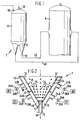
- Fig. 2 is a cross-section of the embodiment taken along line II-II of Fig. 1;
- Fig. 3 is an isometric view of the liner of the present invention;
- Fig. 4 is another alternate embodiment of the present invention; and
- Fig. 5 is still another alternate embodiment of the present invention.
- The drawings are of a process flow type in which auxiliary equipment, such as pumps, compressors, cleaning devices, etc. are not shown. All values are merely exemplary or calculated.
- Referring to Fig. 1, an apparatus for maintaining a uniform mass flow rate of a particulate solids and gas mixture discharged from a holding vessel apparatus, such as a
feed hopper 11 operated at elevated pressures of 1-200 bar, via aconduit 40 to a receiving reactor, such as agasifier 9, generally includes means for introducing the mixture, such as aninlet port 10, into thefeed hopper 11. The feed hopper 11 directs the material into generally cone-shaped receiving means shown generally at 7 and described more particularly with reference to Fig. 2. - Referring now to Fig. 2, the receiving
means 7 may be lined with a liner orinner shell 8 to be more particularly described with reference to Fig. 3. Theliner 8 has convergingwalls 12 forming an included angle of less than about 150 degrees, in particular less than about 90 degrees, and converging toward at least oneport 17 formed at the apex thereof for discharging the mixture therefrom. - The receiving
means 7 comprises ajacket 13 which surrounds theliner 8 and is mounted to form a substantially enclosed space, or manifold, between thewalls 12 of theliner 8 and thejacket 13. Thejacket 13 has at least one outlet port 15 at the lower end thereof which is in axial alignment with thedischarge port 17 of theliner 8 for discharging particles therefrom. - Means for isolating areas, advantageously first and
second areas porous plugs 14 ofwalls 12, such as apartition 22 within the substantially enclosed space between thejacket 13 and thewalls 12, forms at least two substantially enclosed compartments. Thejacket 13 includes means for selectively injecting gaseous fluid under pressure into first andsecond areas inlet ports fluid sources sources - The compartments formed within the substantially enclosed space between the
walls 12 and thejacket 13 permit gaseous fluids, possibly having different densities, such as nitrogen or other inert gas and synthesis gas which is mainly carbon monoxide, hydrogen, and water, to be selectively injected into the compartments. The gas injected fromsource 20 into thefirst area 18 may be more, equal, or less dense than the gas injected fromsource 21 intosecond area 19. Advantageously, the gas injected intoarea 18 would be inert and the gas injected intoarea 19 would be particulate-free synthesis gas. The gas injected intoarea 18 would flow upwards and could be vented to control the pressure in thefeed hopper 11 whereas the gas injected into thearea 19 flows downward and is transported to thegasifier 9. - Referring now to Fig. 3, the
liner 8 is advantageously made of a heavy, solid material such as stainless steel oralloy 20 and contains a plurality of holes such as 32 in thewalls 12. Theholes 32 are countersunk to receive and retain plugs shown generally at 14 of Figs. 2, 3A and 3B. Theplugs 14 are comprised ofinserts 16 made of porous material which may be metallic or non-metallic, such as sintered powdered metal, woven stainless steel, or porous ceramic, depending upon the operating conditions and type of coal used in the process. The arrow A in Figs. 3A and 3B represents gas flow.Inserts 16 are held in place by means of aretainer ring 27 which also allows for differential thermal expansion. The porous material ofinsert 16 has a selected permeability. The porous material of theinsert 16 facilitates the uniform distribution of gaseous fluid injected frompressurized sources liner 8 and prevents bridging of the particulate solids discharged from theliner 8 viadischarge port 17. - The pore size of the porous material and the type of porous material of the
insert 16 is based on, among other factors, the type of coal or fuel used and the temperature of operation. To allow greater operating flexibility to use various types of coal requiring differing pore sizes, theliner 8 is advantageously interchangeable with anotherliner having plugs 14 of a different permeability than thefirst liner 8. - Sufficient pressure drop over each plug should be maintained to ensure uniform flow over all the plugs.
- Furthermore, introduction of the gaseous fluid into the pores of the porous material of the
insert 16 imparts a pressure restriction to the gaseous fluid thus ensuring an even flow distribution of the fluid throughout theplugs 14 of thewalls 12 of theliner 8. Similarly, the porous material serves to control the bulk density of the mixture within theliner 8 and the discharge rate of the mixture leaving thehopper 11 viaport 17. - The configuration of the
insert 16 of Fig. 3A presents a smoother surface to the particulate solids whereas the configuration of Fig. 3B is simpler from a manufacturing standpoint. - The holes 32 (and plugs 14) are arranged to provide proper aeration for differing particulate matter and characteristics thereof. For example, the
holes 32 of theliner 8 may be arranged in three general zones of openness, 33, 34 and 35, where thezone 33 is 3% open, the zone 34 (bridging zone) is 10% open and thezone 35 is 5% open. Theentire liner 8 may have approximately 200holes 32, the diameter of each being on the order of 140 mm. The size of the plugs, configuration of the plugs and mechanical sealing depend also on the mechanical strength criteria, which are related to operating conditions. - The flow rate and direction of the gaseous fluid, advantageously nitrogen and synthesis gas, injected under pressure into the first and
second areas flow controllers plugs 14 ofwalls 12, but at a rate below that which would fluidize the particulate solids located above theplugs 14. It is undesirable to inject the gases at a rate sufficient to fluidize the particles above theinserts 16 as is typically done in conventional systems, because it results in more inert gas diluting the synthesis gas produced in thegasifier 9 and thus yielding a less valuable product. - The slip velocity above the
aeration cone 8, i.e. the relative superficial velocity between the gas and the coal within the hopper, should be less than 50% of the fluidization velocity and in particular near zero. Also, fluidization of the particles increases fluctuations of the mass flow rate of solids discharged from thecoal feed hopper 11. - Additionally, the flow rates of the gaseous fluid from
sources feed hopper 11. Terminal falling velocity is defined as the velocity at which the drag forces on a solid particle due to the flow of gases upward equals the downward force on the particle due to gravity. If the flow rates of the gases exceed the terminal falling velocity, then the solids will be discharged via thevent 50 rather than thedischarge port 17. - Advantageously, the flow rates of these gases from
sources - For example, for a uniform mass flow rate of particulate solids and gas mixture of 2000 kg/hr having a suspension density of 450 kg/m³ discharged from the
feed hopper 11, the rate of injecting nitrogen in the first area would be approximately 100 kg/hr. Should this rate be exceeded then the suspension density would be less than 450 kg/m³ and the synthesis gas produced in thegasifier 9 would be diluted by the nitrogen fromsource 20. Additionally, should this rate be somewhat less than the selected rate then the suspension density would be substantially higher than 450 kg/m³. Depending on the material and operating conditions, this situation could lead to less than stable flow. - Furthermore, the gaseous fluid may be injected in various directions and elevations to control the pressure and velocity profile which exists at the
discharge port 17. Depending on the physical properties of the particles being transported, it may be necessary to have more than two compartments or to inject gas above the compartmented region. - This selective injection provides for separate control of the mixture density within the
feed hopper 11 and the discharge density of the mixture leaving thehopper 11 via the outlet port 15. As a result, the discharge port 15 of thehopper 11 is much smaller than conventional technologies for suspension densities of 200-500 kg/m³ preferred in the present invention. - The diameter of the
discharge port 17 in the present invention is about 4 mm to about 150 mm for a solids and gas mixture having a suspension density of about 200-500 kg/m³. This diameter is larger than the maximum bridging diameter of the aerated particulate solids to prevent bridging of the solids as they exit thedischarge port 17. Conventional coal feed systems using gravity flow of solids assisted by aeration to break up bridging typically have a suspension density of less than 200 kg/m³ at the discharge outlet of the feed hopper and a corresponding feed vessel apparatus discharge port diameter of greater than about 150 mm. Diameters of thedischarge port 17 greater than about 150 mm for a given mass flow rate used in the present invention are not desirable because either the velocity or suspension density would fall below the desired limits thus resulting in fluctuations of the mass flow rate of the coal and gas mixture to thegasifier 9. - Additionally, the
smaller discharge port 17 diameter of the present invention, in conjunction with the compartmented injection of gaseous fluids, acts like a fluidic valve to control the particulate discharge rate and thereby eliminates the need for troublesome valves in transport hardware between the discharge of thehopper 11 and thegasifier 9. - Furthermore, the present invention may be provided with means for venting gas from the upper end of the
hopper 11, say viaport 50, for the purpose of maintaining an upward flow of gas through the solids in thefeed hopper 11 of approximately 2 mm/sec and thereby eliminate local bridging of the solids and provide smoother flow to thedischarge port 17. - Alternatively, the present invention may incorporate
liners 8A and 8B located inside thefeed hopper 11, rather than at the lower end of thehopper 11, as shown in Figs. 4 and 5, respectively. An advantage to the embodiment shown in Fig. 4 is that thetransport line 40 from thefeed hopper 11 to thegasifier 9 would be shorter for plant configurations in which the burners of the gasifier are elevated with respect to the feed hopper. Ashorter transport line 40 provides more uniform flow of the coal to the burners of thegasifier 9. - Another advantage of the alternate embodiments shown in Figs. 4 and 5, for the multiple
outlet feed hopper 11, is that the geometry of thehopper 11 is substantially simplified as a result of theliners 8A and 8B being located inside thehopper 11. - It would be recognized by one skilled in the art that references made with respect to the direction of flow of the gases and coal particles within the
liner 8 of the embodiment described in Fig. 1 would be reversed when referring to theliner 8A shown in Fig. 4 since theliner 8A is inverted with respect to the first containing means 8 shown in Fig. 2. - The foregoing description of the invention is merely intended to be explanatory thereof, and various changes in the details of the described method and apparatus may be within the scope of the appended claims without departing from the spirit of the invention.
Claims (2)
- An apparatus for maintaining a uniform mass flow rate of particulate solids and gas mixture discharged from a holding vessel apparatus (11) to a reactor (9), comprising:
means for introducing said mixture into a receiving means (7) having converging walls (12) which form at least one port (17) at the apex thereof for discharging said mixture therefrom;
the receiving means (7) comprising an inner at least partially porous shell (8) and a jacket (13) surrounding the inner shell (8), and mounted to form a substantially encloses space between the walls (12) of the inner shell (8) and said jacket (13), said jacket having at least one outlet port (15) at the converging end thereof in axial alignment with the discharge port (17) of said receiving means (7);
said jacket also being provided with a partition within the substantially enclosed space forming at least two substantially enclosed compartments;
means (20, 21) for selectively injecting gaseous fluid under pressure into said compartments; characterized by a plurality of plugs (14) being mounted in said walls (12), said plugs (14) being gaseous fluids and one face of said plugs being exposed to said particulate solids and gas mixture,
and means (25A, 25B, 26A, 26B) for independently controlling the flow rate and direction of said gaseous fluid under pressure at a rate sufficient to fluidize the particulate solids in proximity to said portion of porous plugs but at a rate below that which would fluidize the particulate solids located beyond the wide end of the converging walls (12),
said means comprising means for
injecting a first gaseous fluid having a selected density into a first compartment; and means for
injecting a second gaseous fluid having a density less than said first gaseous fluid into a second compartment. - The apparatus as claimed in claims 1 or 2, characterized in that said plugs (14) are arranged in zones (33, 34, 35) of different openness of said inner shell (8).
Applications Claiming Priority (2)
| Application Number | Priority Date | Filing Date | Title |
|---|---|---|---|
| US209602 | 1988-06-21 | ||
| US07/209,602 US5106240A (en) | 1988-06-21 | 1988-06-21 | Aerated discharge device |
Publications (2)
| Publication Number | Publication Date |
|---|---|
| EP0348007A1 EP0348007A1 (en) | 1989-12-27 |
| EP0348007B1 true EP0348007B1 (en) | 1992-08-26 |
Family
ID=22779452
Family Applications (1)
| Application Number | Title | Priority Date | Filing Date |
|---|---|---|---|
| EP89201645A Expired - Lifetime EP0348007B1 (en) | 1988-06-21 | 1989-06-21 | Aerated discharge device |
Country Status (8)
| Country | Link |
|---|---|
| US (1) | US5106240A (en) |
| EP (1) | EP0348007B1 (en) |
| JP (1) | JP2632216B2 (en) |
| CN (1) | CN1022926C (en) |
| AU (1) | AU616767B2 (en) |
| CA (1) | CA1330814C (en) |
| DE (1) | DE68902593T2 (en) |
| ZA (1) | ZA894640B (en) |
Families Citing this family (36)
| Publication number | Priority date | Publication date | Assignee | Title |
|---|---|---|---|---|
| DE4102965C2 (en) * | 1991-02-01 | 1999-09-09 | Krupp Koppers Gmbh | Device and method for conveying a fine-grained to dusty fuel in a gasification reactor under increased pressure |
| DE4105227A1 (en) * | 1991-02-20 | 1992-08-27 | Krupp Koppers Gmbh | METHOD AND DEVICE FOR THE GASIFICATION OF A FINE-GRAINED TO DUST-SHAPED FUEL WITH FLUE GAS RECYCLING |
| US5971399A (en) * | 1993-08-17 | 1999-10-26 | Chiyoda Corporation | Dual density sanitary pipe gasket |
| US5906482A (en) * | 1997-07-01 | 1999-05-25 | Extru-Tech, Inc. | Double wall vertical cooler |
| US6398462B1 (en) * | 1998-06-03 | 2002-06-04 | Nordson Corporation | Powder transfer apparatus having powder fluidizing tube |
| US6142067A (en) * | 1999-04-06 | 2000-11-07 | Roth; Eldon | Apparatus for treating ammoniated meats |
| US7044009B2 (en) * | 2002-05-20 | 2006-05-16 | Caterpillar Inc. | Dilution tunnel |
| US7093973B2 (en) * | 2002-10-11 | 2006-08-22 | Freezing Machines, Inc. | Sparging device and method for adding a processing fluid to a foodstuff |
| US20090218371A1 (en) * | 2003-03-25 | 2009-09-03 | Wouter Detlof Berggren | Sluice Vessel and Method of Operating Such a Sluice Vessel |
| DE10356480B4 (en) * | 2003-12-03 | 2005-10-27 | Loesche Gmbh | Process and apparatus for pneumatic conveying of solids |
| DE502007003920D1 (en) * | 2006-12-14 | 2010-07-08 | Sulzer Chemtech Ag | Porous dosing element with coating |
| US20080260920A1 (en) * | 2007-04-23 | 2008-10-23 | Eldon Roth | Method for packaging and storing fresh meat products |
| DE102008008419A1 (en) * | 2008-02-09 | 2009-09-10 | Uhde Gmbh | Method and device for receiving and transferring fine to coarse-grained solids from a container into a system of higher pressure |
| DE102008012731A1 (en) | 2008-03-05 | 2009-09-24 | Uhde Gmbh | Device for discharging fine-grained or dust-like solids from a container |
| DE102008014475A1 (en) * | 2008-03-17 | 2009-11-12 | Uhde Gmbh | Method and device for the metered removal of a fine to coarse-grained solid or solid mixture from a storage container |
| ITBG20080028A1 (en) * | 2008-05-05 | 2009-11-06 | Larix Srl | ACTIVATION AND FLUIDIFICATION SYSTEM FOR SILOS OR GRANULAR MATERIALS CONTAINERS. |
| DE102008024576B3 (en) * | 2008-05-21 | 2009-10-01 | Uhde Gmbh | Device for discharging a solid from a container |
| US8951315B2 (en) * | 2008-11-12 | 2015-02-10 | Exxonmobil Research And Engineering Company | Method of injecting fuel into a gasifier via pressurization |
| WO2010080529A1 (en) * | 2008-12-17 | 2010-07-15 | Johan Gunther | Modified storage pod and feeding system for binder utilized for in-situ pilings |
| US20110048317A1 (en) * | 2009-08-31 | 2011-03-03 | Heat And Control, Inc. | Portable, compact, food seasoning replenishment system |
| CN101875862B (en) * | 2009-10-27 | 2013-02-13 | 武汉凯迪工程技术研究总院有限公司 | Method and device for conveying charcoal powder to gasification furnace in biomass gasification system |
| US8534904B2 (en) * | 2010-03-10 | 2013-09-17 | Lord Ltd., Lp | Apparatus for restarting a gas-solids contactor |
| DE102010018108A1 (en) * | 2010-04-24 | 2011-10-27 | Uhde Gmbh | Apparatus for supplying a plurality of burners with fine-grained fuel |
| DE102010018841A1 (en) | 2010-04-29 | 2011-11-03 | Uhde Gmbh | discharge cone |
| CN102417111A (en) * | 2010-09-28 | 2012-04-18 | 通用电气公司 | Conveying system and method |
| FR2977807B1 (en) * | 2011-07-13 | 2015-04-03 | Verdesis France | DEVICE FOR ADSORPTING COMPOUNDS FROM A GAS SUPPLY |
| CN102826240B (en) * | 2012-08-30 | 2014-06-25 | 肖龙 | Tons of bagging equipment |
| US9044047B2 (en) | 2012-11-16 | 2015-06-02 | Heat And Control, Inc. | Food seasoning replenishment system and apparatus |
| WO2014201556A1 (en) | 2013-06-17 | 2014-12-24 | Hatch Ltd. | Feed flow conditioner for particulate feed materials |
| CN205114514U (en) * | 2015-10-26 | 2016-03-30 | 天津鑫利恒科技有限公司 | Pneumatic feeding device |
| JP6695163B2 (en) * | 2016-02-17 | 2020-05-20 | 三菱日立パワーシステムズ株式会社 | Fine powder fuel supply device and method, integrated gasification combined cycle facility |
| CN107284883B (en) * | 2017-07-19 | 2024-01-23 | 陕西延长石油(集团)有限责任公司 | Intermittent lock hopper pressurized pulverized coal conveying device and conveying method |
| US20210001289A1 (en) * | 2018-03-08 | 2021-01-07 | Hitachi Metals, Ltd. | Slurry storing and mixing device |
| WO2020154768A1 (en) * | 2019-01-30 | 2020-08-06 | Pelleton Global Renewables Ltd. | Desiccation hopper |
| GB201906555D0 (en) * | 2019-05-09 | 2019-06-26 | William Curle Developments Ltd | Improvements in or relating to storage and conveying apparatuses |
| US11325776B1 (en) * | 2021-05-26 | 2022-05-10 | The Young Industries, Inc. | Mass-flow hopper |
Family Cites Families (48)
| Publication number | Priority date | Publication date | Assignee | Title |
|---|---|---|---|---|
| US3159432A (en) * | 1964-12-01 | Flow control of pulverant material | ||
| CA681824A (en) * | 1964-03-10 | R. Hawkinson Donald | Feeding powder at uniform rates | |
| US699405A (en) * | 1901-12-10 | 1902-05-06 | Ray C Newhouse | Sand-blast. |
| US2115023A (en) * | 1935-03-18 | 1938-04-26 | Reconstruction Finance Corp | Means for transporting material |
| US2170258A (en) * | 1936-08-27 | 1939-08-22 | Smidth & Co As F L | Method and apparatus for handling powdered material |
| DE714067C (en) * | 1938-06-08 | 1941-11-20 | Hannoversche Maschb Act Ges Vo | Storage container discharge funnel for dust-like material with an adjoining discharge line |
| CH207033A (en) * | 1938-12-07 | 1939-09-15 | Polysius G Ag | Method and device for loosening dusty goods in containers. |
| US2400194A (en) * | 1943-09-30 | 1946-05-14 | Universal Oil Prod Co | Method for contacting fluids with finely divided solid particles |
| US2568379A (en) * | 1945-11-26 | 1951-09-18 | Union Oil Co | Level control |
| US2631759A (en) * | 1947-11-08 | 1953-03-17 | Sinclair Refining Co | Slide valve for controlling the flow of suspended solids |
| US2499766A (en) * | 1948-11-30 | 1950-03-07 | Lester R Macleod | Dust conveying |
| US2708602A (en) * | 1951-12-18 | 1955-05-17 | Smidth & Co As F L | Discharge apparatus for pulverulent or granular material |
| US2715551A (en) * | 1952-12-09 | 1955-08-16 | Air Reduction | Apparatus for dispensing powdered materials at superatmospheric pressure |
| US2806781A (en) * | 1955-01-20 | 1957-09-17 | Air Reduction | Method and apparatus for conveying finely-divided material |
| US2794686A (en) * | 1955-10-31 | 1957-06-04 | Whirl Air Flow Corp | Air flow conveying system |
| FR1230526A (en) * | 1959-03-21 | 1960-09-16 | Siderurgie Fse Inst Rech | Automatic regulation device of a pressurized powder dispenser |
| US3007744A (en) * | 1959-10-22 | 1961-11-07 | Gordon Company Inc | Powder delivery apparatus and method |
| DE1141588B (en) * | 1960-05-16 | 1962-12-20 | Polysius Gmbh | Permeable plate with fine parallel channels, especially for blowing compressed air into pneumatically conveyed material |
| US3121593A (en) * | 1961-02-23 | 1964-02-18 | Simpson Herbert Corp | Pneumatic material handling apparatus |
| GB999106A (en) * | 1961-04-12 | 1965-07-21 | Buehler Ag Geb | Improvements in discharging means for silo bins |
| US3230016A (en) * | 1962-06-01 | 1966-01-18 | Petrocarb Inc | Process and apparatus for pneumatic conveyance of solids |
| US3289396A (en) * | 1963-01-14 | 1966-12-06 | Butler Manufacturing Co | Pressure equalizing and filter arrangement for pressurized storage tanks having voids therein |
| US3285739A (en) * | 1964-01-06 | 1966-11-15 | Petrocarb Inc | Process for producing nodular cast iron |
| US3237812A (en) * | 1964-04-30 | 1966-03-01 | Acf Ind Inc | Apparatus for handling bulk materials |
| US3379345A (en) * | 1965-12-21 | 1968-04-23 | Werner & Pfleiderer | Storage vessel or feed unit for powdered materials with air-permeable guiding or separating walls |
| DE1934074U (en) * | 1965-12-21 | 1966-03-03 | Werner & Pfleiderer | ACCUMULATOR OR CONVEYOR ELEMENT WITH AIR PERMEABLE CONDUCTOR OR PARTITION WALLS FOR POWDERED SUBSTANCES. |
| FR1474822A (en) * | 1966-01-08 | 1967-03-31 | Improvements to pneumatic spraying machines | |
| US3301604A (en) * | 1966-03-14 | 1967-01-31 | Viking Corp | Particulate material conveying system |
| US3367724A (en) * | 1966-05-06 | 1968-02-06 | Halliburton Co | Aerating cartridge |
| US3479093A (en) * | 1967-04-27 | 1969-11-18 | Blackstone Corp | Inoculation feeders |
| US3424352A (en) * | 1967-06-08 | 1969-01-28 | Union Tank Car Co | Apparatus for discharge and cleanout of pulverulent material from tank cars |
| US3693839A (en) * | 1971-03-05 | 1972-09-26 | Pullman Inc | Pneumatic discharge arrangement for railway car hoppers |
| US3720351A (en) * | 1971-05-06 | 1973-03-13 | Babcock & Wilcox Co | Pulverized fuel delivery system for a blast furnace |
| US3822919A (en) * | 1971-07-09 | 1974-07-09 | Kaiser Ind Corp | Apparatus and method for fluidizing and handling particulates |
| US4067623A (en) * | 1974-04-02 | 1978-01-10 | Polysius Ag | Pneumatic pressure conveyor for fine material |
| DE2455127C2 (en) * | 1974-11-21 | 1986-02-27 | Shell Internationale Research Maatschappij B.V., Den Haag | Process for discharging residues from a gasification chamber under increased pressure |
| DE2554565A1 (en) * | 1975-12-04 | 1977-06-16 | Otto & Co Gmbh Dr C | PLANT FOR THE PRESSURE GASIFICATION OF FINE-GRAIN FUELS |
| US4018588A (en) * | 1976-05-10 | 1977-04-19 | Ecolaire Incorporated | Method and apparatus for handling slag handling |
| DE2746086C3 (en) * | 1977-10-13 | 1980-04-17 | Guenter O. 7421 Mehrstetten Stumpf | Device for cutting layers of fabric packages or the like |
| DE2829629C2 (en) * | 1978-07-06 | 1982-07-29 | Ruhrchemie Ag, 4200 Oberhausen | Method and device for discharging residues from the pressure system of a pressure gasification plant |
| JPS5598030A (en) * | 1979-01-16 | 1980-07-25 | Nippon Alum Mfg Co Ltd:The | Method and device for continuously supplying powder |
| JPS57102431A (en) * | 1980-12-12 | 1982-06-25 | Denka Consult & Eng Co Ltd | Under-pressure distributing and transporting apparatus for highly pressurized powdered granules |
| JPS57107316A (en) * | 1980-12-22 | 1982-07-03 | Denka Consult & Eng Co Ltd | Method and device of distribution control for high pressure powder |
| US4381898A (en) * | 1981-01-21 | 1983-05-03 | Eutectic Corporation | Device for the controlled feeding of powder material |
| JPS58104833A (en) * | 1981-12-12 | 1983-06-22 | Kawasaki Steel Corp | Continuously supplying method and device for transporting granule from one distributive transportation tank to plural supply ends by controlling mass flow to optional preset value |
| JPS59124624A (en) * | 1982-12-27 | 1984-07-18 | Kawasaki Steel Corp | Method for distribution and transport of pulverized/ granular material |
| US4693189A (en) * | 1986-11-03 | 1987-09-15 | Powers Richard M | Fluidized bed feeder |
| AU620408B2 (en) * | 1988-06-21 | 1992-02-20 | Shell Internationale Research Maatschappij B.V. | Aeration tube discharge control device |
-
1988
- 1988-06-21 US US07/209,602 patent/US5106240A/en not_active Expired - Lifetime
-
1989
- 1989-06-19 ZA ZA894640A patent/ZA894640B/en unknown
- 1989-06-19 JP JP1154773A patent/JP2632216B2/en not_active Expired - Fee Related
- 1989-06-19 AU AU36571/89A patent/AU616767B2/en not_active Expired
- 1989-06-19 CN CN89106282A patent/CN1022926C/en not_active Expired - Lifetime
- 1989-06-20 CA CA000603353A patent/CA1330814C/en not_active Expired - Lifetime
- 1989-06-21 EP EP89201645A patent/EP0348007B1/en not_active Expired - Lifetime
- 1989-06-21 DE DE8989201645T patent/DE68902593T2/en not_active Expired - Lifetime
Also Published As
| Publication number | Publication date |
|---|---|
| CN1040048A (en) | 1990-02-28 |
| EP0348007A1 (en) | 1989-12-27 |
| JPH0245594A (en) | 1990-02-15 |
| US5106240A (en) | 1992-04-21 |
| DE68902593T2 (en) | 1993-01-21 |
| DE68902593D1 (en) | 1992-10-01 |
| AU616767B2 (en) | 1991-11-07 |
| CN1022926C (en) | 1993-12-01 |
| CA1330814C (en) | 1994-07-19 |
| JP2632216B2 (en) | 1997-07-23 |
| ZA894640B (en) | 1990-02-28 |
| AU3657189A (en) | 1990-01-04 |
Similar Documents
| Publication | Publication Date | Title |
|---|---|---|
| EP0348007B1 (en) | Aerated discharge device | |
| US4941779A (en) | Compartmented gas injection device | |
| US5129766A (en) | Aeration tube discharge control device | |
| EP0348008B1 (en) | Aeration tube discharge control device | |
| US3981690A (en) | Agglomerating combustor-gasifier method and apparatus for coal gasification | |
| US4531949A (en) | Entrained flow coal gasification process | |
| JPS58184405A (en) | Solid grain fuel fluidized-bed treating furnace and its method | |
| EP0308024B1 (en) | Compartmented gas injection device | |
| US4830545A (en) | Feed line design | |
| EP0308027B1 (en) | Control of suspension density using radiation source | |
| EP0308026B1 (en) | Feed vessel apparatus for coal gasification | |
| WO1990011824A1 (en) | Fluidized bed reactor with protected fluid distributor | |
| US4934876A (en) | Aeration apparatus for discharge control of particulate matter | |
| US4943190A (en) | Aeration tube discharge control device with variable fluidic valve | |
| CA1307651C (en) | Feed hopper design | |
| US4834588A (en) | Feed line-pulsed gas injection | |
| EP0109109B1 (en) | Process for the partial combustion of solid fuel with fly ash recycle | |
| CN1022925C (en) | Aeration tube discharge control device | |
| EP1058051B1 (en) | Fluidized bed gasification furnace | |
| US4844663A (en) | Feed line-ultrasonic activated gas injection | |
| CN103384636B (en) | Plug resistant nozzle for fluidization of particulates |
Legal Events
| Date | Code | Title | Description |
|---|---|---|---|
| PUAI | Public reference made under article 153(3) epc to a published international application that has entered the european phase |
Free format text: ORIGINAL CODE: 0009012 |
|
| AK | Designated contracting states |
Kind code of ref document: A1 Designated state(s): DE GB IT NL SE |
|
| 17P | Request for examination filed |
Effective date: 19900425 |
|
| 17Q | First examination report despatched |
Effective date: 19910823 |
|
| GRAA | (expected) grant |
Free format text: ORIGINAL CODE: 0009210 |
|
| AK | Designated contracting states |
Kind code of ref document: B1 Designated state(s): DE GB IT NL SE |
|
| ITF | It: translation for a ep patent filed | ||
| REF | Corresponds to: |
Ref document number: 68902593 Country of ref document: DE Date of ref document: 19921001 |
|
| PLBI | Opposition filed |
Free format text: ORIGINAL CODE: 0009260 |
|
| 26 | Opposition filed |
Opponent name: KRUPP KOPPERS GMBH Effective date: 19930511 |
|
| NLR1 | Nl: opposition has been filed with the epo |
Opponent name: KRUPP KOPPERS GMBH |
|
| PLBN | Opposition rejected |
Free format text: ORIGINAL CODE: 0009273 |
|
| STAA | Information on the status of an ep patent application or granted ep patent |
Free format text: STATUS: OPPOSITION REJECTED |
|
| 27O | Opposition rejected |
Effective date: 19940613 |
|
| NLR2 | Nl: decision of opposition | ||
| EAL | Se: european patent in force in sweden |
Ref document number: 89201645.2 |
|
| PGFP | Annual fee paid to national office [announced via postgrant information from national office to epo] |
Ref country code: SE Payment date: 19970512 Year of fee payment: 9 |
|
| PG25 | Lapsed in a contracting state [announced via postgrant information from national office to epo] |
Ref country code: SE Free format text: LAPSE BECAUSE OF NON-PAYMENT OF DUE FEES Effective date: 19980622 |
|
| EUG | Se: european patent has lapsed |
Ref document number: 89201645.2 |
|
| REG | Reference to a national code |
Ref country code: GB Ref legal event code: IF02 |
|
| PGFP | Annual fee paid to national office [announced via postgrant information from national office to epo] |
Ref country code: IT Payment date: 20080624 Year of fee payment: 20 |
|
| PGFP | Annual fee paid to national office [announced via postgrant information from national office to epo] |
Ref country code: DE Payment date: 20080630 Year of fee payment: 20 Ref country code: NL Payment date: 20080630 Year of fee payment: 20 |
|
| PGFP | Annual fee paid to national office [announced via postgrant information from national office to epo] |
Ref country code: GB Payment date: 20080529 Year of fee payment: 20 |
|
| REG | Reference to a national code |
Ref country code: GB Ref legal event code: PE20 Expiry date: 20090620 |
|
| PG25 | Lapsed in a contracting state [announced via postgrant information from national office to epo] |
Ref country code: NL Free format text: LAPSE BECAUSE OF EXPIRATION OF PROTECTION Effective date: 20090621 |
|
| NLV7 | Nl: ceased due to reaching the maximum lifetime of a patent |
Effective date: 20090621 |
|
| PG25 | Lapsed in a contracting state [announced via postgrant information from national office to epo] |
Ref country code: GB Free format text: LAPSE BECAUSE OF EXPIRATION OF PROTECTION Effective date: 20090620 |