EP0347860A2 - Diagnostikverfahren zum Prüfen des Normalzustandes von Datenübertragung zwischen seriell verbundenen Steuereinheiten - Google Patents
Diagnostikverfahren zum Prüfen des Normalzustandes von Datenübertragung zwischen seriell verbundenen Steuereinheiten Download PDFInfo
- Publication number
- EP0347860A2 EP0347860A2 EP89111240A EP89111240A EP0347860A2 EP 0347860 A2 EP0347860 A2 EP 0347860A2 EP 89111240 A EP89111240 A EP 89111240A EP 89111240 A EP89111240 A EP 89111240A EP 0347860 A2 EP0347860 A2 EP 0347860A2
- Authority
- EP
- European Patent Office
- Prior art keywords
- sub
- controller
- main controller
- controllers
- diagnostic
- Prior art date
- Legal status (The legal status is an assumption and is not a legal conclusion. Google has not performed a legal analysis and makes no representation as to the accuracy of the status listed.)
- Withdrawn
Links
Images


Classifications
-
- G—PHYSICS
- G05—CONTROLLING; REGULATING
- G05B—CONTROL OR REGULATING SYSTEMS IN GENERAL; FUNCTIONAL ELEMENTS OF SUCH SYSTEMS; MONITORING OR TESTING ARRANGEMENTS FOR SUCH SYSTEMS OR ELEMENTS
- G05B19/00—Program-control systems
- G05B19/02—Program-control systems electric
- G05B19/418—Total factory control, i.e. centrally controlling a plurality of machines, e.g. direct or distributed numerical control [DNC], flexible manufacturing systems [FMS], integrated manufacturing systems [IMS] or computer integrated manufacturing [CIM]
- G05B19/4181—Total factory control, i.e. centrally controlling a plurality of machines, e.g. direct or distributed numerical control [DNC], flexible manufacturing systems [FMS], integrated manufacturing systems [IMS] or computer integrated manufacturing [CIM] characterised by direct numerical control [DNC]
-
- G—PHYSICS
- G05—CONTROLLING; REGULATING
- G05B—CONTROL OR REGULATING SYSTEMS IN GENERAL; FUNCTIONAL ELEMENTS OF SUCH SYSTEMS; MONITORING OR TESTING ARRANGEMENTS FOR SUCH SYSTEMS OR ELEMENTS
- G05B19/00—Program-control systems
- G05B19/02—Program-control systems electric
- G05B19/18—Numerical control [NC], i.e. automatically operating machines, in particular machine tools, e.g. in a manufacturing environment, so as to execute positioning, movement or co-ordinated operations by means of program data in numerical form
- G05B19/406—Numerical control [NC], i.e. automatically operating machines, in particular machine tools, e.g. in a manufacturing environment, so as to execute positioning, movement or co-ordinated operations by means of program data in numerical form characterised by monitoring or safety
- G05B19/4063—Monitoring general control system
-
- Y—GENERAL TAGGING OF NEW TECHNOLOGICAL DEVELOPMENTS; GENERAL TAGGING OF CROSS-SECTIONAL TECHNOLOGIES SPANNING OVER SEVERAL SECTIONS OF THE IPC; TECHNICAL SUBJECTS COVERED BY FORMER USPC CROSS-REFERENCE ART COLLECTIONS [XRACs] AND DIGESTS
- Y02—TECHNOLOGIES OR APPLICATIONS FOR MITIGATION OR ADAPTATION AGAINST CLIMATE CHANGE
- Y02P—CLIMATE CHANGE MITIGATION TECHNOLOGIES IN THE PRODUCTION OR PROCESSING OF GOODS
- Y02P90/00—Enabling technologies with a potential contribution to greenhouse gas [GHG] emissions mitigation
- Y02P90/02—Total factory control, e.g. smart factories, flexible manufacturing systems [FMS] or integrated manufacturing systems [IMS]
Definitions
- the present invention relates generally to a robotized system and more specifically to a diagnostic technique which is utilized to establish which unit or units are not correctly receiving data transmissions in a loop network of robot operating sub-controllers.
- JP-A-62-110,581 discloses an assembly system which is used in connection with the assembly of an automotive vehicle.
- This system is arranged to permit small numbers of each of large number of different types of vehicle to be assembled without the need to revise the construction and arrangement of the line and to obviate the need to make a prolonged run of the same type of vehicle which vehicles must be subsequently stored pending the receipt of orders for the same.
- the system includes a stage in which the body side, under body and roof panels are placed in position on a vehicle chassis by program controlled locater units which are capable of three dimensional position adjustment.
- this assembly stage the requisite data needed to induce each of the locaters to move in the desired manner in the desired place and the desired time, is transmitted to each of the devices in response to a vehicle type signal which is indicative of the type of vehicle which is to be assembled in the stage.
- This data includes the positioning of the various elements and panels which are to be disposed on the basic chassis and clamped in place.
- a main controller 6 is arranged to transmit data relating to the amount of movement and direction in the movement each locator should undergo, to a plurality of sub-controllers 11a to 11d.
- the main controller 6 is arranged to transmit both instruction and timing signals by way of cables 12. These cables 12, in order to reduce the size and bulk of the same are usually coaxial, glass fiber (light transmitting) or the like type. In this arrangement the main controller 6 is connected with each of the sub controllers by way of an independent cable.
- the above object is achieved by an arrangement which features the provision of an indicator such as a LED or the like, on each of the sub-controllers which control one or more robots and/or locators; and the use of a test signal which is sequentially applied to each of the sub-controller units. If the test signal is properly received, the indicator on the respective sub-controller is suitably conditioned to indicated the reception status of the instant unit and the test is then applied to the next sub-controller in the loop.
- an indicator such as a LED or the like
- a first aspect of the present invention is deemed to comprise a diagnostic system for testing data transmission normality which features: a sub-controller which is connected serially in a loop circuit with a main controller, the main controller issuing control signals and a test signal, the sub-controller including: means for receiving the signals originally issued by the main controller; diagnostic means for determining, in response to the test signal, if signals are being properly received by the sub-controller; and an indicator, the indicator being operatively connected with the diagnostic means and arranged to be actuated by the diagnostic means in the event that proper signal receipt is indicated.
- a second aspect of the present invention is deemed to comprise a diagnostic system for testing data transmission normality between a plurality of sub-controllers which are connected serially in a loop circuit with a main controller, which features: means disposed in the main controller for issuing control signals and a test signal; means disposed in each of the sub-controllers for receiving the signals originally issued by the main controller; diagnostic means for determining, in response to the test signal, if the signals originally issued by the main controller are being properly received by the sub-controller; and an indicator, the indicator being operatively connected with the diagnostic means and arranged to be actuated by the diagnostic means in the event that proper signal receipt is indicated.
- a third aspect of the present invention is deemed to comprise a diagnostic system for testing data transmission normality which features: a main controller, the main controller being arranged to issue first and second signals; a plurality of sub-controllers, the sub-controllers being connected serially to define a loop which includes the main controller, each of the sub-controllers including: means for receiving the first and second signals; diagnostic means for comparing the first and second signals and determining if the signals are being properly received by the sub-controller; and indicator means operatively connccted with the diagnostic means for producing an indication of the signal receiving status of the sub-controller.
- a fourth aspect of the present invention is deemed to comprise a diagnostic system for testing data transmission normality between a plurality of sub-controllers which are connected serially in a loop circuit with a main controller, which comprises: diagnostic means in each of the sub-controllers for comparing the content of a signal issued by the main controller with a predetermined content to determine if the signal is being properly received by the sub-controller; and an indicator, the indicator being operatively connected with the diagnostic means and arranged to be actuated by the diagnostic means in a manner to indicate the signal receiving status of the sub-controller.
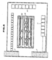
- Figs. 5 to 8 show a vehicle assembly stage of the nature in which the present invention finds advantageous application.
- this assembly stage is such that a floor main panel, left and right body side panels, roof panel and rear panel are placed in position on a chassis, clamped and permanently connected via spot welding.
- the main floor panel is formed by pressing and the like processing. Following its formation, this main floor panel is, as shown in Fig. 7, transported along a transfer bar 1 and introduced into the illustrated stage.
- the stage in this instance comprises a frame 3 which is supported on the factory floor or suitable base 2.
- Posts 4 support a mezzanine floor 5 above the frame 3 which floor 5 serves to support the main controller 6.
- the mezzanine floor is provided with a hand rail 5a for safety.
- a ladder 7 is provided at one end of the stage to permit personal to climb for the purposes of inspecting the main controller 6 and the like.
- the frame 3 includes laterally extending structural members 3a upon which a plurality of first positioning locaters 8 are operatively mounted. These locators 8 are arranged to support and adjust the position of body B and are provided with fingers and forks elements which can be adjusted in a manner which permits the adjustment to support different size and types of chassis.
- the first of these two documents discloses a work piece support device which features two pincer member which can be moved toward and away from each other and which can be varied in length in a manner to accommodate different shaped work pieces.
- the device is mounted on a manipulator which selectively displaces the same in three mutually opposed directions.
- This document further discloses location and locking probes can used in combination with the support device to locate and/or lock the work piece in place.
- the second of the two documents discloses a manipulator which features the use of a single motor and a plurality of flexible cables which are interconnected with the motor via a plurality of clutches which can be selectively engaged.
- the cables transmit rotational energy so the element of the manipulator via rotation/liner motion translation devices.
- work robots 9 ar transported along fixed guides 10 to assume predetermined positions with respect to the frame 3 and the body B which is supported therein.
- the work robots 9 are not only located to the sides of the frame but also above the same as shown in Figs. 5 and 7 for example.
- each of the sub-controllers 11a - 11d which are shown in Fig. 1 are connected by communication cables 12 in a manner to define a ring network N.
- Each of the sub-controllers are arranged in the manner depicted in Fig. 2. That is to say, each of the sub-controllers include, a signal control section 13; a received signal data and format discrimination section 14; a data deciphering section 15; a test result evaluation section 16; and I/O board 17 and a LED or the like type of indicator device 18 which can be activated in a manner to indicate a malfunction; all of which are operatively connected in the schematically illustrated manner.
- Fig. 3(a) shows the data pattern or arrangement of the command signals which are issued by the main controller 6.
- a main data section is arranged between a initialization or synchronization pattern and a final or termination pattern.
- content of the main data contains the locator movement and timing control information for each of the sub-controllers in turn, under normal control modes.
- this main data section contains the information necessary for executing the diagnostic control.
- Fig. 3(b) shows the response data pattern which is contained in the signal fed back to the main controller 6 from the last of the serially connected sub-controllers 11d. As shown, located between the synchronization patter and the termination pattern is the sequentially compounded response data for each of the sub-controllers 11a - 11d.
- Fig. 4 depicts in flow chart form, the steps which are executed by the diagnostic technique according to the present invention in each of the sub-controllers.
- the command data which is contained in the signal issued by the main controller 6, is received by the signal control section 13 of the first sub-controller 11a.
- This data is transferred to the data discrimination section 13 determines if a predetermined format can be matched nor not (step 1002). In the case of a format mismatch, an error data is included in the signal which is supplied to the next sub-controller (step 1003).
- the data is transferred to the data deciphering section 15 wherein it is determined if the transferred data is compatible with the instant sub-controller (step 1004).
- the results of the deciphering are transferred to the test result evaluation section 16 wherein it is determined if the results of the deciphering are contained in the communication test information or not (step 1005).
- the results are not found, then at step 1007 normal control routines are run. However, if requisite information is found then, at step 1006, an illumination signal is outputted via an I/O board to an LED to indicate that data is being suitably received by the instant sub-controller.
- the LED on sub-controller 11c will be illuminated while that on 11d will remain unenergized. Accordingly, the operator in attendance will be able to ascertain from the illumination/non-illumination of the LED which unit or units are not properly receiving data and can therefore quickly locate the trouble spot in the cables 12.
- this feature enables the rapid location and repair of any cable and data related transmission problems and therefore permits the amount of downtime which tends to result from such a malfunction to be reduced drastically. The resulting improvement in production efficiency which can be achieved will be readily appreciated.
- the present invention is not limited to the above described technique.
- special data eg. a particular code
- the various other modification possible are deemed to be within the perview of the skilled worker when provided with the guidance of the instant specification.
Landscapes
- Engineering & Computer Science (AREA)
- Manufacturing & Machinery (AREA)
- Physics & Mathematics (AREA)
- General Physics & Mathematics (AREA)
- Automation & Control Theory (AREA)
- Human Computer Interaction (AREA)
- General Engineering & Computer Science (AREA)
- Quality & Reliability (AREA)
- Testing And Monitoring For Control Systems (AREA)
- Selective Calling Equipment (AREA)
- Small-Scale Networks (AREA)
Applications Claiming Priority (2)
| Application Number | Priority Date | Filing Date | Title |
|---|---|---|---|
| JP150059/88 | 1988-06-20 | ||
| JP63150059A JPH024052A (ja) | 1988-06-20 | 1988-06-20 | 通信異常チェック方法 |
Publications (2)
| Publication Number | Publication Date |
|---|---|
| EP0347860A2 true EP0347860A2 (de) | 1989-12-27 |
| EP0347860A3 EP0347860A3 (de) | 1992-07-22 |
Family
ID=15488612
Family Applications (1)
| Application Number | Title | Priority Date | Filing Date |
|---|---|---|---|
| EP19890111240 Withdrawn EP0347860A3 (de) | 1988-06-20 | 1989-06-20 | Diagnostikverfahren zum Prüfen des Normalzustandes von Datenübertragung zwischen seriell verbundenen Steuereinheiten |
Country Status (2)
| Country | Link |
|---|---|
| EP (1) | EP0347860A3 (de) |
| JP (1) | JPH024052A (de) |
Cited By (2)
| Publication number | Priority date | Publication date | Assignee | Title |
|---|---|---|---|---|
| EP0793084A3 (de) * | 1996-02-28 | 1998-04-01 | Toyota Jidosha Kabushiki Kaisha | Eine Kommunikationskontroll-Vorrichtung zur Kommunikationskontrolle zwischen einer Gruppe von elektronischen Einheiten in Kfz |
| EP1747839A1 (de) * | 2005-07-29 | 2007-01-31 | Fanuc Ltd | Laserbearbeitung Robotersystem |
Families Citing this family (2)
| Publication number | Priority date | Publication date | Assignee | Title |
|---|---|---|---|---|
| JPH0457600U (de) * | 1990-09-20 | 1992-05-18 | ||
| US6238042B1 (en) * | 1994-09-16 | 2001-05-29 | Seiko Epson Corporation | Ink cartridge for ink jet printer and method of charging ink into said cartridge |
Family Cites Families (4)
| Publication number | Priority date | Publication date | Assignee | Title |
|---|---|---|---|---|
| US4251858A (en) * | 1979-03-06 | 1981-02-17 | The Boeing Company | Paging, status monitoring and report compiling system for support, maintenance and management of operator-supervised automatic industrial machines |
| US4393796A (en) * | 1982-06-28 | 1983-07-19 | The Singer Company | Arrangement for operating an electronically controlled sewing machine in a diagnostic mode |
| DE3440025A1 (de) * | 1984-11-02 | 1986-05-07 | Pulsotronic Merten Gmbh & Co Kg, 5270 Gummersbach | Speicherprogrammierbare steuerung mit einer ueberwachungseinrichtung der melde- und/oder stellglieder |
| EP0208998A3 (de) * | 1985-07-19 | 1989-01-04 | Rodger T. Lovrenich | Dezentralisiertes Steuerungssystem und Verbindung dazu |
-
1988
- 1988-06-20 JP JP63150059A patent/JPH024052A/ja active Pending
-
1989
- 1989-06-20 EP EP19890111240 patent/EP0347860A3/de not_active Withdrawn
Cited By (3)
| Publication number | Priority date | Publication date | Assignee | Title |
|---|---|---|---|---|
| EP0793084A3 (de) * | 1996-02-28 | 1998-04-01 | Toyota Jidosha Kabushiki Kaisha | Eine Kommunikationskontroll-Vorrichtung zur Kommunikationskontrolle zwischen einer Gruppe von elektronischen Einheiten in Kfz |
| EP1747839A1 (de) * | 2005-07-29 | 2007-01-31 | Fanuc Ltd | Laserbearbeitung Robotersystem |
| US7291806B2 (en) | 2005-07-29 | 2007-11-06 | Fanuc Ltd. | Robot laser processing system |
Also Published As
| Publication number | Publication date |
|---|---|
| EP0347860A3 (de) | 1992-07-22 |
| JPH024052A (ja) | 1990-01-09 |
Similar Documents
| Publication | Publication Date | Title |
|---|---|---|
| EP0346839B1 (de) | Lernverfahren und -system für Roboter | |
| US5910894A (en) | Sensor based assembly tooling improvements | |
| US4831316A (en) | Control system for an industrial robot with a foresight function | |
| US6748476B2 (en) | Control system including controller and field devices | |
| US20020054795A1 (en) | Numeric controlled drilling jig-multiple-axis aerospace drilling machine | |
| EP0423332B1 (de) | Fernsteuerung für fahrzeuge | |
| US11846924B2 (en) | Procedure for configuring a modular safety switching device | |
| EP0114505A1 (de) | Einrichtung und Verfahren zum Kalibrieren eines Roboters | |
| EP2763888B1 (de) | Direkter fahrzeugkarosserieverriegelungssensor und verfahren | |
| US20100161123A1 (en) | Automatic machine system | |
| US5077674A (en) | Performance feedback system | |
| EP0347860A2 (de) | Diagnostikverfahren zum Prüfen des Normalzustandes von Datenübertragung zwischen seriell verbundenen Steuereinheiten | |
| US10081105B2 (en) | Method for verifying the assignment of a drive to a control device | |
| WO1994016401A1 (en) | Sensory based assembly tooling improvements | |
| CN109592067B (zh) | 使航空航天载具的机身结构移动为组装对准的对准系统和方法 | |
| CN116540598B (zh) | 一种飞机复杂部件双机器人智能钻铆集成管理与控制系统 | |
| US20220410389A1 (en) | Robot system and erroneous wiring detection method thereof | |
| US7043333B2 (en) | Device for checking the position of a spindle in a machine tool | |
| EP0477430B1 (de) | Off-line-Lernverfahren für industriellen Roboter | |
| US4794547A (en) | Robot control system | |
| US4910678A (en) | Failure memory device | |
| US6016997A (en) | Method and device for coupling especially a landed flying appliance to a positioning device | |
| US4498545A (en) | Automatic device for tightening bolts | |
| KR100840614B1 (ko) | 항공기의 자세 방위 기준 장치 시험 시스템 | |
| JP2743630B2 (ja) | 自動制御作動システムの各部構成検査方法 |
Legal Events
| Date | Code | Title | Description |
|---|---|---|---|
| PUAI | Public reference made under article 153(3) epc to a published international application that has entered the european phase |
Free format text: ORIGINAL CODE: 0009012 |
|
| 17P | Request for examination filed |
Effective date: 19890620 |
|
| AK | Designated contracting states |
Kind code of ref document: A2 Designated state(s): DE GB |
|
| PUAL | Search report despatched |
Free format text: ORIGINAL CODE: 0009013 |
|
| AK | Designated contracting states |
Kind code of ref document: A3 Designated state(s): DE GB |
|
| STAA | Information on the status of an ep patent application or granted ep patent |
Free format text: STATUS: THE APPLICATION HAS BEEN WITHDRAWN |
|
| 18W | Application withdrawn |
Withdrawal date: 19920922 |