EP0347817A2 - Luftreifen - Google Patents
Luftreifen Download PDFInfo
- Publication number
- EP0347817A2 EP0347817A2 EP89111149A EP89111149A EP0347817A2 EP 0347817 A2 EP0347817 A2 EP 0347817A2 EP 89111149 A EP89111149 A EP 89111149A EP 89111149 A EP89111149 A EP 89111149A EP 0347817 A2 EP0347817 A2 EP 0347817A2
- Authority
- EP
- European Patent Office
- Prior art keywords
- tire
- vehicle
- tread
- width
- condition
- Prior art date
- Legal status (The legal status is an assumption and is not a legal conclusion. Google has not performed a legal analysis and makes no representation as to the accuracy of the status listed.)
- Granted
Links
Images
Classifications
-
- B—PERFORMING OPERATIONS; TRANSPORTING
- B60—VEHICLES IN GENERAL
- B60C—VEHICLE TYRES; TYRE INFLATION; TYRE CHANGING; CONNECTING VALVES TO INFLATABLE ELASTIC BODIES IN GENERAL; DEVICES OR ARRANGEMENTS RELATED TO TYRES
- B60C11/00—Tyre tread bands; Tread patterns; Anti-skid inserts
- B60C11/03—Tread patterns
- B60C11/0304—Asymmetric patterns
Definitions
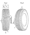
- the present invention relates to a pneumatic tire. More specifically, the invention relates to a pneumatic tire improved in or relating to both of the cornering performance on dry pavements (hereinafter referred to as the dry-condition cornering performance) and the water removing or repelling characteristic both in straight running service and in cornering service of the tire on wet pavements (herein strictlyafter referred to as the wet-condition performance).
- tires having such tread pattern are mounted on vehicles in a manner such that the side of the tire in which the groove area ratio on the tread surface is relatively small and the stiffness on the tread surface is relatively high is disposed at an outer side of the vehicles.
- the load on tires tend, due to the centrifugal force generated by the cornering of the vehicles, to concentrate on tires located on the side opposite to the side to which the vehicles are turned, the tread surface on the side of the tire having a relatively high stiffness can stand the concentration of load.
- a problem is indicated of the above tires such that upon cornering of vehicles on wet pavements, the water repelling characteristic lowers in the tread region having a relatively small groove area ratio.
- Japanese patent application Kokai publication No. 61-98601 proposes to attain an improvement in or relating to the water removing characteristic upon cornering, by providing a tire having a fletch- or herringbone-type tread pattern which comprises a plurality of straight-linear main grooves extending in the circumferential direction of the tire and a plurality of subgrooves bridging the main grooves and extending toward shoulder ends of the tire and in which the subgrooves include an angled or a curved portion convex in the direction of rotation of the tire, the tire being mounted on a vehicle with the angled or curved portion of sub- grooves disposed on an outer side of the vehicle.
- This tire can exhibit an improved wet-condition performance not only upon cornering or turning but also in straight running of vehicles.
- it has been impossible to obtain a satisfactory dry-condition cornering performance by way only of providing a herringbone-type tread pattern such as above.
- Objects of the present invention center upon providing a pneumatic tire improved in or relating to both of the wet-condition performance in straight running and upon cornering and the dry-condition cornering performance, substantially solely by way of providing a novel tread pattern to the tire.
- the pneumatic tire to attain the above object according to the invention has a fletch- or herringbone-type tread pattern which comprises a plurality of straight-linear main grooves extending in the circumferential direction of the tire and a plurality of subgrooves bridging the main grooves and extending to the shoulder ends of the tire and in which the subgrooves have in a central region of the width of the ground-contact area of the tread an angled or a curved portion convex in the direction of rotation of the tire.
- This tire is structured so that when it is mounted on a vehicle, the angled or curved portion in the subgrooves is located off the center of the contact area width toward an outer side of the vehicle by a distance within a range of 5 to 15 % of the contact area width of the tread.
- sub-grooves extending between the angled or curved portion and the shoulder end on an outer side of the vehicle have an angle of inclination ⁇ o relative to the tire circumferential direction
- subgrooves extending between the angled or curved portion and the shoulder end on an inner side of the vehicle have an inclination angle ⁇ i also relative to the tire circumferential direction
- the angles of inclination ⁇ o and ⁇ i have a ⁇ o/ ⁇ i ratio which exceeds 1.1 but does not reach 1.5.
- the pneumatic tire according to the present invention has a tread pattern which comprises a plurality of straight-linear main grooves 1 extending in the circumferential direction of the tire E-E′ and a plurality of subgrooves 2 bridging or connecting the main grooves 1 to one another and extending to the shoulder ends of the tire.
- This tread pattern comes under a fletch- or herringbone-type one in that the subgrooves 2 have, in a central region of the width D of the ground-contact area of the tread, angled or curved portions c which are convex in the direction in which the tire is to be rotated.
- the curved portions c in the subgrooves 2 are arranged so that in the condition of the tire of being mounted on a vehicle, they are located off the center CL of the contact area width D of the tread toward an outer side of the tire by a distance within a range of 5 to 15 % of the contact area width D. It is not always necessary that the curved portions c are disposed in alignment with a main groove 1, and they may be in an offset arrangement as best seen from Figs. 1 and 3.
- Subgrooves 2 extend toward the left or the right shoulder end, crossing main grooves 1 at an inclination and depicting either straight lines or moderately curved lines.
- the subgrooves 2 are formed to comprise a moderately curved line.
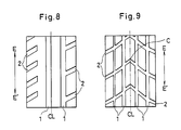
- the angle of inclination ⁇ o of the subgrooves 2 extending between the curved portion c and the shoulder end of the tire on an outer side of a vehicle, relative to the tire circumferential direction E-E′ is set to exceed the comparable angle ⁇ i of the subgrooves 2 extending between the curved portion c and the shoulder end of the tire on an inner side of the vehicle, also relative to the tire circumferential direction E-E′. More specifically, it is set that the ratio of the inclination angles ⁇ o to ⁇ i, ⁇ o/ ⁇ i-, exceeds 1.1 but does not reach 1.5.
- the inclination angles ⁇ o and ⁇ i mean as follows: Where subgrooves between curved portion c and shoulder ends are straight linear, the angle ⁇ o is the angle taken by a straight line depicted to connect together the center of a subgroove at the curved portion c and the center of the subgroove at the shoulder end on the outer side of a vehicle, relative to the tire center line CL, and a same as this applies to the angle ⁇ i except that the shoulder end is in this case on the inner side of the vehicle.
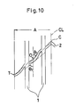
- the angle ⁇ o means 1/2 of the sum of an angle ⁇ 1 taken by a first straight line (shown by a dot-dash line in Fig. 10) depicted to connect together the center of a subgroove at the curved portion and the center of the subgroove at the shoulder end T on the outer side of the vehicle, relative to the tire center line CL, and an angle ⁇ 2 of the tangent (shown by a broken line in Fig. 10) on the point of a convex portion in the subgroove corresponding to the middle point O of the first straight line (the dot-dash line in Fig. 10), relative to the tire center line CL.
- a same as above applies to the angle ⁇ i except that the shoulder end is in this case on the inner side of the vehicle.
- the width D of the ground-contact area of the tread means the footprint width at the inflation pressure and under a load of 80 % of the maximum load prescribed in the standards defined by JATMA (Japan Automobile Tire Manufacturers Association).
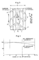
- the angled or curved portions c in the subgrooves 2 are formed off the tread center CL by a distance within a range of 5 to 15 % of the contact area width D. According to this arrangement of the curved portions c in the tread or tread pattern, it is possible to let the tire exhibit a remarkable water repelling characteristic not only when the tire is run straight but also when it is cornered at a slip angle of 2 to 4°, on wet road surfaces.
- the wet-condition performances are shown by indices obtained by taking as 100 the water repelling characteristic value found of a tire having a value of 0 (zero) for the degree of off-centering of the curved portions c in subgrooves relative to the tread center L, when this tire was run straight.
- tires having a degree of the off-centering of the curved portion c within a range of 5 to 15 % of the contact area width D of the tread can exhibit an improved water repelling characteristic at the time of cornering of the tire, without a considerable sacrifice caused to the comparable characteristic at the time of straight running, in comparison to tires having a degree of the off-centering outside the above range.
- the load on the tires moves toward left due to the centrifugal force generated by the turning of the vehicle, so that the tread contacts the ground or pavement surface in a state of being compressed toward a left half area portion thereof.
- the degree of compression of the tread is more conspicuous with the tire on the left side of the vehicle than the tire on the other vehicle side. Therefore, the curved portions c in the subgrooves 2 in the left-side tire come to be located about the center of the tread pattern as shwon in Fig. 6, so that removal of water can smoothly take place toward the left and the right sides of the curved portions c, whereby a desirable effect of water removal can be obtained.
- the right-hand tire prints a tread pattern as shown in Fig.
- the ratio, ⁇ o/ ⁇ i, of the inclination angle ⁇ o of subgrooves extending between the curved portion c and the shoulder end on an outer side of the vehicle to the comparable angle ⁇ i of subgrooves extending between the curved portion c and the shoulder end on an inner side of the vehicle is greater than 1.1 but is smaller than 1.5.
- blocks located on an outer side of the vehicle can have a greater rigidity to lateral forces than blocks located on an inner side of the vehicle, so that the dry-condition cornering performance can be improved, and yet this can be attained without lowering the wet-condition performance at any considerable extent.
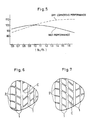
- Fig. 5 shows the data on the dry-condition cornering performance and the wet-condition performance, determined of tires having 8 % of the contact area width D of the tread for the degree of off-centering of the curved portions c in subgrooves 2 from the tread center CL to an outer side of a vehicle and having different ⁇ o/ ⁇ i ratio.
- the dry-condition cornering performance values and the wet-condition performance values are shown by indices (performance indices) obtained by taking as 100 the comparable values found of a tire having a value of 1.0 for the above ⁇ o/ ⁇ i ratio.
- tires having a ⁇ o/ ⁇ i ratio lying within the range of 1.1 to 1.5, both exclusive, can exhibit a remarkably improved dry-condition cornering performance maintaining a certain level of the wet-condition performance substantially unchanged, when compared with tires having a ⁇ o/ ⁇ i ratio not lying within the above range.
- the present invention further, it is contemplated to suppress the degree of discontinuity between blocks and grooves and yet maintain the wet-condition performance to be as high as possible, and also to let the tire exhibit a desirable dry-condition cornering performance and a high block rigidity, and to this end, preferably it should be met that the groove area ratio b in a contact region shown at B in Fig.
- the groove area ratio b in the contact region B is less than 30 %.
- the above groove area ratios a and b mean ratios in percentage (%) of groove areas to the sum of the contact area and the groove area in the contact regions A and B.
- the tires were mounted on four-wheel cars of Japanese origin, and under the conditions of an inflation pressure of 2.1 kgf/cm2 and a running velocity of 60 km/hour, running tests of the tires on actual cars were operated to determine each of the wet-condition straight running performance, the wet-condition cornering performance and the dry-condition cornering performance by a feeling evaluation method. Further, the tires were mounted on the cars with the convexity of curved portions c in subgrooves arranged to correspond to the direction of rotation of tires and located on an outer side of the cars.
- the performance data found are shown in terms of indices with the data found of the Comparative Tire II taken as 100, and larger indices mean more desirable results, applicable to both of the dry-condition performance and the wet-condition performance.
- tread pattern the one shown in Fig. 8 contact area width D of the tread, and the groove area ratios a and b: same as in the above Tire of the Invention I
- tread pattern the one shown in Fig. 9 ⁇ o, ⁇ i and ⁇ o/ ⁇ i ratio: same as in the Tire of the Invention I degree of off-centering of curved portions in sub-grooves [in percentage (%) to the contact area width D of the tread]: 0 % contact area width D of the tread: 150 mm contact region B: 45 mm groove area ratio b: 35 % groove area ratio a: 35 % b/a : 1.0
- tread pattern the one shown in Fig. 9 ⁇ o, ⁇ i and ⁇ o/ ⁇ i ratio: same as in the Tire of the Invention I degree of off-centering of curved portions in subgrooves [in percentage (%) to the contact area width D of the tread]: 0 % contact area width D of the tread: 150 mm contact region B: 45 mm groove area ratio a: 35 % groove area ratio b: 25 % b/a: 0.71 Table 1 Comparative Tires Tire of the Invention I II III I groove area ratio b 25 % 35 % 25 % 25 % groove area ratio a 35 % 35 % 35 % 35 % % b/a 0.71 1 0.71 0.71 degree of off-centering ---- 0 0 8 % dry-condition cornering performance 105 100 105 105 wet-condition cornering performance 96 100 98 107 wet-condition straight running performance 96 100 100 99
- the Tire of the Invention I has a wet-condition straight running performance which is substantially comparable to those of the Comparative Tires II and III, a dry-condition cornering performance which is comparable to those of the Comparative Tires I and III and exceeds the performance of the Comparative Tire II, and a wet-condition cornering performance which greatly exceeds those of Comparative Tires I, II and III.
- Table 2 Comparative Tire IV Tire of the Invention II Comparative Tire V ⁇ o 55° 65° 90° ⁇ i 55° 55° 55° ⁇ o/ ⁇ i 1.0 1.2 1.5 dry-condition cornering performance 100 107 110 Wet-condition performance 100 100 93
- the Tire of the Invention II has a wet-condition performance and a dry-condition cornering performance each of which is remarkable, that with respect to the wet-condition performance, the Comparative Tire V is consdierably inferior to both of the Tire of the Invention II and the Comparative Tire IV, and that with respect to the dry-condition cornering performance, the Comparative Tire IV is considerably inferior to both of the Tire of the Invention II and the Comparative Tire V.
Landscapes
- Engineering & Computer Science (AREA)
- Mechanical Engineering (AREA)
- Tires In General (AREA)
Applications Claiming Priority (4)
| Application Number | Priority Date | Filing Date | Title |
|---|---|---|---|
| JP152167/88 | 1988-06-22 | ||
| JP15216788 | 1988-06-22 | ||
| JP250838/88 | 1988-10-06 | ||
| JP63250838A JPH0270506A (ja) | 1988-06-22 | 1988-10-06 | 空気入りタイヤ |
Publications (3)
| Publication Number | Publication Date |
|---|---|
| EP0347817A2 true EP0347817A2 (de) | 1989-12-27 |
| EP0347817A3 EP0347817A3 (de) | 1991-01-23 |
| EP0347817B1 EP0347817B1 (de) | 1994-02-09 |
Family
ID=26481156
Family Applications (1)
| Application Number | Title | Priority Date | Filing Date |
|---|---|---|---|
| EP89111149A Expired - Lifetime EP0347817B1 (de) | 1988-06-22 | 1989-06-20 | Luftreifen |
Country Status (6)
| Country | Link |
|---|---|
| US (1) | US5152852A (de) |
| EP (1) | EP0347817B1 (de) |
| JP (1) | JPH0270506A (de) |
| AU (1) | AU625417B2 (de) |
| CA (1) | CA1330518C (de) |
| DE (1) | DE68912974T2 (de) |
Cited By (3)
| Publication number | Priority date | Publication date | Assignee | Title |
|---|---|---|---|---|
| EP0479763A3 (en) * | 1990-10-04 | 1992-10-28 | Semperit Reifen Aktiengesellschaft | Pneumatic tyre for vehicles |
| US5372171A (en) * | 1992-02-05 | 1994-12-13 | The Yokohama Rubber Co., Ltd. | Pneumatic tire with asymmetrical tread shoulders |
| FR3123249A1 (fr) * | 2021-05-31 | 2022-12-02 | Compagnie Generale Des Etablissements Michelin | Pneumatique pour un véhicule poids lourd à usage mixte à faible bruit de roulage |
Families Citing this family (28)
| Publication number | Priority date | Publication date | Assignee | Title |
|---|---|---|---|---|
| JPH01314609A (ja) * | 1988-06-15 | 1989-12-19 | Yokohama Rubber Co Ltd:The | 空気入りタイヤ |
| USD324839S (en) | 1990-01-22 | 1992-03-24 | The Goodyear Tire & Rubber Company | Tire tread and buttress |
| US5435364A (en) * | 1990-12-28 | 1995-07-25 | Sumitomo Rubber Industries, Ltd. | Pneumatic radial tire with four main grooves |
| CA2058848A1 (en) * | 1991-07-26 | 1993-01-27 | Maurice Graas | Tread with multiple pitching |
| US5363895A (en) * | 1993-06-23 | 1994-11-15 | The Goodyear Tire & Rubber Company | Bias ply pneumatic tire |
| IT1276320B1 (it) * | 1994-02-22 | 1997-10-28 | Pirelli | Pneumatico per veicoli da trasporto medio/pesante con battistrada di tipo universale |
| AT402178B (de) * | 1994-02-25 | 1997-02-25 | Semperit Ag | Laufstreifen für einen fahrzeugluftreifen |
| US5407005A (en) * | 1994-04-04 | 1995-04-18 | The Goodyear Tire & Rubber Company | Tread for a tire |
| USD382521S (en) * | 1995-11-08 | 1997-08-19 | The Goodyear Tire & Rubber Company | Tire tread |
| USD415982S (en) | 1995-12-18 | 1999-11-02 | The Goodyear Tire & Rubber Company | Tire tread |
| USD381607S (en) * | 1996-04-17 | 1997-07-29 | The Goodyear Tire & Rubber Company | Tire tread |
| USD384607S (en) * | 1996-04-18 | 1997-10-07 | The Goodyear Tire & Rubber Company | Tire tread |
| USD386471S (en) * | 1996-05-31 | 1997-11-18 | The Goodyear Tire & Rubber Company | Tire tread |
| USD397648S (en) | 1996-07-19 | 1998-09-01 | The Goodyear Tire & Rubber Company | Tire tread |
| USD403281S (en) | 1998-02-13 | 1998-12-29 | The Goodyear Tire & Rubber Company | Tire tread |
| USD467535S1 (en) | 2001-05-23 | 2002-12-24 | The Yokohama Rubber Co., Ltd. | Automobile tire |
| GB0515750D0 (en) | 2005-07-30 | 2005-09-07 | Dyson Technology Ltd | Drying apparatus |
| GB0515749D0 (en) | 2005-07-30 | 2005-09-07 | Dyson Technology Ltd | Drying apparatus |
| GB0515754D0 (en) | 2005-07-30 | 2005-09-07 | Dyson Technology Ltd | Drying apparatus |
| GB2428569B (en) * | 2005-07-30 | 2009-04-29 | Dyson Technology Ltd | Dryer |
| GB0515744D0 (en) | 2005-07-30 | 2005-09-07 | Dyson Technology Ltd | Dryer |
| GB2434094A (en) | 2006-01-12 | 2007-07-18 | Dyson Technology Ltd | Drying apparatus with sound-absorbing material |
| FR2904790B1 (fr) * | 2006-08-08 | 2008-10-10 | Michelin Soc Tech | Sculpture de bande de roulement pour vehicules de transport de charges lourdes. |
| EP2621740B1 (de) * | 2010-09-29 | 2016-12-21 | Pirelli Tyre S.p.A. | Leistungsstarker regenreifen |
| JP5873457B2 (ja) * | 2013-04-12 | 2016-03-01 | 住友ゴム工業株式会社 | 空気入りタイヤ |
| USD782961S1 (en) * | 2015-06-10 | 2017-04-04 | Bridgestone Corporation | Tread portion of an automobile tire |
| JP1539609S (de) * | 2015-06-10 | 2015-12-07 | ||
| CN111559206B (zh) * | 2019-02-13 | 2023-05-26 | 住友橡胶工业株式会社 | 轮胎 |
Family Cites Families (8)
| Publication number | Priority date | Publication date | Assignee | Title |
|---|---|---|---|---|
| GB1514473A (en) * | 1975-05-15 | 1978-06-14 | Michelin & Cie | Pneumatic tyres |
| FR2452391A1 (fr) * | 1979-03-27 | 1980-10-24 | Kleber Colombes | Pneumatique pour vehicule |
| JPS6198601A (ja) * | 1984-10-22 | 1986-05-16 | Yokohama Rubber Co Ltd:The | 4輪車両の空気入りタイヤ配置構造 |
| JPS62175204A (ja) * | 1986-01-29 | 1987-07-31 | Yokohama Rubber Co Ltd:The | 乗用車用空気入りラジアルタイヤ |
| US4732194A (en) * | 1986-04-17 | 1988-03-22 | The Yokohama Rubber Co., Ltd. | Asymmetric tire and tread |
| JPS6452507A (en) * | 1987-05-08 | 1989-02-28 | Bridgestone Corp | Pneumatic tire pair |
| US4877072A (en) * | 1987-12-17 | 1989-10-31 | The Goodyear Tire & Rubber Company | Tread for left and right vehicle tires |
| JPH01314609A (ja) * | 1988-06-15 | 1989-12-19 | Yokohama Rubber Co Ltd:The | 空気入りタイヤ |
-
1988
- 1988-10-06 JP JP63250838A patent/JPH0270506A/ja active Pending
-
1989
- 1989-06-19 CA CA000603259A patent/CA1330518C/en not_active Expired - Fee Related
- 1989-06-20 EP EP89111149A patent/EP0347817B1/de not_active Expired - Lifetime
- 1989-06-20 DE DE68912974T patent/DE68912974T2/de not_active Expired - Fee Related
- 1989-06-21 AU AU36684/89A patent/AU625417B2/en not_active Ceased
-
1991
- 1991-06-20 US US07/722,409 patent/US5152852A/en not_active Expired - Fee Related
Cited By (4)
| Publication number | Priority date | Publication date | Assignee | Title |
|---|---|---|---|---|
| EP0479763A3 (en) * | 1990-10-04 | 1992-10-28 | Semperit Reifen Aktiengesellschaft | Pneumatic tyre for vehicles |
| US5372171A (en) * | 1992-02-05 | 1994-12-13 | The Yokohama Rubber Co., Ltd. | Pneumatic tire with asymmetrical tread shoulders |
| FR3123249A1 (fr) * | 2021-05-31 | 2022-12-02 | Compagnie Generale Des Etablissements Michelin | Pneumatique pour un véhicule poids lourd à usage mixte à faible bruit de roulage |
| WO2022254121A1 (fr) * | 2021-05-31 | 2022-12-08 | Compagnie Generale Des Etablissements Michelin | Pneumatique pour un véhicule poids lourd à usage mixte à faible bruit de roulage |
Also Published As
| Publication number | Publication date |
|---|---|
| EP0347817A3 (de) | 1991-01-23 |
| AU625417B2 (en) | 1992-07-09 |
| CA1330518C (en) | 1994-07-05 |
| JPH0270506A (ja) | 1990-03-09 |
| DE68912974D1 (de) | 1994-03-24 |
| EP0347817B1 (de) | 1994-02-09 |
| AU3668489A (en) | 1990-01-04 |
| DE68912974T2 (de) | 1994-05-19 |
| US5152852A (en) | 1992-10-06 |
Similar Documents
| Publication | Publication Date | Title |
|---|---|---|
| EP0347817B1 (de) | Luftreifen | |
| EP0339335B1 (de) | Luftreifen | |
| EP3388257B1 (de) | Reifen | |
| EP3260308B1 (de) | Reifen | |
| EP2199111B1 (de) | Luftreifen mit Lamellen | |
| EP0256794B1 (de) | Gürtelreifen | |
| EP3398793B1 (de) | Reifen | |
| EP1645441B1 (de) | Luftreifen | |
| EP0524561B1 (de) | Reifenlauffläche | |
| EP1176034B1 (de) | Luftreifen | |
| US6374884B2 (en) | Heavy duty tire including narrow groove | |
| EP0338491B1 (de) | Luftreifen | |
| EP3575110B1 (de) | Reifen | |
| EP0798137A1 (de) | Radialer luftreifen | |
| EP4173846B1 (de) | Luftreifen | |
| EP4000962B1 (de) | Reifen | |
| EP1676725B1 (de) | Luftreifen | |
| EP3960503B1 (de) | Reifen | |
| EP1010551B1 (de) | Luftreifen | |
| JPS6364802A (ja) | 空気入りタイヤ | |
| EP2316664A1 (de) | Luftreifen | |
| EP3988336B1 (de) | Reifen | |
| EP4079540B1 (de) | Reifen | |
| EP3744536B1 (de) | Reifen | |
| EP3686036B1 (de) | Reifenlauffläche |
Legal Events
| Date | Code | Title | Description |
|---|---|---|---|
| PUAI | Public reference made under article 153(3) epc to a published international application that has entered the european phase |
Free format text: ORIGINAL CODE: 0009012 |
|
| AK | Designated contracting states |
Kind code of ref document: A2 Designated state(s): DE FR GB IT |
|
| PUAL | Search report despatched |
Free format text: ORIGINAL CODE: 0009013 |
|
| AK | Designated contracting states |
Kind code of ref document: A3 Designated state(s): DE FR GB IT |
|
| 17P | Request for examination filed |
Effective date: 19910607 |
|
| 17Q | First examination report despatched |
Effective date: 19920731 |
|
| GRAA | (expected) grant |
Free format text: ORIGINAL CODE: 0009210 |
|
| AK | Designated contracting states |
Kind code of ref document: B1 Designated state(s): DE FR GB IT |
|
| ITF | It: translation for a ep patent filed | ||
| REF | Corresponds to: |
Ref document number: 68912974 Country of ref document: DE Date of ref document: 19940324 |
|
| ET | Fr: translation filed | ||
| PLBE | No opposition filed within time limit |
Free format text: ORIGINAL CODE: 0009261 |
|
| STAA | Information on the status of an ep patent application or granted ep patent |
Free format text: STATUS: NO OPPOSITION FILED WITHIN TIME LIMIT |
|
| 26N | No opposition filed | ||
| PGFP | Annual fee paid to national office [announced via postgrant information from national office to epo] |
Ref country code: GB Payment date: 19950609 Year of fee payment: 7 Ref country code: FR Payment date: 19950609 Year of fee payment: 7 |
|
| PGFP | Annual fee paid to national office [announced via postgrant information from national office to epo] |
Ref country code: DE Payment date: 19950617 Year of fee payment: 7 |
|
| PG25 | Lapsed in a contracting state [announced via postgrant information from national office to epo] |
Ref country code: GB Effective date: 19960620 |
|
| GBPC | Gb: european patent ceased through non-payment of renewal fee |
Effective date: 19960620 |
|
| PG25 | Lapsed in a contracting state [announced via postgrant information from national office to epo] |
Ref country code: FR Effective date: 19970228 |
|
| PG25 | Lapsed in a contracting state [announced via postgrant information from national office to epo] |
Ref country code: DE Effective date: 19970301 |
|
| REG | Reference to a national code |
Ref country code: FR Ref legal event code: ST |
|
| PG25 | Lapsed in a contracting state [announced via postgrant information from national office to epo] |
Ref country code: IT Free format text: LAPSE BECAUSE OF NON-PAYMENT OF DUE FEES;WARNING: LAPSES OF ITALIAN PATENTS WITH EFFECTIVE DATE BEFORE 2007 MAY HAVE OCCURRED AT ANY TIME BEFORE 2007. THE CORRECT EFFECTIVE DATE MAY BE DIFFERENT FROM THE ONE RECORDED. Effective date: 20050620 |