EP0347576A2 - Well having means for expelling easy volatile impurities form underground water - Google Patents
Well having means for expelling easy volatile impurities form underground water Download PDFInfo
- Publication number
- EP0347576A2 EP0347576A2 EP89108646A EP89108646A EP0347576A2 EP 0347576 A2 EP0347576 A2 EP 0347576A2 EP 89108646 A EP89108646 A EP 89108646A EP 89108646 A EP89108646 A EP 89108646A EP 0347576 A2 EP0347576 A2 EP 0347576A2
- Authority
- EP
- European Patent Office
- Prior art keywords
- pressure
- well shaft
- receiving space
- air
- groundwater
- Prior art date
- Legal status (The legal status is an assumption and is not a legal conclusion. Google has not performed a legal analysis and makes no representation as to the accuracy of the status listed.)
- Granted
Links
- XLYOFNOQVPJJNP-UHFFFAOYSA-N water Substances O XLYOFNOQVPJJNP-UHFFFAOYSA-N 0.000 title claims abstract description 8
- 239000012535 impurity Substances 0.000 title claims abstract description 5
- 239000003673 groundwater Substances 0.000 claims abstract description 26
- 239000007788 liquid Substances 0.000 claims description 6
- 239000002689 soil Substances 0.000 claims description 3
- 239000007789 gas Substances 0.000 abstract 1
- 238000004140 cleaning Methods 0.000 description 2
- 239000000356 contaminant Substances 0.000 description 2
- 238000007796 conventional method Methods 0.000 description 2
- 238000000034 method Methods 0.000 description 2
- 238000000605 extraction Methods 0.000 description 1
- 229910052500 inorganic mineral Inorganic materials 0.000 description 1
- 239000011707 mineral Substances 0.000 description 1
Images
Classifications
-
- E—FIXED CONSTRUCTIONS
- E03—WATER SUPPLY; SEWERAGE
- E03B—INSTALLATIONS OR METHODS FOR OBTAINING, COLLECTING, OR DISTRIBUTING WATER
- E03B3/00—Methods or installations for obtaining or collecting drinking water or tap water
- E03B3/06—Methods or installations for obtaining or collecting drinking water or tap water from underground
- E03B3/08—Obtaining and confining water by means of wells
- E03B3/15—Keeping wells in good condition, e.g. by cleaning, repairing, regenerating; Maintaining or enlarging the capacity of wells or water-bearing layers
-
- B—PERFORMING OPERATIONS; TRANSPORTING
- B01—PHYSICAL OR CHEMICAL PROCESSES OR APPARATUS IN GENERAL
- B01D—SEPARATION
- B01D19/00—Degasification of liquids
- B01D19/0005—Degasification of liquids with one or more auxiliary substances
-
- B—PERFORMING OPERATIONS; TRANSPORTING
- B09—DISPOSAL OF SOLID WASTE; RECLAMATION OF CONTAMINATED SOIL
- B09C—RECLAMATION OF CONTAMINATED SOIL
- B09C1/00—Reclamation of contaminated soil
- B09C1/005—Extraction of vapours or gases using vacuum or venting
-
- B—PERFORMING OPERATIONS; TRANSPORTING
- B09—DISPOSAL OF SOLID WASTE; RECLAMATION OF CONTAMINATED SOIL
- B09C—RECLAMATION OF CONTAMINATED SOIL
- B09C2101/00—In situ
Definitions
- the invention relates to a well for expelling volatile contaminants from the groundwater and the soil through which it flows by generating negative pressure in a well shaft driven into the area of the contaminated groundwater and supplying fresh air below the water level in the well shaft.
- the implementation of the above-mentioned method is made more difficult in cases in which confined groundwater, that is to say pressurized groundwater, has to be treated. This can occur in particular if mineral water, which is often under excess pressure, has to be cleaned via the well shaft.
- the invention has for its object to design the arrangement mentioned so that it can be operated properly even when the groundwater is tight.
- a fountain according to the invention in that the well shaft is closed at its upper end with a pressure receiving space, which fresh air can be supplied with a pressure compensating for the groundwater overpressure and in which the negative pressure generator forming the negative pressure in the well shaft is arranged.
- the pressure chamber which can be formed by a closure container placed on the well shaft opening, closes the well shaft from the outside, so that the fresh air supplied with equalizing pressure can create a water-free head region of the well shaft, in which the negative pressure, which is decisive for the cleaning effect, is then relative to the pressure prevailing in the well shaft, which is above atmospheric pressure.
- the air receiving space located below the liquid level, which is delimited from the liquid space of the well shaft by a sieve wall, the air receiving space can be connected via an air line to the pressure receiving space, in which fresh air is supplied to the compensation pressure.
- a float valve can expediently be arranged in the air line leading to the air-receiving space and / or in a suction shaft formed in front of the suction opening of the vacuum generator.
- compressed water can be used to create a water-free area at the top of the well shaft.
- the pressure is finally reduced to the compensation pressure value before the vacuum generator is put into operation and generates a vacuum in the upper well shaft area compared to the compensation pressure.
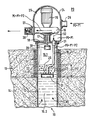
- the drawing shows a well shaft 10 reinforced in its upper end region 10.1 by means of non-perforated pipes 11 and in its lower region 10.2 by sieve pipes 12, which is carried out through an upper ground layer 13 which inhibits groundwater and into a lower ground layer 14 leading into groundwater.
- the groundwater is tense and thus flows into the well shaft 10 a pressure P1 that is greater than the atmospheric pressure Po.
- the arrangement for expelling volatile contaminants from the groundwater entering the well shaft 10 consists of a fan 16 operated by means of an electric motor 15 for generating a negative pressure in the upper well shaft area 10.1 free of the groundwater.
- An intake duct 17 is formed in front of the intake opening of the fan 16, which leads to an air intake opening formed in a cover wall 18 closing the outer opening of the well shaft 10.
- this cover wall 18 there is also an opening for an air line 19 formed by a hose, which leads to an air receiving space 21 formed below the groundwater level 20 formed in the well shaft.
- the air receiving space 21 is bounded at the top and to the side by a sieve wall 22, through the openings of which the air can rise from the air receiving space 21 in the form of air bubbles 23 to the liquid level 20.
- a container 24 is placed on the end wall 18 of the well shaft 10, in which the fan 16 with its drive motor 15 is arranged and which delimits a pressure receiving space 25.
- the container has a first opening for a fresh air line 26 and a second opening 27 for the exhaust air of the fan 16 serving as a vacuum generator.
- a pressure relief valve 28 is arranged in front of the second opening 27.
- the opening formed in the end wall 18 for the intake duct 17 of the fan 16 can be closed by a float valve, the float 29 of which is mounted in a longitudinally displaceable manner on a central guide rod 30.
- the air line 19 can also be closed in the area of the end wall 18 by a float valve 31.
- the pressure P1 given by the tensioned groundwater prevails in the deeper well shaft area 10.2.
- the suction pressure P2 of the fan 16 acts between the air receiving space 21 and the water level 20, as indicated in the drawing by a double arrow.
- Fresh air with a pressure Po + P1 is introduced into the pressure receiving space 25 through the fresh air line 26. This pressure is so measured that it compensates for the groundwater overpressure P1.
- the fresh air under this compensation pressure is directed in the direction of the arrow 32 under the action of the fan 16 through the air line 19 into the air receiving space 21.
- a pressure Po + P1-P2 forms in the well shaft area 10.1 free of groundwater under the suction effect of the fan 16.
- the pressure on the outlet side of the fan 16 is Po + P1 + P2.
- the air extraction arrangement can thus be operated with the desired and experience-based good cleaning action even in the case of tense groundwater. If the fan 16 is switched off and the fresh air supply is interrupted, the liquid level 20 can rise in the well shaft 10. Then the float valves 29, 31 prevent water from entering the area of the container 24. After creating a reason water-free upper shaft area 10.1 by temporarily introducing compressed air into this area, the starting conditions for operating the arrangement shown in the drawing can be restored at any time.
Landscapes
- Engineering & Computer Science (AREA)
- Environmental & Geological Engineering (AREA)
- Life Sciences & Earth Sciences (AREA)
- Chemical & Material Sciences (AREA)
- Health & Medical Sciences (AREA)
- Hydrology & Water Resources (AREA)
- Public Health (AREA)
- Water Supply & Treatment (AREA)
- Soil Sciences (AREA)
- Chemical Kinetics & Catalysis (AREA)
- Physical Water Treatments (AREA)
- Special Spraying Apparatus (AREA)
- Degasification And Air Bubble Elimination (AREA)
- Vaporization, Distillation, Condensation, Sublimation, And Cold Traps (AREA)
- Investigation Of Foundation Soil And Reinforcement Of Foundation Soil By Compacting Or Drainage (AREA)
- Extraction Or Liquid Replacement (AREA)
Abstract
Description
Die Erfindung betrifft einen Brunnen zum Austreiben leichtflüchtiger Verunreinigungen aus dem Grundwasser und dem von ihm durchströmten Erdreich durch Erzeugung von Unterdruck in einem bis in den Bereich des verunreinigten Grundwassers getriebenen Brunnenschacht und Zuleitung von Frischluft unterhalb des Wasserspiegels im Brunnenschacht.The invention relates to a well for expelling volatile contaminants from the groundwater and the soil through which it flows by generating negative pressure in a well shaft driven into the area of the contaminated groundwater and supplying fresh air below the water level in the well shaft.
Anordnungen der eingangs genannten Art sind bereits vorgeschlagen worden (z.B. DE-OS 36 25 488 der Antragstellerin). Im Gegensatz zu den herkömmlichen Verfahren, mit erheblichem Energieaufwand Druckluft in das einen Brunnenschacht umgebende Erdreich und/oder in das im Brunnenschacht angesammelte Grundwasser einzupressen, wird bei dieser Anordnung Luft allein unter der Wirkung eines im wasserfreien Bereich des Brunnenschachtes gebildeten Unterdruckes eingeleitet. Dabei hat sich gezeigt, daß hierbei mit relativ geringem Unterdruck überraschend große Mengen an leichtflüchtigen Verunreinigungen in gasförmigem Zustand abgesaugt werden können und ein beachtlich größerer Wirkungsgrad erzielt wird, als bei den erwähnten herkömmlichen Verfahren. Bei den herkömmlichen Verfahren werden durch die angewandten hohen Drücke Laminarströmungen abgerissen und Wirbel gebildet, welche den Wirkungsgrad der Anlagen erheblich vermindern.Arrangements of the type mentioned at the beginning have already been proposed (for example DE-OS 36 25 488 of the applicant). In contrast to the conventional methods of using a considerable amount of energy to press compressed air into the soil surrounding a well shaft and / or into the groundwater accumulated in the well shaft, in this arrangement air is introduced only under the effect of a negative pressure formed in the water-free area of the well shaft. It has been shown that surprisingly large amounts of volatile impurities can be extracted in a gaseous state with a relatively low negative pressure and a considerably greater efficiency is achieved than with the conventional methods mentioned. In the conventional processes, laminar flows are broken off and vortices are formed due to the high pressures used, which considerably reduce the efficiency of the systems.
Die Durchführung des vorstehend genannten Verfahrens wird in Fällen erschwert, in denen gespanntes Grundwasser, also unter Überdruck stehendes Grundwasser, behandelt werden muß. Dieser Fall kann insbesondere dann auftreten, wenn über den Brunnenschacht Mineralwasser gereinigt werden muß, das häufig unter Überdruck steht. Der Erfindung liegt die Aufgabe zugrunde, die eingangs genannte Anordnung so auszubilden, daß sie auch bei gespanntem Grundwasser einwandfrei betrieben werden kann.The implementation of the above-mentioned method is made more difficult in cases in which confined groundwater, that is to say pressurized groundwater, has to be treated. This can occur in particular if mineral water, which is often under excess pressure, has to be cleaned via the well shaft. The invention has for its object to design the arrangement mentioned so that it can be operated properly even when the groundwater is tight.
Die gestellte Aufgabe wird mit einem Brunnen erfindungsgemäß dadurch gelöst, daß der Brunnenschacht an seinem oberen Ende mit einem Druckaufnahmeraum abgeschlossen ist, welchem Frischluft mit einem den Grundwasserüberdruck kompensierenden Druck zuführbar ist und in welchem der den Unterdruck im Brunnenschacht bildende Unterdruckerzeuger angeordnet ist.The object is achieved with a fountain according to the invention in that the well shaft is closed at its upper end with a pressure receiving space, which fresh air can be supplied with a pressure compensating for the groundwater overpressure and in which the negative pressure generator forming the negative pressure in the well shaft is arranged.
Durch den Druckaufnahmeraum, der durch einen auf die Brunnenschachtöffnung aufgesetzten Abschlußbehälter gebildet sein kann, wird der Brunnenschacht nach außen abgeschlossen, so daß durch die mit Ausgleichsdruck zugeführte Frischluft ein wasserfreier Kopfbereich des Brunnenschachtes geschaffen werden kann, in welchem dann der für die Reinigungswirkung entscheidende Unterdruck relativ zu dem im Brunnenschacht herrschenden Druck, der über dem atmosphärischen Druck liegt, geschaffen werden kann. Bei der bevorzugten, bereits vorgeschlagenen Ausbildung eines unterhalb des Flüssigkeitsspiegels befindlichen Luftaufnahmeraumes, der vom Flüssigkeitsraum des Brunnenschachtes durch eine Siebwandung abgegrenzt ist, kann der Luftaufnahmeraum über eine Luftleitung mit dem Druckaufnahmeraum verbunden sein, in welch letzteren Frischluft mit dem Kompensationsdruck zugeführt wird.The pressure chamber, which can be formed by a closure container placed on the well shaft opening, closes the well shaft from the outside, so that the fresh air supplied with equalizing pressure can create a water-free head region of the well shaft, in which the negative pressure, which is decisive for the cleaning effect, is then relative to the pressure prevailing in the well shaft, which is above atmospheric pressure. In the Preferred, already proposed design of an air receiving space located below the liquid level, which is delimited from the liquid space of the well shaft by a sieve wall, the air receiving space can be connected via an air line to the pressure receiving space, in which fresh air is supplied to the compensation pressure.
Damit in Stillstandszeiten der Anordnung kein gespanntes Grundwasser in den Druckaufnahmeraum eindringen kann, können in der zum Luftaufnahmeraum führenden Luftleitung und/oder in einem vor der Ansaugöffnung des Unterdruckerzeugers ausgebildeten Ansaugschacht zweckmäßig ein Schwimmerventil angeordnet sein. Bei Wiederinbetriebnahme der Anordnung kann mit Hilfe von Druckluft zunächst wieder ein wasserfreier Bereich am oberen Ende des Brunnenschachtes geschaffen werden. Der Druck wird schließlich auf den Kompensationsdruckwert abgesenkt, bevor der Unterdruckerzeuger in Betrieb gesetzt wird und gegenüber dem Kompensationsdruck einen Unterdruck im oberen Brunnenschachtbereich erzeugt.So that no strained groundwater can penetrate into the pressure-receiving space during downtimes of the arrangement, a float valve can expediently be arranged in the air line leading to the air-receiving space and / or in a suction shaft formed in front of the suction opening of the vacuum generator. When the arrangement is put back into operation, compressed water can be used to create a water-free area at the top of the well shaft. The pressure is finally reduced to the compensation pressure value before the vacuum generator is put into operation and generates a vacuum in the upper well shaft area compared to the compensation pressure.
Nachfolgend wird ein Ausführungsbeispiel einer erfindungsgemäß ausgebildeten Anordnung anhand der beiliegenden Zeichnung näher erläutert.An exemplary embodiment of an arrangement designed according to the invention is explained in more detail below with reference to the accompanying drawing.
Die Zeichnung zeigt einen in seinem oberen Endbereich 10.1 mittels ungelochter Rohre 11 und in seinem tieferen Bereich 10.2 mittels Siebrohren 12 armierten Brunnenschacht 10, der durch eine das Grundwasser hemmende obere Bodenschicht 13 bis in eine Grundwasser führende untere Bodenschicht 14 hinein ausgeführt ist. Das Grundwasser ist gespannt und strömt somit in den Brunnenschacht 10 unter einem Druck P1, der größer ist als der Atmosphärendruck Po.The drawing shows a
Die Anordnung zum Austreiben leichtflüchtiger Verunreinigungen aus dem in den Brunnenschacht 10 eindringenden Grundwasser besteht aus einem mittels eines Elektromotors 15 betriebenen Ventilator 16 zur Erzeugung eines Unterdrucks im oberen grundwasserfreien Brunnenschachtbereich 10.1. Vor der Ansaugöffnung des Ventilators 16 ist ein Ansaugkanal 17 ausgebildet, der bis zu einer in einer die äußere Öffnung des Brunnenschachtes 10 verschließenden Abdeckwandung 18 ausgebildeten Luftansaugöffnung führt. In dieser Abdeckwandung 18 ist zusätzlich eine Öffnung für eine durch einen Schlauch gebildete Luftleitung 19 ausgebildet, die zu einem unterhalb des sich im Brunnenschacht bildenden Grundwasserspiegels 20 ausgebildeten Luftaufnahmeraum 21 führt. Der Luftaufnahmeraum 21 ist nach oben und nach der Seite durch eine Siebwandung 22 begrenzt, durch deren Öffnungen hindurch die Luft aus dem Luftaufnahmeraum 21 in Form von Luftbläschen 23 zum Flüssigkeitsspiegel 20 aufsteigen kann.The arrangement for expelling volatile contaminants from the groundwater entering the
Auf die Abschlußwandung 18 des Brunnenschachtes 10 ist ein Behälter 24 aufgesetzt, in welchem der Ventilator 16 mit seinem Antriebsmotor 15 angeordnet ist und der einen Druckaufnahmeraum 25 begrenzt. Der Behälter weist nach außen eine erste Öffnung für eine Frischluftleitung 26 und eine zweite Öffnung 27 für die Abluft des als Unterdruckerzeuger dienenden Ventilators 16 auf. Vor der zweiten Öffnung 27 ist ein Druckbegrenzungsventil 28 angeordnet.A
Die in der Abschlußwandung 18 ausgebildete Öffnung für den Ansaugkanal 17 des Ventilators 16 ist durch ein Schwimmerventil verschließbar, dessen Schwimmer 29 auf einer zentralen Führungsstange 30 längsverschiebbar gelagert ist. Auch die Luftleitung 19 ist im Bereich der Abschlußwandung 18 durch ein Schwimmerventil 31 verschließbar.The opening formed in the
Im tieferen Brunnenschachtbereich 10.2 herrscht der durch das gespannte Grundwasser gegebene Druck P1. Zwischen dem Luftaufnahmeraum 21 und dem Wasserspiegel 20 wirkt der Ansaugdruck P2 des Ventilators 16, wie in der Zeichnung durch einen Doppelpfeil angedeutet ist. Durch die Frischluftleitung 26 wird Frischluft mit einem Druck Po+P1 in den Druckaufnahmeraum 25 eingeleitet. Dieser Druck ist also so bemessen, daß durch ihn der Grundwasser-Überdruck P1 kompensiert wird. Die unter diesem Kompensationsdruck stehende Frischluft wird in Richtung des eingetragenen Pfeiles 32 unter der Wirkung des Ventilators 16 durch die Luftleitung 19 in den Luftaufnahmeraum 21 geleitet. In dem grundwasserfreien Brunnenschachtbereich 10.1 bildet sich unter der Saugwirkung des Ventilators 16 ein Druck Po+P1-P2. Der Druck auf der Ausgangsseite des Ventilators 16 beträgt Po+P1+P2.The pressure P1 given by the tensioned groundwater prevails in the deeper well shaft area 10.2. The suction pressure P2 of the
Mit Hilfe der Druckaufnahmekammer 25 läßt sich die Luftabsauganordnung also auch bei gespanntem Grundwasser mit der angestrebten und erfahrungsgemäß guten Reinigungswirkung betreiben. Wird der Ventilator 16 abgeschaltet und die Frischluftzufuhr unterbrochen, kann im Brunnenschacht 10 der Flüssigkeitsspiegel 20 ansteigen. Dann verhindern die Schwimmerventile 29, 31 ein Eindringen des Wassers in den Bereich des Behälters 24. Nach Schaffung eines grund wasserfreien oberen Schachtbereiches 10.1 durch vorübergehende Einleitung von Druckluft in diesen Bereich lassen sich aber jederzeit wieder die aus der Zeichnung ersichtlichen Ausgangsverhältnisse zum Betrieb der Anordnung herstellen.With the help of the pressure-receiving
Claims (5)
Priority Applications (1)
| Application Number | Priority Date | Filing Date | Title |
|---|---|---|---|
| AT89108646T ATE98313T1 (en) | 1988-06-23 | 1989-05-13 | WELLS FOR DRIVING VOLATILE POLLUTANTS FROM CONTAINED GROUNDWATER. |
Applications Claiming Priority (2)
| Application Number | Priority Date | Filing Date | Title |
|---|---|---|---|
| DE8808089U DE8808089U1 (en) | 1988-06-23 | 1988-06-23 | Wells for removing volatile contaminants from confined groundwater |
| DE8808089U | 1988-06-23 |
Publications (3)
| Publication Number | Publication Date |
|---|---|
| EP0347576A2 true EP0347576A2 (en) | 1989-12-27 |
| EP0347576A3 EP0347576A3 (en) | 1991-07-10 |
| EP0347576B1 EP0347576B1 (en) | 1993-12-08 |
Family
ID=6825288
Family Applications (1)
| Application Number | Title | Priority Date | Filing Date |
|---|---|---|---|
| EP89108646A Expired - Lifetime EP0347576B1 (en) | 1988-06-23 | 1989-05-13 | Well having means for expelling easy volatile impurities form underground water |
Country Status (5)
| Country | Link |
|---|---|
| US (1) | US4943305A (en) |
| EP (1) | EP0347576B1 (en) |
| AT (1) | ATE98313T1 (en) |
| DE (2) | DE8808089U1 (en) |
| ES (1) | ES2047057T3 (en) |
Cited By (2)
| Publication number | Priority date | Publication date | Assignee | Title |
|---|---|---|---|---|
| US5352276A (en) * | 1991-02-26 | 1994-10-04 | Sippican, Inc. | Water remediation |
| WO2015162527A1 (en) | 2014-04-23 | 2015-10-29 | Universita' Degli Studi Di Roma "La Sapienza" | Process, arrangement and plant for the clean-up of waters contaminated by chlorinated solvents, nitrates and sulfates |
Families Citing this family (38)
| Publication number | Priority date | Publication date | Assignee | Title |
|---|---|---|---|---|
| DE3910990C1 (en) * | 1989-04-05 | 1989-12-21 | Ieg - Industrie-Engineering Gmbh, 7410 Reutlingen, De | |
| DE9005565U1 (en) * | 1990-05-16 | 1990-07-19 | Frese, Hermann, 2808 Syke | Facility for purifying groundwater |
| DE4021814A1 (en) * | 1990-05-23 | 1991-11-28 | Ieg Ind Engineering Gmbh | ARRANGEMENT FOR GAS TREATMENT OF POLLUTED SOIL |
| DE4027304C2 (en) * | 1990-08-29 | 1993-12-09 | Ieg Ind Engineering Gmbh | Arrangement for expelling volatile contaminants from the groundwater |
| US5104554A (en) * | 1990-12-14 | 1992-04-14 | Aqua-Rid, Inc. | Removing radon by downhole sparging of air |
| USH1206H (en) | 1991-01-24 | 1993-07-06 | The United States Of America As Represented By The Secretary Of The Air Force | Cascade crossflow tower |
| US5389267A (en) * | 1991-05-10 | 1995-02-14 | The Board Of Trustees Of The Leland Stanford Junior University | In-situ vapor stripping for removing volatile organic compounds from groundwater |
| US5180503A (en) * | 1991-05-10 | 1993-01-19 | The Board Of Trustees Of The Leland Stanford Junior University | In-situ vapor stripping for removing volatile organic compounds from groundwater |
| US5169567A (en) * | 1991-10-03 | 1992-12-08 | Daugherty James J | Water aeration apparatus |
| DE4204991A1 (en) * | 1991-12-24 | 1993-07-01 | Ieg Ind Engineering Gmbh | METHOD AND DEVICE FOR INFLUENCING LIQUID IN THE GROUND |
| US5302286A (en) * | 1992-03-17 | 1994-04-12 | The Board Of Trustees Of The Leland Stanford Junior University | Method and apparatus for in situ groundwater remediation |
| US5439594A (en) * | 1993-06-23 | 1995-08-08 | Geraghty & Miller, Inc. | Method for subsurface vapor extraction |
| US5622450A (en) * | 1995-03-24 | 1997-04-22 | Grant, Jr.; Richard P. | Pressure extraction process for removing soil and groundwater contaminants |
| US6143177A (en) | 1995-04-11 | 2000-11-07 | Arcadis Geraghty & Miller, Inc. | Engineered in situ anaerobic reactive zones |
| US5855775A (en) * | 1995-05-05 | 1999-01-05 | Kerfoot; William B. | Microporous diffusion apparatus |
| USRE43350E1 (en) | 1995-05-05 | 2012-05-08 | Think Village-Kerfoot, Llc | Microporous diffusion apparatus |
| US6284133B1 (en) | 1995-11-13 | 2001-09-04 | Shell Oil Company | Bio aerator |
| US6007274A (en) * | 1997-05-19 | 1999-12-28 | Arcadis Geraghty & Miller | In-well air stripping, oxidation, and adsorption |
| US5979554A (en) * | 1997-10-27 | 1999-11-09 | Xerox Corporation | Vacuum application method and apparatus for removing liquid contaminants from groundwater |
| US6116816A (en) | 1998-08-26 | 2000-09-12 | Arcadis Geraghty & Miller, Inc. | In situ reactive gate for groundwater remediation |
| US6436285B1 (en) * | 1999-12-22 | 2002-08-20 | William B. Kerfoot | Laminated microporous diffuser |
| US8557110B2 (en) * | 2000-07-06 | 2013-10-15 | Thinkvillage-Kerfoot, Llc | Groundwater and subsurface remediation |
| US6582611B1 (en) | 2000-07-06 | 2003-06-24 | William B. Kerfoot | Groundwater and subsurface remediation |
| SE517821C2 (en) * | 2000-09-29 | 2002-07-16 | Tetra Laval Holdings & Finance | Method and apparatus for continuously venting a liquid |
| US6652893B2 (en) | 2001-07-09 | 2003-11-25 | William Berson | Machine and process for aerating and flavoring water |
| US7547388B2 (en) * | 2004-07-20 | 2009-06-16 | Think Village-Kerfoot, Llc | Superoxidant poiser for groundwater and soil treatment with in-situ oxidation-reduction and acidity-basicity adjustment |
| US7666316B2 (en) | 2004-07-20 | 2010-02-23 | Thinkvillage-Kerfoot, Llc | Permanganate-coated ozone for groundwater and soil treatment with in-situ oxidation |
| US8302939B2 (en) * | 2003-02-12 | 2012-11-06 | Thinkvillage-Kerfoot, Llc | Soil and water remediation system and method |
| US7442313B2 (en) * | 2003-08-27 | 2008-10-28 | Thinkvillage-Kerfoot, Llc | Environmental remediation method and system |
| US6913251B2 (en) | 2003-02-12 | 2005-07-05 | William B. Kerfoot | Deep well sparging |
| US7651611B2 (en) * | 2006-07-12 | 2010-01-26 | Thinkvillage-Kerfoot, Llc | Directional microporous diffuser and directional sparging |
| US7621696B2 (en) * | 2006-07-12 | 2009-11-24 | Thinkvillage-Kerfoot, Llc | Directional microporous diffuser and directional sparging |
| US7401767B2 (en) * | 2003-12-24 | 2008-07-22 | Kerfoot William B | Directional microporous diffuser and directional sparging |
| US8771507B2 (en) | 2003-12-24 | 2014-07-08 | Thinkvillage-Kerfoot, Llc | Directional microporous diffuser and directional sparging |
| US7569140B2 (en) * | 2005-11-10 | 2009-08-04 | Thinkvillage-Kerfoot, Llc | Directional spargewell system |
| US7820137B2 (en) * | 2006-08-04 | 2010-10-26 | Enerdel, Inc. | Lithium titanate and method of forming the same |
| US9694401B2 (en) | 2013-03-04 | 2017-07-04 | Kerfoot Technologies, Inc. | Method and apparatus for treating perfluoroalkyl compounds |
| CN104773831A (en) * | 2015-03-24 | 2015-07-15 | 中国林业科学研究院林业新技术研究所 | A reoxygenation device and reoxygenation method for artificial wetlands |
Family Cites Families (24)
| Publication number | Priority date | Publication date | Assignee | Title |
|---|---|---|---|---|
| GB979198A (en) * | 1963-06-24 | 1965-01-01 | Wilbur Herman Hine | Well apparatus |
| US3265370A (en) * | 1965-10-12 | 1966-08-09 | Gen Filter Co | Packaged unit water aeration and filtration apparatus |
| US3640516A (en) * | 1970-03-18 | 1972-02-08 | Metaframe Corp | Aerating device |
| US3920552A (en) * | 1973-06-28 | 1975-11-18 | Elkern Jr Kenneth F | Self-contained water treatment system |
| CH595516A5 (en) * | 1975-07-23 | 1978-02-15 | Sulzer Ag | |
| US4101607A (en) * | 1976-07-01 | 1978-07-18 | Pbi, Inc. | Apparatus for aerating a liquid |
| GB1601626A (en) * | 1977-03-09 | 1981-11-04 | Macourt Denis J C | Method of and apparatus for determining chemical components in an off-shore liquid |
| US4166086A (en) * | 1978-05-02 | 1979-08-28 | Wright Earl B | Aerator for live bait bucket |
| DE2835709B2 (en) * | 1978-08-16 | 1980-12-18 | Wilhelm Roediger Gmbh + Co, 6450 Hanau | System for cleaning polluted water |
| HU185894B (en) * | 1980-07-03 | 1985-04-28 | Imre Gyulavari | Apparatus for treating fluids |
| US4505813A (en) * | 1982-06-14 | 1985-03-19 | Norwalk Wastewater Equipment Company | Wastewater treatment plant |
| US4478765A (en) * | 1982-08-18 | 1984-10-23 | Tubbs Dean L | Apparatus for aerating water supplies |
| US4687494A (en) * | 1983-08-18 | 1987-08-18 | Escobal Peter R | Apparatus and method for pumping air |
| US4608163A (en) * | 1984-01-13 | 1986-08-26 | Yohe Thomas L | Apparatus for purification of contaminated groundwater |
| DE3437195C2 (en) * | 1984-10-10 | 1987-05-14 | Haftpflichtverband der Deutschen Industrie Versicherungsverein auf Gegenseitigkeit, 3000 Hannover | Process for removing volatile liquids from contaminated soil and/or groundwater |
| US4741825A (en) * | 1985-12-18 | 1988-05-03 | Aeration Industries, Inc. | Mobile vortex shield |
| DE3601490A1 (en) * | 1986-01-20 | 1987-07-30 | Hoelter Heinz | Treatment of contaminated soils |
| US4749497A (en) * | 1986-01-21 | 1988-06-07 | Chemical Separation Technology, Inc. | Method and apparatus for treatment of acidic water |
| DE3625488C2 (en) * | 1986-04-22 | 1994-09-22 | Ieg Ind Engineering Gmbh | Device for expelling volatile impurities from liquids |
| ES2023839T5 (en) * | 1986-04-22 | 1995-08-16 | Ieg Ind Engineering Gmbh | PROVISION FOR THE EXTRACTION OF SLIGHTLY VOLATILE IMPURITIES FROM LIQUIDS. |
| DE3626145A1 (en) * | 1986-04-30 | 1987-11-12 | Ieg Ind Engineering Gmbh | Method and arrangement for driving out volatile contaminants from the soil |
| US4710324A (en) * | 1986-11-28 | 1987-12-01 | Galdino Vesnaver | Water aerating device |
| DE3811962C1 (en) * | 1988-04-11 | 1989-02-16 | Ieg - Industrie-Engineering Gmbh, 7410 Reutlingen, De | Arrangement for expelling highly volatile impurities from ground water |
| DE3805200C1 (en) * | 1988-02-19 | 1988-09-29 | Ieg - Industrie-Engineering Gmbh, 7410 Reutlingen, De | Arrangement for expelling readily volatile impurities from groundwater |
-
1988
- 1988-06-23 DE DE8808089U patent/DE8808089U1/en not_active Expired
-
1989
- 1989-05-13 DE DE89108646T patent/DE58906342D1/en not_active Expired - Fee Related
- 1989-05-13 EP EP89108646A patent/EP0347576B1/en not_active Expired - Lifetime
- 1989-05-13 ES ES89108646T patent/ES2047057T3/en not_active Expired - Lifetime
- 1989-05-13 AT AT89108646T patent/ATE98313T1/en not_active IP Right Cessation
- 1989-05-26 US US07/359,096 patent/US4943305A/en not_active Expired - Fee Related
Cited By (2)
| Publication number | Priority date | Publication date | Assignee | Title |
|---|---|---|---|---|
| US5352276A (en) * | 1991-02-26 | 1994-10-04 | Sippican, Inc. | Water remediation |
| WO2015162527A1 (en) | 2014-04-23 | 2015-10-29 | Universita' Degli Studi Di Roma "La Sapienza" | Process, arrangement and plant for the clean-up of waters contaminated by chlorinated solvents, nitrates and sulfates |
Also Published As
| Publication number | Publication date |
|---|---|
| DE58906342D1 (en) | 1994-01-20 |
| US4943305A (en) | 1990-07-24 |
| DE8808089U1 (en) | 1988-10-06 |
| EP0347576A3 (en) | 1991-07-10 |
| ES2047057T3 (en) | 1994-02-16 |
| EP0347576B1 (en) | 1993-12-08 |
| ATE98313T1 (en) | 1993-12-15 |
Similar Documents
| Publication | Publication Date | Title |
|---|---|---|
| EP0347576B1 (en) | Well having means for expelling easy volatile impurities form underground water | |
| DE4027304C2 (en) | Arrangement for expelling volatile contaminants from the groundwater | |
| DE1761617C3 (en) | Method for cleaning a filter device designed as a candle filter with hanging filter candles and device for carrying out the method | |
| DE3625488C2 (en) | Device for expelling volatile impurities from liquids | |
| EP0242665B2 (en) | Apparatus for the expulsion of light volatile pollutants from liquids | |
| DE2727988A1 (en) | METHOD FOR SEALING THE SPACE BETWEEN A WALL AND AN OPPOSITE SURFACE, AND DEVICES FOR PERFORMING THE METHOD AND APPLICATION OF METHODS AND DEVICES | |
| DE2743530B2 (en) | Device for cleaning large surface textures, in particular carpets and carpeting | |
| DE2804733A1 (en) | DEVICE FOR REPLACING OIL | |
| DE69200346T2 (en) | Improvements in vacuum sewage systems. | |
| DE3842740A1 (en) | Process for removing impurities from groundwater and a well for carrying out the process | |
| DE3931013C2 (en) | Arrangement for expelling volatile contaminants from the groundwater | |
| DE2143595A1 (en) | Coke oven door cleaning - by high-pressure water spray nozzles in extractor cowl | |
| DE69504214T2 (en) | Control method and system for avoiding suction back in turbine-driven dental treatment instruments | |
| DE3931011A1 (en) | Well shaft filter cleaning for below ground filters - has tubes sunk parallel to shaft connected in pump circuit for forced cleaning with provision for adding materials to flow | |
| DE4444641C1 (en) | Air=pulsating settling machine for processing minerals | |
| DE4243303C1 (en) | Process for cleaning a well shaft | |
| EP4214102A1 (en) | Air-conditioning system for a vehicle | |
| DE20121272U1 (en) | Device, in particular workshop and / or hobby system for processing, in particular vacuum suction, of surfaces | |
| DE653526C (en) | Process for rendering the dust harmless from drilling, grinding, polishing or the like | |
| DE306820C (en) | ||
| AT355412B (en) | DEVICE FOR DRAINING PAPER FIBER | |
| DE3001325A1 (en) | Cleaning vehicle for sewers - has movable inflow duct protruding into each chamber in partitioned water tank | |
| DE102006010569A1 (en) | Vacuum sewer facility | |
| DE4436765C2 (en) | Method and device for cleaning liquid containers | |
| DE655230C (en) | Device for dewatering moist material on vibrating sieve surfaces |
Legal Events
| Date | Code | Title | Description |
|---|---|---|---|
| PUAI | Public reference made under article 153(3) epc to a published international application that has entered the european phase |
Free format text: ORIGINAL CODE: 0009012 |
|
| AK | Designated contracting states |
Kind code of ref document: A2 Designated state(s): AT CH DE ES FR GB IT LI NL SE |
|
| PUAL | Search report despatched |
Free format text: ORIGINAL CODE: 0009013 |
|
| RHK1 | Main classification (correction) |
Ipc: E03B 3/15 |
|
| AK | Designated contracting states |
Kind code of ref document: A3 Designated state(s): AT CH DE ES FR GB IT LI NL SE |
|
| 17P | Request for examination filed |
Effective date: 19910607 |
|
| 17Q | First examination report despatched |
Effective date: 19920623 |
|
| GRAA | (expected) grant |
Free format text: ORIGINAL CODE: 0009210 |
|
| AK | Designated contracting states |
Kind code of ref document: B1 Designated state(s): AT CH DE ES FR GB IT LI NL SE |
|
| REF | Corresponds to: |
Ref document number: 98313 Country of ref document: AT Date of ref document: 19931215 Kind code of ref document: T |
|
| REF | Corresponds to: |
Ref document number: 58906342 Country of ref document: DE Date of ref document: 19940120 |
|
| REG | Reference to a national code |
Ref country code: ES Ref legal event code: FG2A Ref document number: 2047057 Country of ref document: ES Kind code of ref document: T3 |
|
| GBT | Gb: translation of ep patent filed (gb section 77(6)(a)/1977) |
Effective date: 19940120 |
|
| ITF | It: translation for a ep patent filed | ||
| ET | Fr: translation filed | ||
| PLBE | No opposition filed within time limit |
Free format text: ORIGINAL CODE: 0009261 |
|
| STAA | Information on the status of an ep patent application or granted ep patent |
Free format text: STATUS: NO OPPOSITION FILED WITHIN TIME LIMIT |
|
| 26N | No opposition filed | ||
| EAL | Se: european patent in force in sweden |
Ref document number: 89108646.4 |
|
| PGFP | Annual fee paid to national office [announced via postgrant information from national office to epo] |
Ref country code: CH Payment date: 19950413 Year of fee payment: 7 |
|
| PGFP | Annual fee paid to national office [announced via postgrant information from national office to epo] |
Ref country code: SE Payment date: 19950418 Year of fee payment: 7 |
|
| PGFP | Annual fee paid to national office [announced via postgrant information from national office to epo] |
Ref country code: FR Payment date: 19950425 Year of fee payment: 7 |
|
| PGFP | Annual fee paid to national office [announced via postgrant information from national office to epo] |
Ref country code: GB Payment date: 19950503 Year of fee payment: 7 |
|
| PGFP | Annual fee paid to national office [announced via postgrant information from national office to epo] |
Ref country code: ES Payment date: 19950508 Year of fee payment: 7 |
|
| PGFP | Annual fee paid to national office [announced via postgrant information from national office to epo] |
Ref country code: DE Payment date: 19950511 Year of fee payment: 7 |
|
| PGFP | Annual fee paid to national office [announced via postgrant information from national office to epo] |
Ref country code: AT Payment date: 19950529 Year of fee payment: 7 |
|
| PGFP | Annual fee paid to national office [announced via postgrant information from national office to epo] |
Ref country code: NL Payment date: 19950531 Year of fee payment: 7 |
|
| PG25 | Lapsed in a contracting state [announced via postgrant information from national office to epo] |
Ref country code: GB Effective date: 19960513 Ref country code: AT Effective date: 19960513 |
|
| PG25 | Lapsed in a contracting state [announced via postgrant information from national office to epo] |
Ref country code: SE Effective date: 19960514 Ref country code: ES Free format text: LAPSE BECAUSE OF EXPIRATION OF PROTECTION Effective date: 19960514 |
|
| PG25 | Lapsed in a contracting state [announced via postgrant information from national office to epo] |
Ref country code: LI Effective date: 19960531 Ref country code: CH Effective date: 19960531 |
|
| PG25 | Lapsed in a contracting state [announced via postgrant information from national office to epo] |
Ref country code: NL Effective date: 19961201 |
|
| GBPC | Gb: european patent ceased through non-payment of renewal fee |
Effective date: 19960513 |
|
| REG | Reference to a national code |
Ref country code: CH Ref legal event code: PL |
|
| PG25 | Lapsed in a contracting state [announced via postgrant information from national office to epo] |
Ref country code: FR Effective date: 19970131 |
|
| PG25 | Lapsed in a contracting state [announced via postgrant information from national office to epo] |
Ref country code: DE Effective date: 19970201 |
|
| EUG | Se: european patent has lapsed |
Ref document number: 89108646.4 |
|
| NLV4 | Nl: lapsed or anulled due to non-payment of the annual fee |
Effective date: 19961201 |
|
| REG | Reference to a national code |
Ref country code: FR Ref legal event code: ST |
|
| REG | Reference to a national code |
Ref country code: ES Ref legal event code: FD2A Effective date: 20000301 |
|
| PG25 | Lapsed in a contracting state [announced via postgrant information from national office to epo] |
Ref country code: IT Free format text: LAPSE BECAUSE OF NON-PAYMENT OF DUE FEES;WARNING: LAPSES OF ITALIAN PATENTS WITH EFFECTIVE DATE BEFORE 2007 MAY HAVE OCCURRED AT ANY TIME BEFORE 2007. THE CORRECT EFFECTIVE DATE MAY BE DIFFERENT FROM THE ONE RECORDED. Effective date: 20050513 |