EP0347569A2 - Dispositif de régulation de puissance - Google Patents
Dispositif de régulation de puissance Download PDFInfo
- Publication number
- EP0347569A2 EP0347569A2 EP89108349A EP89108349A EP0347569A2 EP 0347569 A2 EP0347569 A2 EP 0347569A2 EP 89108349 A EP89108349 A EP 89108349A EP 89108349 A EP89108349 A EP 89108349A EP 0347569 A2 EP0347569 A2 EP 0347569A2
- Authority
- EP
- European Patent Office
- Prior art keywords
- signal
- frequency
- output stage
- sideband
- signals
- Prior art date
- Legal status (The legal status is an assumption and is not a legal conclusion. Google has not performed a legal analysis and makes no representation as to the accuracy of the status listed.)
- Granted
Links
Images
Classifications
-
- H—ELECTRICITY
- H03—ELECTRONIC CIRCUITRY
- H03F—AMPLIFIERS
- H03F1/00—Details of amplifiers with only discharge tubes, only semiconductor devices or only unspecified devices as amplifying elements
- H03F1/32—Modifications of amplifiers to reduce non-linear distortion
- H03F1/3241—Modifications of amplifiers to reduce non-linear distortion using predistortion circuits
- H03F1/3294—Acting on the real and imaginary components of the input signal
-
- H—ELECTRICITY
- H03—ELECTRONIC CIRCUITRY
- H03F—AMPLIFIERS
- H03F1/00—Details of amplifiers with only discharge tubes, only semiconductor devices or only unspecified devices as amplifying elements
- H03F1/32—Modifications of amplifiers to reduce non-linear distortion
- H03F1/3241—Modifications of amplifiers to reduce non-linear distortion using predistortion circuits
- H03F1/3247—Modifications of amplifiers to reduce non-linear distortion using predistortion circuits using feedback acting on predistortion circuits
-
- H—ELECTRICITY
- H03—ELECTRONIC CIRCUITRY
- H03F—AMPLIFIERS
- H03F1/00—Details of amplifiers with only discharge tubes, only semiconductor devices or only unspecified devices as amplifying elements
- H03F1/34—Negative-feedback-circuit arrangements with or without positive feedback
-
- H—ELECTRICITY
- H03—ELECTRONIC CIRCUITRY
- H03F—AMPLIFIERS
- H03F3/00—Amplifiers with only discharge tubes or only semiconductor devices as amplifying elements
- H03F3/20—Power amplifiers, e.g. Class B amplifiers, Class C amplifiers
- H03F3/24—Power amplifiers, e.g. Class B amplifiers, Class C amplifiers of transmitter output stages
-
- H—ELECTRICITY
- H04—ELECTRIC COMMUNICATION TECHNIQUE
- H04B—TRANSMISSION
- H04B1/00—Details of transmission systems, not covered by a single one of groups H04B3/00 - H04B13/00; Details of transmission systems not characterised by the medium used for transmission
- H04B1/02—Transmitters
- H04B1/04—Circuits
- H04B1/0458—Arrangements for matching and coupling between power amplifier and antenna or between amplifying stages
-
- H—ELECTRICITY
- H04—ELECTRIC COMMUNICATION TECHNIQUE
- H04B—TRANSMISSION
- H04B1/00—Details of transmission systems, not covered by a single one of groups H04B3/00 - H04B13/00; Details of transmission systems not characterised by the medium used for transmission
- H04B1/02—Transmitters
- H04B1/04—Circuits
- H04B2001/0408—Circuits with power amplifiers
- H04B2001/0416—Circuits with power amplifiers having gain or transmission power control
-
- H—ELECTRICITY
- H04—ELECTRIC COMMUNICATION TECHNIQUE
- H04B—TRANSMISSION
- H04B1/00—Details of transmission systems, not covered by a single one of groups H04B3/00 - H04B13/00; Details of transmission systems not characterised by the medium used for transmission
- H04B1/02—Transmitters
- H04B1/04—Circuits
- H04B2001/0408—Circuits with power amplifiers
- H04B2001/0433—Circuits with power amplifiers with linearisation using feedback
Definitions
- the invention relates to a power control arrangement for power amplifiers of variable-frequency transmitters according to the preamble of claim 1.
- the antennas In order to avoid disturbances of the power control with forward and return measurement in the case of other transmitters that are spatially close to one another, for example on ships which may be operated in the same frequency range with only a small frequency spacing, the antennas must be installed line narrowband transmission filter inserted. Since the transmission frequency is variable, these filters must also be tunable and automatically matched to the respective transmission frequency. However, these transmission filters, over which the entire transmission power flows, are very complex and can take up the majority of the costs of a transmission system.
- the invention is therefore based on the object of specifying a power control arrangement of the type mentioned in the preamble of the claim, which enables interference-free power control without the transmission filter.
- the invention uses a reflectometer arrangement known per se from DE 33 17 358 A1 for the adjustment of a matching device for monitoring the waves of the transmission frequency that travel in and out on the antenna feed line. It is essential that the transmit signal component fed to the single-sideband generator is branched off before the power output stage, while the known relectometer arrangement for setting an impedance matching device in the matching device is arranged near the antenna and obtains all signals from the antenna feed line.
- the feedback arrangement is arranged in the power control arrangement in the transmitter or immediately afterwards at the output of the power output stage.
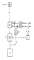
- a transmit signal according to frequency and modulation is generated in a transmit signal processing device SA and is supplied to the transmitter power output stage E.
- the transmitted signal amplified by the output stage passes through a directional coupler RK, the antenna lead L and an impedance matching device APG to the antenna A.
- a directional coupler RK couples out voltages U V and U R from the antenna feed which are proportional to the waves running from the output stage to the antenna or vice versa.
- the leading waves are formed by the transmission power emitted by the power output stage
- the returning waves are composed of the components reflected on the antenna and external signals received via the antenna, so that the voltage U V is proportional to the output power of the output stage and the voltage U R is proportional to the sum of reflected power and received power of external signals.
- a signal component is branched off from the transmission signal of the (variable) transmission frequency f o provided by the transmission signal processing unit and supplied to the output stage E and fed to a single-sideband generator ESB.
- a low frequency signal of constant frequency f z is also fed to the single sideband generator.
- the single-sideband generator outputs a single-sideband signal of the frequency f o + f z or f o - f at its output.
- the voltages U V and U R are frequency-converted with the single-sideband signal, and the low-frequency components at frequency f z are filtered out, amplified and converted into amplitude-proportional DC voltages V and R from the mixer output signals using low-pass filters TP.
- Foreign signals with a frequency distance to the transmission frequency f o which is significantly greater than the low frequency f z, lead to mixed products in the mixer output voltages at a frequency significantly higher than f z and can be easily suppressed by the low-pass filter.
- the forward and reverse signals V and R are then only proportional to the amplitudes of the forward and reverse waves at the transmission frequency f o and are not falsified by external radiation.
- a control signal generator G derives from the signals V and R a control signal T for setting the gain of the power output stage E. External signals on the antenna feed do not cause the control loop to react.
Landscapes
- Engineering & Computer Science (AREA)
- Power Engineering (AREA)
- Physics & Mathematics (AREA)
- Nonlinear Science (AREA)
- Computer Networks & Wireless Communication (AREA)
- Signal Processing (AREA)
- Transmitters (AREA)
Applications Claiming Priority (2)
| Application Number | Priority Date | Filing Date | Title |
|---|---|---|---|
| DE3821181 | 1988-06-23 | ||
| DE3821181A DE3821181A1 (de) | 1988-06-23 | 1988-06-23 | Leistungsregelanordnung |
Publications (3)
| Publication Number | Publication Date |
|---|---|
| EP0347569A2 true EP0347569A2 (fr) | 1989-12-27 |
| EP0347569A3 EP0347569A3 (en) | 1990-07-18 |
| EP0347569B1 EP0347569B1 (fr) | 1995-02-01 |
Family
ID=6357068
Family Applications (1)
| Application Number | Title | Priority Date | Filing Date |
|---|---|---|---|
| EP89108349A Expired - Lifetime EP0347569B1 (fr) | 1988-06-23 | 1989-05-10 | Dispositif de régulation de puissance |
Country Status (2)
| Country | Link |
|---|---|
| EP (1) | EP0347569B1 (fr) |
| DE (2) | DE3821181A1 (fr) |
Cited By (1)
| Publication number | Priority date | Publication date | Assignee | Title |
|---|---|---|---|---|
| EP1193884A3 (fr) * | 2000-09-28 | 2003-10-15 | Bundesr. Deutschland, vertr. d. d. Bundesministerium für Wirtschaft und Techn., vert. d. den Präs. der Physi.Tech. Bundesansta | Bus de secteur à sécurite intrinsèque |
Families Citing this family (3)
| Publication number | Priority date | Publication date | Assignee | Title |
|---|---|---|---|---|
| JP2669277B2 (ja) * | 1992-09-18 | 1997-10-27 | 株式会社日立製作所 | セラミックス焼結体の寿命予測法及び装置 |
| DE102006001687A1 (de) | 2005-04-01 | 2006-10-05 | Rohde & Schwarz Gmbh & Co. Kg | Leistungsregelvorrichtung |
| DE102006016761A1 (de) | 2006-04-10 | 2007-10-18 | Infineon Technologies Ag | Sendevorrichtung und Verfahren zum Übertragen eines Datensignals |
Family Cites Families (2)
| Publication number | Priority date | Publication date | Assignee | Title |
|---|---|---|---|---|
| DE2710752A1 (de) * | 1977-03-11 | 1978-09-14 | Rohde & Schwarz | Schaltung zum regeln der ausgangsleistung eines hochfrequenz-nachrichtensenders |
| DE3317358A1 (de) * | 1982-05-21 | 1983-11-24 | Licentia Patent-Verwaltungs-Gmbh, 6000 Frankfurt | Reflektometer |
-
1988
- 1988-06-23 DE DE3821181A patent/DE3821181A1/de not_active Withdrawn
-
1989
- 1989-05-10 DE DE58908956T patent/DE58908956D1/de not_active Expired - Fee Related
- 1989-05-10 EP EP89108349A patent/EP0347569B1/fr not_active Expired - Lifetime
Cited By (1)
| Publication number | Priority date | Publication date | Assignee | Title |
|---|---|---|---|---|
| EP1193884A3 (fr) * | 2000-09-28 | 2003-10-15 | Bundesr. Deutschland, vertr. d. d. Bundesministerium für Wirtschaft und Techn., vert. d. den Präs. der Physi.Tech. Bundesansta | Bus de secteur à sécurite intrinsèque |
Also Published As
| Publication number | Publication date |
|---|---|
| DE3821181A1 (de) | 1989-12-28 |
| DE58908956D1 (de) | 1995-03-16 |
| EP0347569B1 (fr) | 1995-02-01 |
| EP0347569A3 (en) | 1990-07-18 |
Similar Documents
| Publication | Publication Date | Title |
|---|---|---|
| EP0082491B1 (fr) | Circuit d'émission et de réception pour un dispositif d'identification automatique d'objets et/ou d'êtres vivants | |
| DE2755867C2 (de) | Frequenzumsetzeranordnung bei einem Sende-Empfangsgerät | |
| EP2101278A2 (fr) | Circuit de compensation pour une unité de lecteur RFID et unité de lecteur RFID | |
| EP0959569A1 (fr) | Méthode et appareille pour le couplage de signaux dans un càble haute ou moyenne tension | |
| DE2915069A1 (de) | Zeitabhaengig geregelter verstaerker fuer seitenabtast-sonar | |
| DE69112774T2 (de) | Gerät zum Empfangen und Senden von HF-Signalen. | |
| DE3147322A1 (de) | Hochfrequenz-sender, der frequenzmodulierte signale abstrahlt | |
| DE102015217695A1 (de) | Kommunikationsvorrichtung mit Antennen-Dämpfungskompensation | |
| DE3871604T2 (de) | Sender und senderempfaenger fuer ein kohaerentes optisches system. | |
| DE2811883C2 (de) | Sendeeinrichtung für eine Radaranlage mit zwei Sendeeinheiten | |
| DE69431699T2 (de) | Radioempfänger | |
| EP0347569A2 (fr) | Dispositif de régulation de puissance | |
| WO2000052838A1 (fr) | Emetteur a multiplexage en frequence et procede pour supprimer la diaphonie | |
| DE2322677A1 (de) | Asynchronimpulsempfaenger | |
| EP0401545B1 (fr) | Agencement de régulation de la puissance | |
| EP1275976A1 (fr) | Appareil pour tester la fonction d'un radar à ondes continues | |
| DE815356C (de) | Sprechanlage | |
| DE102012218730B4 (de) | Verstärkungsgrad-Messchaltung, Verstärkungsgrad-Messverfahren und Kommunikationsgerät | |
| DE69630621T2 (de) | Fernsteuereinrichtung für ein netzleitungsübertragungssystem | |
| DE817926C (de) | Frequenzmodulationsvorsatzgeraet fuer einen Rundfunkempfaenger | |
| DE3127670C2 (de) | Hörhilfe | |
| DE1070242B (de) | Anordnung zur Überwachung eines mehrstufigen, mit Frequenzumsetzung arbeitenden Sendeverstärkers | |
| EP1952178A1 (fr) | Instrument de mesure de distance et procédé de détermination d'une distance | |
| DD218242A1 (de) | Linearer optokoppler zur analogen messwertuebertragung | |
| WO2005112298A1 (fr) | Regulation de puissance dans des emetteurs haute frequence |
Legal Events
| Date | Code | Title | Description |
|---|---|---|---|
| PUAI | Public reference made under article 153(3) epc to a published international application that has entered the european phase |
Free format text: ORIGINAL CODE: 0009012 |
|
| AK | Designated contracting states |
Kind code of ref document: A2 Designated state(s): DE GB IT |
|
| RAP1 | Party data changed (applicant data changed or rights of an application transferred) |
Owner name: TELEFUNKEN SYSTEMTECHNIK GMBH |
|
| PUAL | Search report despatched |
Free format text: ORIGINAL CODE: 0009013 |
|
| RHK1 | Main classification (correction) |
Ipc: H03L 5/02 |
|
| AK | Designated contracting states |
Kind code of ref document: A3 Designated state(s): DE GB IT |
|
| 17P | Request for examination filed |
Effective date: 19901220 |
|
| RAP1 | Party data changed (applicant data changed or rights of an application transferred) |
Owner name: TELEFUNKEN SYSTEMTECHNIK AG |
|
| RAP1 | Party data changed (applicant data changed or rights of an application transferred) |
Owner name: DEUTSCHE AEROSPACE AKTIENGESELLSCHAFT |
|
| 17Q | First examination report despatched |
Effective date: 19930920 |
|
| GRAA | (expected) grant |
Free format text: ORIGINAL CODE: 0009210 |
|
| AK | Designated contracting states |
Kind code of ref document: B1 Designated state(s): DE GB IT |
|
| ITF | It: translation for a ep patent filed | ||
| RAP2 | Party data changed (patent owner data changed or rights of a patent transferred) |
Owner name: DAIMLER-BENZ AEROSPACE AKTIENGESELLSCHAFT |
|
| REF | Corresponds to: |
Ref document number: 58908956 Country of ref document: DE Date of ref document: 19950316 |
|
| GBT | Gb: translation of ep patent filed (gb section 77(6)(a)/1977) |
Effective date: 19950505 |
|
| PLBE | No opposition filed within time limit |
Free format text: ORIGINAL CODE: 0009261 |
|
| STAA | Information on the status of an ep patent application or granted ep patent |
Free format text: STATUS: NO OPPOSITION FILED WITHIN TIME LIMIT |
|
| 26N | No opposition filed | ||
| PGFP | Annual fee paid to national office [announced via postgrant information from national office to epo] |
Ref country code: GB Payment date: 20010412 Year of fee payment: 13 |
|
| PGFP | Annual fee paid to national office [announced via postgrant information from national office to epo] |
Ref country code: DE Payment date: 20010509 Year of fee payment: 13 |
|
| REG | Reference to a national code |
Ref country code: GB Ref legal event code: IF02 |
|
| PG25 | Lapsed in a contracting state [announced via postgrant information from national office to epo] |
Ref country code: GB Free format text: LAPSE BECAUSE OF NON-PAYMENT OF DUE FEES Effective date: 20020510 |
|
| PG25 | Lapsed in a contracting state [announced via postgrant information from national office to epo] |
Ref country code: DE Free format text: LAPSE BECAUSE OF NON-PAYMENT OF DUE FEES Effective date: 20021203 |
|
| GBPC | Gb: european patent ceased through non-payment of renewal fee |
Effective date: 20020510 |
|
| PG25 | Lapsed in a contracting state [announced via postgrant information from national office to epo] |
Ref country code: IT Free format text: LAPSE BECAUSE OF NON-PAYMENT OF DUE FEES;WARNING: LAPSES OF ITALIAN PATENTS WITH EFFECTIVE DATE BEFORE 2007 MAY HAVE OCCURRED AT ANY TIME BEFORE 2007. THE CORRECT EFFECTIVE DATE MAY BE DIFFERENT FROM THE ONE RECORDED. Effective date: 20050510 |