EP0346687A1 - Verfahren zur Störunterdrückung bei Ultraschall-Abstandsmessungen - Google Patents
Verfahren zur Störunterdrückung bei Ultraschall-Abstandsmessungen Download PDFInfo
- Publication number
- EP0346687A1 EP0346687A1 EP89109864A EP89109864A EP0346687A1 EP 0346687 A1 EP0346687 A1 EP 0346687A1 EP 89109864 A EP89109864 A EP 89109864A EP 89109864 A EP89109864 A EP 89109864A EP 0346687 A1 EP0346687 A1 EP 0346687A1
- Authority
- EP
- European Patent Office
- Prior art keywords
- digital values
- echo signal
- ultrasound
- stored
- digital
- Prior art date
- Legal status (The legal status is an assumption and is not a legal conclusion. Google has not performed a legal analysis and makes no representation as to the accuracy of the status listed.)
- Granted
Links
- 238000000034 method Methods 0.000 title claims abstract description 16
- 238000005259 measurement Methods 0.000 title claims abstract description 7
- 238000011156 evaluation Methods 0.000 claims abstract description 25
- 238000002604 ultrasonography Methods 0.000 claims abstract description 23
- 239000003999 initiator Substances 0.000 claims abstract description 16
- 238000005070 sampling Methods 0.000 claims description 6
- 238000012545 processing Methods 0.000 claims description 5
- 238000012935 Averaging Methods 0.000 claims description 3
- 230000005540 biological transmission Effects 0.000 claims description 3
- 230000007812 deficiency Effects 0.000 abstract 1
- 238000010586 diagram Methods 0.000 description 1
- 230000036039 immunity Effects 0.000 description 1
- 230000001629 suppression Effects 0.000 description 1
Images
Classifications
-
- G—PHYSICS
- G01—MEASURING; TESTING
- G01S—RADIO DIRECTION-FINDING; RADIO NAVIGATION; DETERMINING DISTANCE OR VELOCITY BY USE OF RADIO WAVES; LOCATING OR PRESENCE-DETECTING BY USE OF THE REFLECTION OR RERADIATION OF RADIO WAVES; ANALOGOUS ARRANGEMENTS USING OTHER WAVES
- G01S15/00—Systems using the reflection or reradiation of acoustic waves, e.g. sonar systems
- G01S15/02—Systems using the reflection or reradiation of acoustic waves, e.g. sonar systems using reflection of acoustic waves
- G01S15/06—Systems determining the position data of a target
- G01S15/08—Systems for measuring distance only
- G01S15/10—Systems for measuring distance only using transmission of interrupted, pulse-modulated waves
Definitions
- the invention relates to a method for suppressing stochastic interference signals in the distance measurement with a unit consisting of an ultrasound proximity initiator and a control and evaluation unit, the ultrasound proximity initiator repeatedly emitting ultrasound pulses of the same width and receiving the associated echo signal which in the control and evaluation unit are evaluated, stochastic deviations of the echo signal, which indicate interference signals, compared to the emitted ultrasound pulse, are taken into account in the distance determination.
- Interference suppression methods of the type mentioned are e.g. known from DE 34 28 773.
- the pulse width evaluation is described, in which incorrect pulses are separated out. False pulses are recognized by the fact that they are wider or narrower than the transmitted ultrasound pulses, which are all of the same width.
- This method can be used to limit false triggers, but the disadvantage here is that only a very rough evaluation is made as to whether the echo signal is subject to interference or not. In contrast, the information content given by the amplitude of the echo signal is not taken into account.
- the invention has for its object to provide an improved method for suppressing the stochastic interference signals occurring in distance measurements by means of an ultrasound proximity initiator in order to avoid incorrect messages and / or switching operations.
- an intermediate processing unit is connected between the output of the ultrasonic proximity initiator and the control and evaluation unit, consisting of a scanning device, an analog-digital converter, a processor, a data memory and a program memory , wherein the analog-digital converter is connected between the output and the processor, which is electrically connected to both the program memory, the data memory and the control and evaluation unit.
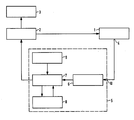
- the drawing shows the block diagram with the device for ultrasonic distance measurement.
- the device for ultrasound distance measurement consists of an ultrasound proximity initiator 1, a control and evaluation unit 2, a display unit 3 and an intermediate processing unit 5, which is connected between the ultrasound proximity initiator 1 and the control and evaluation unit 2.
- the intermediate processing unit 5 is composed of an analog-to-digital converter 6 with an integrated scanning device, a processor 7, a data memory 8 and a program memory 9.
- the analog-digital converter 6 is located at the input 10 of the intermediate processing unit 5 and is connected on the output side to the processor 7, the output of which is in turn connected to the control and evaluation unit 2.
- the data memory 8 and the program memory 9 are electrically connected to the processor 7. Due to the control by the control and evaluation unit 2, the ultrasound proximity initiator 1 cyclically emits ultrasound pulses of the same width and receives associated echo signals.
- the analog signal present at the output 4 of the ultrasound proximity initiator 1 is sampled from the moment in which the transmission of the ultrasound pulse has ended.
- the scanning takes place until the time at which the next ultrasound pulse begins to be transmitted.
- the sampling takes place at equal time intervals.
- the sampled analog values are digitized in the analog-digital converter 6 and forwarded to the processor 7. Via the processor 7, these digitized samples are mathematically / logically linked to the time-equivalent digital values that are stored in the data memory 8.
- the time intervals between the samples depend on the selected mathematical / logical connection type and on the components that carry out the connection. Leave for simple shortcuts intervals of less than 30 - 50 us reach.
- a program is stored in the program memory 9, which controls the link to be executed in the processor 7.
- the corresponding digital values are linked to one another by averaging, the digital values stored in the data memory 8 being able to be weighted differently from the last digital sampled values.
- the last digital sample value is, for example, 1 and the corresponding stored digital value is, for example, 3. If the weighting factor for the stored digital values is 4 and 1 for the last sampled values, a new value 2.6 results from this.
- the digital values determined in this way are stored in the data memory 8 instead of the stored digital values for corresponding times.
- the new digital values are forwarded from the processor 7 to the control and evaluation unit 2.
- the digital values are evaluated here, the object distance to be measured being determined, as is customary, from the time interval between the transmission of the ultrasound pulse and the reception of the associated echo signal.
- the known pulse width evaluation is carried out in order to recognize the echo signal.
- the amplitude of the digital values is also evaluated in the method according to the invention.
- a limit value is specified which is as high as possible but below the amplitude delivered for the echo signal. Only the pulses above the limit value are evaluated and pulses below the limit value, eg stochastic interference signals, are suppressed. In this way, the echo signal and thus the object distance can be determined with greater interference immunity.
- the following echo signal is used as the basis for the procedure described above.
- the determined distance value can be displayed on a display unit 3, which is connected to the control and evaluation unit 2. It is also possible to get one the control and display unit 2 downstream electronic switch to switch at a certain distance overshoot or undershoot.
Landscapes
- Physics & Mathematics (AREA)
- Engineering & Computer Science (AREA)
- Radar, Positioning & Navigation (AREA)
- Remote Sensing (AREA)
- Acoustics & Sound (AREA)
- Computer Networks & Wireless Communication (AREA)
- General Physics & Mathematics (AREA)
- Measurement Of Velocity Or Position Using Acoustic Or Ultrasonic Waves (AREA)
- Investigating Or Analyzing Materials By The Use Of Ultrasonic Waves (AREA)
- Length Measuring Devices Characterised By Use Of Acoustic Means (AREA)
- Transducers For Ultrasonic Waves (AREA)
Abstract
Description
- Die Erfindung bezieht sich auf ein Verfahren zur Unterdrükkung von stochastischen Störsignalen bei der Abstandsmessung mit einer aus einem Ultraschall-Näherungsinitiator und einer Steuer- und Auswerteeinheit bestehenden Einheit, wobei der Ultraschall-Näherungsinitiator wiederholt Ultraschall-Impulse gleicher Breite aussendet und dazugehörige Echosignal empfängt, die in der Steuer- und Auswerteeinheit ausgewertet werden, wobei stochastische, auf Störsignale hinweisende Abweichungen des Echosignals gegenüber dem ausgesendeten Ultraschall-Impuls in der Abstandsermittlung berücksichtigt werden.
- Verfahren zur Störunterdrückung der genannten Art sind z.B. aus der DE 34 28 773 bekannt. Hier wird die Pulsbreitenauswertung beschrieben, bei der Fehlimpulse ausgesondert werden. Fehlimpulse werden daran erkannt, daß sie breiter oder schmaler sind als die gesendeten Ultraschall-Impulse, die sämtlich gleich breit sind. Mit dieser Methode können zwar Fehlauslösungen eingeschränkt werden, doch besteht hierbei der Nachteil, daß nur sehr grob ausgewertet wird, ob das Echosignal störbehaftet ist oder nicht. Der durch die Amplitude des Echosignals gegebene Informationsgehalt bleibt dagegen unberücksichtigt.
- Der Erfindung liegt die Aufgabe zugrunde, ein verbessertes Verfahren zur Unterdrückung der bei Abstandsmessungen mittels eines Ultraschall-Näherungsinitiators auftretenden stochastischen Störsignale zu schaffen, um fehlerhafte Meldungen und/oder Schalthandlungen zu vermeiden.
- Dies wird auf einfache Weise bei einem Verfahren der obengenannten Art dadurch erreicht, daß das am Ausgang des Ultraschall-Näherungsinitiators anstehende, analoge Echosignal in Form eines Puls-Wellenbündels vor Zuführung zur Steuer- und Auswerteeinheit zwischenverarbeitet wird, indem das Echosignal zu bestimmten, für jedes Puls-Wellenbündel gleichen Zeitpunkten abgetastet wird und danach die abgetasteten Analogwerte in Digitalwerte umgewandelt werden und daß diese digitalen Abtastwerte dann mit den für äquivalente Zeitpunkte aus den vorherigen Echosignalen ermittelten und abgespeicherten Digitalwerten mathematisch/logisch zu neuen Digitalwerten verknüpft werden, wobei die sich zeitlich entsprechenden digitalen Abtastwerte und die gespeicherten Digitalwerte in gewünschter Höhe gewichtet werden und daß darauf die neuen Digitalwerte anstelle der zuletzt gespeicherten Digitalwerte abgespeichert werden und außerdem der Steuer- und Auswerteeinheit zur weiteren Auswertung hinsichtlich Amplitude und/oder Pulsbreite zugeleitet werden. Erfolgt die mathematisch/logische Verknüpfung der gewichteten, digitalen Abtastwerte mit den für das vorherige Puls-Wellenbündel abgespeicherten und gewichteten Digitalwerte durch Mittelwertbildung zu neuen Digitalwerten, so stellt dies eine besonders einfache, leicht zu realisierende Verknüpfung dar. Es ist vorteilhaft, wenn jedes Echosignal in zeitlich äquidistanten Abständen abgetastet wird, weil hierdurch die Abtastung zu gleichen Zeitpunkten jedes Puls-Wellenbündels mit geringem Aufwand erreicht wird.
- Die technischen Mittel zur Durchführung des obengenannten Verfahrens bestehen darin, daß zwischen dem Ausgang des Ultraschall-Näherungsinitiators und der Steuer- und Auswerteeinheit eine Zwischenverarbeitungseinheit geschaltet ist, bestehend aus einer Abtasteinrichtung, einem Analog-Digital-Wandler, einem Prozessor, einem Datenspeicher und einem Programmspeicher, wobei der Analog-Digital-Wandler zwischen den Ausgang und den Prozessor geschaltet ist, der sowohl mit dem Programmspeicher, dem Datenspeicher und der Steuer- und Auswerteeinheit elektrisch verbunden ist.
- Anhand der Zeichnung wird ein Ausführungsbeispiel gemäß der Erfindung beschrieben.
- Die Zeichnung zeigt das Blockschaltbild mit der Einrichtung zur Ultraschall-Abstandsmessung.
- Die Einrichtung zur Ultraschall-Abstandsmessung, besteht aus einem Ultraschall-Näherungsinitiator 1, einer Steuer- und Auswerteeinheit 2, einer Anzeigeeinheit 3 und einer Zwischenverarbeitungseinheit 5, die zwischen den Ultraschall-Näherungsinitiator 1 und die Steuer- und Auswerteeinheit 2 geschaltet ist. Die Zwischenverarbeitungseinheit 5 ist aus einem Analog-Digital-Wandler 6 mit integrierter Abtasteinrichtung, einem Prozessor 7, einem Datenspeicher 8 und einem Programmspeicher 9 zusammengesetzt. Der Analog-Digital-Wandler 6 liegt am Eingang 10 der Zwischenverarbeitungseinheit 5 und ist ausgangsseitig mit dem Prozessor 7 verbunden, dessen Ausgang wiederum an die Steuer- und Auswerteeinheit 2 angeschlossen ist. Der Datenspeicher 8 und der Programmspeicher 9 stehen mit dem Prozessor 7 elektrisch in Verbindung. Aufgrund der Steuerung durch die Steuer- und Auswerteeinheit 2 sendet der Ultraschall-Näherungsinitiator 1 zyklisch Ultraschall-Impule gleicher Breite aus und empfängt dazugehörige Echosignale. Das am Ausgang 4 des Ultraschall-Näherungsinitiators 1 anstehende analoge Signal wird von dem Moment ab abgetastet, in dem die Aussendung des Ultraschall-Impulses beendet ist. Die Abtastung erfolgt bis zum Zeitpunkt, in dem die Aussendung des nächsten Ultraschall-Impulses beginnt. Die Abtastung erfolgt in gleichen Zeitabständen. Die abgetasteten Analogwerte werden im Analog-Digital-Wandler 6 digitalisiert und an den Prozessor 7 weitergeleitet. Über den Prozessor 7 werden diese digitalisierten Abtastwerte mit den zeitäquivalenten Digitalwerten, die im Datenspeicher 8 gespeichert sind, mathematisch/logisch verknüpft. Die Zeitabstände zwischen den Abtastungen sind abhängig von der gewählten mathematisch/logischen Verknüpfungsart und von den die Verknüpfung ausführenden Bauelementen. Für einfache Verknüpfungen lassen sich Zeitabstände unter z.B. 30 - 50 us erreichen. In dem Programmspeicher 9 ist ein Programm abgelegt, welches die im Prozessor 7 auszuführende Verknüpfung steuert. Im einfachsten Fall werden die entsprechenden Digitalwerte durch eine Mittelwertbildung miteinander verknüpft, wobei die im Datenspeicher 8 gespeicherten Digitalwerte verschieden von den letzten digitalen Abtastwerten gewichtet werden können. Hierzu sei folgendes Beispiel gegeben: Der letzte digitale Abtastwert beträgt z.B. 1 und der entsprechende abgespeicherte Digitalwert z.B. 3. Beträgt dann z.B. der Wichtungsfaktor für die abgespeicherten Digitalwerte 4 und für die zuletzt abgetasteten Werte 1, so ergibt sich hieraus durch Mittelwertbildung ein neuer Wert 2.6. Die so ermittelten Digitalwerte werden anstelle der abgespeicherten Digitalwerte für entsprechende Zeitpunkte im Datenspeicher 8 abgelegt. Außerdem werden die neuen Digitalwerte von dem Prozessor 7 aus an die Steuer- und Auswerteeinheit 2 weitergeleitet. Hier werden die Digitalwerte ausgewertet, wobei der zu messende Objektabstand wie in üblicher Weise aus dem zeitlichen Abstand zwischen der Aussendung des Ultraschallimpulses und dem Empfang des zugehörigen Echosignals ermittelt wird. Zum Erkennen des Echosignals wird die bekannte Pulsbreitenauswertung vorgenommen. Darüber hinaus wird in dem erfindungsgemäßen Verfahren aber auch die Amplitude der Digitalwerte ausgewertet. Hierbei wird ein Grenzwert vorgegeben, der möglichst hoch aber unterhalb der für das Echosignal gelieferten Amplitude liegt. Es werden nur die oberhalb des Grenzwertes liegenden Impulse ausgewertet und unterhalb des Grenzwertes liegende Impulse, z.B. stochastische Störsignale, unterdrückt. Auf diese Weise läßt sich das Echosignal und damit der Objektabstand mit höhrer Störsicherheit ermitteln.
- Zur Ermittlung des folgenden Abstandswertes wird unter Zugrundelegung des folgenden Echosignals in der zuvor beschriebenen Weise verfahren. Der ermittelte Abstandswert kann auf einer Anzeigeeinheit 3, die an der Steuer- und Auswerteeinheit 2 angeschlossen ist, angezeigt werden. Es ist auch möglich, einen der Steuer- und Anzeigeeinheit 2 nachgeschalteten elektronischen Schalter bei einer bestimmten Abstandsüber- oder -unterschreitung schalten zu lassen.
Claims (5)
Priority Applications (1)
| Application Number | Priority Date | Filing Date | Title |
|---|---|---|---|
| AT89109864T ATE92639T1 (de) | 1988-06-13 | 1989-05-31 | Verfahren zur stoerunterdrueckung bei ultraschall- abstandsmessungen. |
Applications Claiming Priority (2)
| Application Number | Priority Date | Filing Date | Title |
|---|---|---|---|
| DE3820103 | 1988-06-13 | ||
| DE3820103 | 1988-06-13 |
Publications (2)
| Publication Number | Publication Date |
|---|---|
| EP0346687A1 true EP0346687A1 (de) | 1989-12-20 |
| EP0346687B1 EP0346687B1 (de) | 1993-08-04 |
Family
ID=6356458
Family Applications (1)
| Application Number | Title | Priority Date | Filing Date |
|---|---|---|---|
| EP89109864A Expired - Lifetime EP0346687B1 (de) | 1988-06-13 | 1989-05-31 | Verfahren zur Störunterdrückung bei Ultraschall-Abstandsmessungen |
Country Status (6)
| Country | Link |
|---|---|
| US (1) | US5036477A (de) |
| EP (1) | EP0346687B1 (de) |
| JP (1) | JPH0232285A (de) |
| AT (1) | ATE92639T1 (de) |
| DE (1) | DE58905114D1 (de) |
| ES (1) | ES2041892T3 (de) |
Cited By (3)
| Publication number | Priority date | Publication date | Assignee | Title |
|---|---|---|---|---|
| EP0369050B1 (de) * | 1988-11-15 | 1993-08-11 | Siemens Aktiengesellschaft | Verfahren zur Unterdrückung von Störsignalen beim Betrieb von Ultraschall-Näherungsinitiatoren |
| US5587969A (en) * | 1993-03-16 | 1996-12-24 | Siemens Aktiengesellschaft | Process for the recognition and separation of useful and interfering echoes in the received signals of distance sensors which operate in accordance with the pulse-echo principle |
| DE102007043501A1 (de) * | 2007-09-12 | 2009-03-19 | Valeo Schalter Und Sensoren Gmbh | Verfahren und Anordnung zur Auswertung von Ultraschallsignalen |
Families Citing this family (8)
| Publication number | Priority date | Publication date | Assignee | Title |
|---|---|---|---|---|
| JPH04188181A (ja) * | 1990-11-22 | 1992-07-06 | Nissan Motor Co Ltd | 車両用経路検索装置 |
| DE4106892A1 (de) * | 1991-03-05 | 1992-09-10 | Zeiss Carl Fa | Verfahren und vorrichtung zum messen von entfernungen |
| US5339259A (en) * | 1992-07-10 | 1994-08-16 | Northrop Grumman Corporation | High speed high resolution ultrasonic position and orientation tracker |
| US5453932A (en) * | 1994-01-12 | 1995-09-26 | Advanced Grade Technology, Inc. | Device and method for detecting and elimination of spurious ultrasonic ranging echoes |
| EP1069438A1 (de) * | 1999-07-15 | 2001-01-17 | Endress + Hauser Gmbh + Co. | Verfahren und Vorrichtung zur hochgenauen Bestimmung des Füllstandes eines Füllguts in einem Behälter |
| US6805132B2 (en) * | 2002-08-06 | 2004-10-19 | Scimed Life Systems, Inc. | Performing ultrasound ranging in the presence of ultrasound interference |
| DE10343350A1 (de) * | 2003-09-12 | 2005-04-21 | Siemens Ag | Verfahren zur Steuerung eines elektronischen Überstromauslösers für Niederspannungs-Leistungsschalter |
| EP2372318B1 (de) * | 2010-03-26 | 2020-03-18 | VEGA Grieshaber KG | Störechospeicherung bei Behälterrauschen |
Citations (4)
| Publication number | Priority date | Publication date | Assignee | Title |
|---|---|---|---|---|
| GB2129935A (en) * | 1982-03-30 | 1984-05-23 | Marconi Co Ltd | An adaptive filter |
| FR2568687A1 (fr) * | 1984-08-03 | 1986-02-07 | Siemens Ag | Declencheur de proximite a ultra-sons |
| EP0174090A2 (de) * | 1984-08-31 | 1986-03-12 | United Kingdom Atomic Energy Authority | Diskriminierung von elektrischen Signalen |
| US4596144A (en) * | 1984-09-27 | 1986-06-24 | Canadian Corporate Management Co., Ltd. | Acoustic ranging system |
Family Cites Families (10)
| Publication number | Priority date | Publication date | Assignee | Title |
|---|---|---|---|---|
| US4243935A (en) * | 1979-05-18 | 1981-01-06 | The United States Of America As Represented By The Secretary Of The Navy | Adaptive detector |
| FR2478320A1 (fr) * | 1980-03-17 | 1981-09-18 | Telediffusion Fse | Dispositif d'acquisition et de moyennage des echantillons d'un signal periodique bruite |
| JPS58121941A (ja) * | 1982-01-13 | 1983-07-20 | テルモ株式会社 | 超音波診断装置 |
| US4573133A (en) * | 1983-04-19 | 1986-02-25 | Rockwell International Corporation | Signal processor for compensating detector non-uniformities |
| JPS6064282A (ja) * | 1983-09-19 | 1985-04-12 | Nissan Motor Co Ltd | 超音波式距離測定装置 |
| IT1208769B (it) * | 1983-10-12 | 1989-07-10 | Cselt Centro Studi Lab Telecom | Teristiche varianti nel tempo procedimento e dispositivo per la cancellazione numerica dell eco generato in collegamenti con carat |
| US4684989A (en) * | 1986-02-07 | 1987-08-04 | Rca Corporation | Signal background noise detector |
| GB2197766B (en) * | 1986-11-17 | 1990-07-25 | Sony Corp | Two-dimensional finite impulse response filter arrangements |
| US4800540A (en) * | 1986-12-04 | 1989-01-24 | The United States Of America As Represented By The United States Department Of Energy | Discriminating ultrasonic proximity detection system |
| US4933914A (en) * | 1987-01-15 | 1990-06-12 | Hughes Aircraft Company | Channel adaptive active sonar |
-
1989
- 1989-05-31 ES ES198989109864T patent/ES2041892T3/es not_active Expired - Lifetime
- 1989-05-31 AT AT89109864T patent/ATE92639T1/de not_active IP Right Cessation
- 1989-05-31 DE DE8989109864T patent/DE58905114D1/de not_active Expired - Fee Related
- 1989-05-31 EP EP89109864A patent/EP0346687B1/de not_active Expired - Lifetime
- 1989-06-07 JP JP1145032A patent/JPH0232285A/ja active Pending
- 1989-06-13 US US07/365,415 patent/US5036477A/en not_active Expired - Fee Related
Patent Citations (5)
| Publication number | Priority date | Publication date | Assignee | Title |
|---|---|---|---|---|
| GB2129935A (en) * | 1982-03-30 | 1984-05-23 | Marconi Co Ltd | An adaptive filter |
| FR2568687A1 (fr) * | 1984-08-03 | 1986-02-07 | Siemens Ag | Declencheur de proximite a ultra-sons |
| EP0174090A2 (de) * | 1984-08-31 | 1986-03-12 | United Kingdom Atomic Energy Authority | Diskriminierung von elektrischen Signalen |
| US4596144A (en) * | 1984-09-27 | 1986-06-24 | Canadian Corporate Management Co., Ltd. | Acoustic ranging system |
| US4596144B1 (en) * | 1984-09-27 | 1995-10-10 | Federal Ind Ind Group Inc | Acoustic ranging system |
Non-Patent Citations (1)
| Title |
|---|
| ULTRASONICS, Band 11, Nr. 4, Juli 1973, Seiten 165-173, Guilford, Surrey, GB; S. LEES et al.: "DONAR: a computer processing system to extend ultrasonic pulse-echo testing" * |
Cited By (3)
| Publication number | Priority date | Publication date | Assignee | Title |
|---|---|---|---|---|
| EP0369050B1 (de) * | 1988-11-15 | 1993-08-11 | Siemens Aktiengesellschaft | Verfahren zur Unterdrückung von Störsignalen beim Betrieb von Ultraschall-Näherungsinitiatoren |
| US5587969A (en) * | 1993-03-16 | 1996-12-24 | Siemens Aktiengesellschaft | Process for the recognition and separation of useful and interfering echoes in the received signals of distance sensors which operate in accordance with the pulse-echo principle |
| DE102007043501A1 (de) * | 2007-09-12 | 2009-03-19 | Valeo Schalter Und Sensoren Gmbh | Verfahren und Anordnung zur Auswertung von Ultraschallsignalen |
Also Published As
| Publication number | Publication date |
|---|---|
| JPH0232285A (ja) | 1990-02-02 |
| EP0346687B1 (de) | 1993-08-04 |
| DE58905114D1 (de) | 1993-09-09 |
| US5036477A (en) | 1991-07-30 |
| ES2041892T3 (es) | 1993-12-01 |
| ATE92639T1 (de) | 1993-08-15 |
Similar Documents
| Publication | Publication Date | Title |
|---|---|---|
| DE69813443T2 (de) | Impulsgeneratorschaltung für Zeitbereichsreflektometer | |
| EP0346687B1 (de) | Verfahren zur Störunterdrückung bei Ultraschall-Abstandsmessungen | |
| EP0171579B1 (de) | Anordnung zur seriellen Übertragung der Messwerte wenigstens eines Messwertwandlers | |
| DE1623537A1 (de) | Vorrichtung zum Messen von Abstaenden mittels Ultraschall | |
| DE2649075B2 (de) | Verfahren und Anordnung zur Messung des Füllstandes in einem Behälter bzw. der Schüttguthöhe auf einem Lagerplatz | |
| DE3533479C2 (de) | ||
| DE2643383A1 (de) | Schaltanordnung fuer ein ultraschall- impulsechoverfahren zur messung der dicke bzw. schallgeschwindigkeit in pruefstuecken | |
| DE2925522A1 (de) | Verfahren und schaltungsanordnung zur digitalen messung analoger messgroessen | |
| EP0369050B1 (de) | Verfahren zur Unterdrückung von Störsignalen beim Betrieb von Ultraschall-Näherungsinitiatoren | |
| DE2414007A1 (de) | Verfahren zum feststellen von objekten und anordnung zur durchfuehrung dieses verfahrens | |
| EP0218161B1 (de) | Verfahren zur Analyse und Synthese von binären Zeichen | |
| DE2548799B2 (de) | Verfahren und vorrichtung zum messen der periodendauer bzw. frequenz eines signals | |
| EP0646249B1 (de) | Verfahren zum ermitteln von anomalien einer zu untersuchenden leitung | |
| DE2331150B2 (de) | Frequenzanalysator | |
| DE3032467C2 (de) | ||
| DE3689556T2 (de) | Gerät und Verfahren zur Umwandlung einer Spannung in einen digitalen Zählwert. | |
| DE3409748A1 (de) | Messvorrichtung mit digitaler anzeige | |
| DE2160327B2 (de) | Vorrichtung zur analog-digitalumsetzung von mittels wandlern gewonnenen analogsignalen | |
| DE2244677B1 (de) | Anordnung zum elektrischen messen mechanischer groessen | |
| DE2601150C3 (de) | Verfahren und Schaltungsanordnung zur Bildung von Signalen für die Stillstandskontrolle einer elektromagnetischen Präzisions- und Feinwaage | |
| DE2547746A1 (de) | Vorrichtung mit einer messwertgeber-einheit zur erzeugung einer folge von spannungswerten und einer mittelwertbildungs-einheit | |
| EP4135223B1 (de) | Verfahren zur erhöhung einer qualität von abgetasteten empfangssignalen und messgerät zur zeitbereichsreflektometrie | |
| EP3572768A1 (de) | Optischer sensor und verfahren zum betrieb eines optischen sensors | |
| DE2321018A1 (de) | Verfahren und vorrichtung zur messung der entfernung zwischen zwei messpunkten durch laufzeitmessung von schallimpulsen | |
| DE3611683A1 (de) | Digitales messverfahren zur anzeige von messwerten auf einem display |
Legal Events
| Date | Code | Title | Description |
|---|---|---|---|
| PUAI | Public reference made under article 153(3) epc to a published international application that has entered the european phase |
Free format text: ORIGINAL CODE: 0009012 |
|
| AK | Designated contracting states |
Kind code of ref document: A1 Designated state(s): AT CH DE ES FR GB IT LI |
|
| 17P | Request for examination filed |
Effective date: 19900126 |
|
| 17Q | First examination report despatched |
Effective date: 19920806 |
|
| GRAA | (expected) grant |
Free format text: ORIGINAL CODE: 0009210 |
|
| AK | Designated contracting states |
Kind code of ref document: B1 Designated state(s): AT CH DE ES FR GB IT LI |
|
| REF | Corresponds to: |
Ref document number: 92639 Country of ref document: AT Date of ref document: 19930815 Kind code of ref document: T |
|
| REF | Corresponds to: |
Ref document number: 58905114 Country of ref document: DE Date of ref document: 19930909 |
|
| ITF | It: translation for a ep patent filed | ||
| ET | Fr: translation filed | ||
| GBT | Gb: translation of ep patent filed (gb section 77(6)(a)/1977) |
Effective date: 19931019 |
|
| REG | Reference to a national code |
Ref country code: ES Ref legal event code: FG2A Ref document number: 2041892 Country of ref document: ES Kind code of ref document: T3 |
|
| PLBE | No opposition filed within time limit |
Free format text: ORIGINAL CODE: 0009261 |
|
| STAA | Information on the status of an ep patent application or granted ep patent |
Free format text: STATUS: NO OPPOSITION FILED WITHIN TIME LIMIT |
|
| 26N | No opposition filed | ||
| PGFP | Annual fee paid to national office [announced via postgrant information from national office to epo] |
Ref country code: AT Payment date: 19950421 Year of fee payment: 7 |
|
| PGFP | Annual fee paid to national office [announced via postgrant information from national office to epo] |
Ref country code: ES Payment date: 19950427 Year of fee payment: 7 |
|
| PG25 | Lapsed in a contracting state [announced via postgrant information from national office to epo] |
Ref country code: AT Effective date: 19960531 |
|
| PG25 | Lapsed in a contracting state [announced via postgrant information from national office to epo] |
Ref country code: ES Free format text: LAPSE BECAUSE OF NON-PAYMENT OF DUE FEES Effective date: 19960601 |
|
| PGFP | Annual fee paid to national office [announced via postgrant information from national office to epo] |
Ref country code: CH Payment date: 19960821 Year of fee payment: 8 |
|
| PG25 | Lapsed in a contracting state [announced via postgrant information from national office to epo] |
Ref country code: LI Free format text: LAPSE BECAUSE OF NON-PAYMENT OF DUE FEES Effective date: 19970531 Ref country code: CH Free format text: LAPSE BECAUSE OF NON-PAYMENT OF DUE FEES Effective date: 19970531 |
|
| REG | Reference to a national code |
Ref country code: CH Ref legal event code: PL |
|
| PGFP | Annual fee paid to national office [announced via postgrant information from national office to epo] |
Ref country code: GB Payment date: 19990510 Year of fee payment: 11 |
|
| REG | Reference to a national code |
Ref country code: ES Ref legal event code: FD2A Effective date: 19990405 |
|
| PGFP | Annual fee paid to national office [announced via postgrant information from national office to epo] |
Ref country code: FR Payment date: 19990520 Year of fee payment: 11 |
|
| PGFP | Annual fee paid to national office [announced via postgrant information from national office to epo] |
Ref country code: DE Payment date: 19990720 Year of fee payment: 11 |
|
| PG25 | Lapsed in a contracting state [announced via postgrant information from national office to epo] |
Ref country code: GB Free format text: LAPSE BECAUSE OF NON-PAYMENT OF DUE FEES Effective date: 20000531 |
|
| GBPC | Gb: european patent ceased through non-payment of renewal fee |
Effective date: 20000531 |
|
| PG25 | Lapsed in a contracting state [announced via postgrant information from national office to epo] |
Ref country code: FR Free format text: LAPSE BECAUSE OF NON-PAYMENT OF DUE FEES Effective date: 20010131 |
|
| PG25 | Lapsed in a contracting state [announced via postgrant information from national office to epo] |
Ref country code: DE Free format text: LAPSE BECAUSE OF NON-PAYMENT OF DUE FEES Effective date: 20010301 |
|
| REG | Reference to a national code |
Ref country code: FR Ref legal event code: ST |
|
| PG25 | Lapsed in a contracting state [announced via postgrant information from national office to epo] |
Ref country code: IT Free format text: LAPSE BECAUSE OF NON-PAYMENT OF DUE FEES;WARNING: LAPSES OF ITALIAN PATENTS WITH EFFECTIVE DATE BEFORE 2007 MAY HAVE OCCURRED AT ANY TIME BEFORE 2007. THE CORRECT EFFECTIVE DATE MAY BE DIFFERENT FROM THE ONE RECORDED. Effective date: 20050531 |