EP0346548A1 - Behälterleerzustandsdetektor - Google Patents
Behälterleerzustandsdetektor Download PDFInfo
- Publication number
- EP0346548A1 EP0346548A1 EP19880311343 EP88311343A EP0346548A1 EP 0346548 A1 EP0346548 A1 EP 0346548A1 EP 19880311343 EP19880311343 EP 19880311343 EP 88311343 A EP88311343 A EP 88311343A EP 0346548 A1 EP0346548 A1 EP 0346548A1
- Authority
- EP
- European Patent Office
- Prior art keywords
- tubing
- light
- tube
- groove
- sensor
- Prior art date
- Legal status (The legal status is an assumption and is not a legal conclusion. Google has not performed a legal analysis and makes no representation as to the accuracy of the status listed.)
- Granted
Links
Images


Classifications
-
- A—HUMAN NECESSITIES
- A61—MEDICAL OR VETERINARY SCIENCE; HYGIENE
- A61M—DEVICES FOR INTRODUCING MEDIA INTO, OR ONTO, THE BODY; DEVICES FOR TRANSDUCING BODY MEDIA OR FOR TAKING MEDIA FROM THE BODY; DEVICES FOR PRODUCING OR ENDING SLEEP OR STUPOR
- A61M5/00—Devices for bringing media into the body in a subcutaneous, intra-vascular or intramuscular way; Accessories therefor, e.g. filling or cleaning devices, arm-rests
- A61M5/36—Devices for bringing media into the body in a subcutaneous, intra-vascular or intramuscular way; Accessories therefor, e.g. filling or cleaning devices, arm-rests with means for eliminating or preventing injection or infusion of air into body
- A61M5/365—Air detectors
-
- A—HUMAN NECESSITIES
- A61—MEDICAL OR VETERINARY SCIENCE; HYGIENE
- A61M—DEVICES FOR INTRODUCING MEDIA INTO, OR ONTO, THE BODY; DEVICES FOR TRANSDUCING BODY MEDIA OR FOR TAKING MEDIA FROM THE BODY; DEVICES FOR PRODUCING OR ENDING SLEEP OR STUPOR
- A61M2205/00—General characteristics of the apparatus
- A61M2205/14—Detection of the presence or absence of a tube, a connector or a container in an apparatus
-
- A—HUMAN NECESSITIES
- A61—MEDICAL OR VETERINARY SCIENCE; HYGIENE
- A61M—DEVICES FOR INTRODUCING MEDIA INTO, OR ONTO, THE BODY; DEVICES FOR TRANSDUCING BODY MEDIA OR FOR TAKING MEDIA FROM THE BODY; DEVICES FOR PRODUCING OR ENDING SLEEP OR STUPOR
- A61M2205/00—General characteristics of the apparatus
- A61M2205/60—General characteristics of the apparatus with identification means
- A61M2205/6063—Optical identification systems
-
- Y—GENERAL TAGGING OF NEW TECHNOLOGICAL DEVELOPMENTS; GENERAL TAGGING OF CROSS-SECTIONAL TECHNOLOGIES SPANNING OVER SEVERAL SECTIONS OF THE IPC; TECHNICAL SUBJECTS COVERED BY FORMER USPC CROSS-REFERENCE ART COLLECTIONS [XRACs] AND DIGESTS
- Y10—TECHNICAL SUBJECTS COVERED BY FORMER USPC
- Y10S—TECHNICAL SUBJECTS COVERED BY FORMER USPC CROSS-REFERENCE ART COLLECTIONS [XRACs] AND DIGESTS
- Y10S128/00—Surgery
- Y10S128/13—Infusion monitoring
Definitions
- the present invention relates generally to a system for detecting air in a fluid line, and more particularly to a clamp-on detector apparatus for detecting air in the fluid line between a medication infusion reservoir such as an IV bottle or bag and an IV injection set or a medication infusion pump.
- medication may be delivered through a conventional IV system using a drip chamber with the injection being made into various IV tubes and the associated paraphernalia, with drop counters being used to meter the amount of fluid delivered.
- medication infusion pumps may be used to administer drugs to a patient in small, precisely metered doses at frequent intervals or, alternatively, in the case of some devices, at a low but essentially continuous rate. Infusion pump therapy is electronically controlled to deliver precise, metered doses at exactly determined intervals.
- An essential function of a medication infusion system is to avoid the infusion of fluid containing air bubbles. While a small amount of air may be contained in the fluid to be infused in very small air bubbles, larger air bubbles present a rear danger to the patient if infused. Although steps may be taken to monitor the fluid line downstream before it reaches the patient to ensure that substantially no air bubbles remain in the fluid which is to be infused, it is also essential to minimise the possibility of air bubbles being contained in fluid near the reservoir end of the infusion apparatus. The detection of air bubbles in all fluids which are to be infused is therefore a critical design requirement.
- the Hyman detector represents an improvement on manual air-in-line detectors, it sacrifices simplicity for its automatic operation, requiring five sets of optical detectors to perform its function. Not only is the Hyman device fairly complex, but it is necessarily relatively larger and more expensive to manufacture than would be desirable. As may be seen from the Hyman reference, the device is a built-in detector rather than an accessory detector, and is used (in the preferred embodiment) downstream of a pump. Due to its size, it is not readily usable as a standalone device, or as an empty container detector.
- the system of the present invention should be simple and easy to use, and should clamp onto a fluid line immediately downstream from the fluid reservoir or container.
- the empty container detection system of the present invention should be capable of immediately, accurately, and effectively detecting air in the fluid line regardless of whether the fluid being infused is opaque or transparent.
- the system should be fully automatic, not requiring any setup or intervention by an operator except clipping the device onto a line and plugging it in to the main pump unit or other controller.
- One such feature is the ability to detect air bubbles whether the flow rate of the fluid in the line is fast or slow.
- the system should also be accurate, presenting a high degree of resistance to false alarms. Since the detector of the system is to clip onto the fluid line, it should be small and light in size.
- the system of the present invention should employ a minimum number of parts, all of which should be of inexpensive construction, while yet affording the system the high degree of accuracy which must be retained.
- the system of the present invention should be able to compete economically with known system, and must provide an ease of use rivalling the best known systems.
- the system should accomplish all these objects in a manner which will retain and enhance all of the advantages of reliability, durability, and safety of operation, and overcome the limitations of the background art without incurring any relative disadvantage.
- a device for detecting the presence of air in hollow cylindrical tubing characterised by: a housing including a recessed groove for receiving a portion of the tubing; a light source located on one side of the groove, light from the light source being directed onto the tubing when the tubing is located in the groove; first detecting means for detecting the presence of light passing across the groove; and second detecting means for detecting light from the light source which enters the tubing located in the groove and is reflected off the inside of the tubing and directed onto the second detecting means.
- the first detecting means is a tube/no tube light sensor located in the housing on the other side of the groove from the light source, the tube/no tube light sensor receiving light from the light source when tubing is not located in the groove, the tube/no tube light sensor receiving substantially no light from the light source when tubing is located in the groove; and the second detecting means is a liquid-in-tube light sensor located in the housing, light from the light source which enters tubing located in the groove being reflected off the inside of the tubing and directed onto the liquid-in-tube light sensor when air is contained in the tubing, while substantially no light entering tubing located in the groove is reflected off the inside of the tubing and onto the liquid-in-tube light sensor when fluid is contained in the tubing, any light entering the tubing instead entering the fluid contained in the tubing.
- the device may also include an operating characteristic light sensor for monitoring and for producing an output signal indicative of the light produced by the light source, the operating characteristic light sensor preferably monitoring the light source to ensure that the light source is operating properly, and the system preferably additionally comprising means for providing an alarm if the light source is substantially inoperative.
- the device preferably includes means for monitoring the output signal from the operating characteristic light sensor, the monitoring means being arranged to measure the relative amounts of light detected by the tube/no tube sensor and the liquid-in-tube sensor when the level of light output from the light source is at a preselected level, which is preferably below the maximum level of light generated by the light source, and occurs when the level of light generated by the light source has fallen from a higher level to the preselected level.
- the recessed groove is essentially V-shaped
- the light source generates infrared (IR) light
- the tube/no tube light sensor and the liquid-in-tube light sensor sense IR light
- a V-shaped filter is located in the groove, the filter allowing only (IR) light to pass, the filter optionally being a polysulphone filter.
- the V-shaped filter is so geometrically arranged and configured as to allow the device to work identically for two different predetermined sizes of tubing optionally by the outer diameters of the two different predetermined sizes of tubing generally coinciding at the point at which light would enter the tubing from the filter and at the point at which light would leave tubing containing air and enter the filter on its path to the liquid-in-tube light sensor, and the inner diameters of the two different predetermined sizes of tubing being relatively located so as to reflect light off their inner walls at the same critical angle to direct the light onto the liquid-in-tube light sensor.
- the device preferably includes means for retaining tubing in the groove optionally comprising a clamping arm pivotally mounted on the housing, the clamping arm including a clamping segment located over the groove; and means for biasing the clamping segment located over the groove and means for biasing the clamping segment towards the recessed groove, the biasing means optionally comprising a spring.
- the clamping arm also includes a grip portion at the end opposite the clamping segment for opening the clamping arm to allow tubing to be installed into or removed from the groove.
- the device may include first alarm means for generating an alarm signal when the tube/no tube light sensor receives substantial light from the light source to indicate that tubing is not located in the groove, and second alarm means for generating an alarm signal when the liquid-in-tube sensor receives substantial light from the inside of the tubing.
- There may also be means for identifying the device to a main pump unit to which the device is connected, the identifying means optionally comprising a preselected resistance which may be sensed by the main pump unit to identify the device.
- the invention also extends to a method for detecting the presence of air in hollow cylindrical tubing characterised by directing light from a light source located in a housing to one side of a recessed groove in the housing, in which groove the tubing may be located; detecting whether or not tubing is properly located in the groove with a tube/no tube light sensor located in the housing on the other side of the groove from the light source, the tube/no tube light sensor receiving light from the light source when tubing is not located in the groove the tube/no tube light sensor receiving substantially no light from the light source when tubing is located in the recessed groove; and detecting whether or not air is contained in the tubing with a liquid-in-tube light sensor located in the housing, light from the light source which enters tubing located in the groove being reflected off the inside of the tubing and directed onto the liquid-in-tube light sensor when air is contained in the tubing while substantially no light entering tubing located in the groove is reflected off the inside of the tubing and onto the liquid-in-tube light sensor when fluid
- a clamp-on empty container detector device is used to detect the presence of air bubbles in a segment of tubing around which the device is clamped.
- the device uses a light-emitting diode (LED) which is periodically triggered to produce a burst of light at a desired sampling rate determined by the frequency of the triggering signal. If the tubing is empty of fluid or an air bubble is passing through it, the light is reflected at the inner diameter of the tubing and directed onto a liquid-in-tube sensor. If the liquid-in-tube sensor detects light, the signal is indicative of air in the tubing, and an alarm will be given.
- LED light-emitting diode
- the light will pass through the tubing without being reflected toward the liquid-in-tube sensor, in which case the light will not be directed onto the liquid-in-tube sensor. Rather, the light will continue in a path through the transparent liquid and through the opposite side of the tubing. Since the liquid-in-tube sensor is not located in line on the opposite side of the tubing, it will not detect the light. This is an indication that there is liquid in the tube.
- the light will pass through the tubing without being reflected, and again the light will not be directed onto the liquid-in-tube sensor. The light will continue in a path into the opaque liquid, and will be absorbed. Since the liquid-in-tube sensor does not detect the light, an indication is made that there is liquid in the tubing.
- the device of the present invention is therefore able to discriminate between air and liquid, regardless of whether the liquid is transparent or opaque.
- the inherent design of the present invention requires only a single light source and light sensor.
- an additional sensor is used to compensate for LED performance degradation caused by temperature and ageing of the LED. This sensor may also be used to verify that the light source (the LED) is in fact operating properly and is emitting light. Another additional sensor is used to verify that the tubing is properly situated in the device. By using these additional sensors, the proper operation of the system is ensured.
- the packaging of the system of the present invention is designed to be as size-efficient and easy-to-use as possible.
- the system is packaged in a clamp which may be clipped on to the supply tubing near the fluid reservoir.
- the system of the preferred embodiment is geometrically designed to work on either of two sizes of tubing, both of which are commonly used in medication infusion applications.
- the detector may easily be clamped onto the tubing using only one hand, and is lightweight to allow the device to be supported by the tubing thereby not requiring additional support apparatus.
- the device in the preferred embodiment is designed to be used with a medication infusion pump, and may be plugged into the main pump unit. Accordingly, the empty container detector of the present invention may be driven by the main pump unit, and need not itself contain a power supply or the apparatus to generate the audible or visible alarm from a signal indicating air in the tubing. Such apparatus, of course, could be added to make the detector a stand-alone device.
- circuitry is included to minimise the power requirements of the detector by operating the system periodically rather than on a continuous basis.
- the system may also contain circuitry for compensating for LED degradation or varying ambient light conditions.
- the present invention thus provides an empty container detection system which may be used with a conventional IV system, or (as in the preferred embodiment) in conjunction with an infusion pump unit.
- the system of the present invention is simple and easy to use, and can be clamped onto a fluid line immediately downstream from the fluid reservoir or container.
- the system is capable of immediately, accurately, and effectively detecting air in the fluid line regardless of whether the fluid being infused is opaque, translucent, or transparent.
- the system is fully automatic, not requiring any set up or intervention by an operator except clipping the device onto a line and plugging it in to the main pump unit or other controller.
- One such feature is the ability to detect air bubbles whether the flow rate of the fluid in the line is fast or slow.
- the system is also accurate, presenting a high degree of resistance to false alarms. It is also small in size and light so that it can be clipped onto the fluid line.
- the system of the present invention employs a minimum number of parts, all of which are of inexpensive construction, yet which afford the empty container detector system of the present invention the high degree of accuracy which must be retained.
- the system of the present invention is also able to compete economically with known systems, and it provides an ease of use rivalling the best known systems.
- the system accomplishes all these objects in a manner which will retain and enhance all of the advantages of reliability, durability, and safety of operation, and overcomes the limitations of the background art without incurring any relative disadvantage. All the advantages of the present invention will result in an empty container detector having a number of advantages making it a highly desirable alternative to systems presently available.
- Figure 1 shows an empty container detector 10 clamped on to a segment of tubing 12.
- the detector 10 includes a base portion 14, and a clamping arm 6 pivotally mounted onto the base portion 14.
- the pivot point of the camping arm 16 is at its centre where a pin 18 is used for the pivot mounting as best shown in Figure 2.
- the clamping arm 16 has a grip portion 20 at one end, and a clamping portion 22 at the other end.
- Figure 3 shows the end of the detector 10 where the segment of tubing 12 is gripped.
- the clamping portion 22 of the clamping arm 16 includes a clamping segment 6 which is located directly over the V-shaped recess 24 and is used to retain the segment of tubing 12 in the V-shaped recess 24.
- the clamping arm 16 is spring biased to urge the clamping segment 26 of the clamping arm 16 towards the V-shaped recess 24.
- a spring 28 is located between the grip portion 20 of the clamping arm 16 and the base portion 14, and urges the grip portion 20 of the claping arm 16 upwards away from the base portion 14. This bias causes the clamping arm 16 to tend to rotate, with the clamping portion 22 of the clamping arm 16 and the clamping segment 26 being urged downwards towards the V-shaped recess 24.
- the detector 10 since the detector 10 is used to detect when fluid from a reservoir (not shown) is exhausted, the segment of tubing 12 that the empty container detector 10 would be mounted onto would be located as close as possible to the reservoir (not shown). However, since the detector 10 of the present invention could be used at any location as a bubble detector, it will be appreciated that the detector 10 could be located on tubing at various locations in the wide variety of different infusion setups possible.
- Figure 5 shows some of the electronic components located inside the base portion 14.
- the bottom of the base portion 14 is closed with a back 32 to seal and protect the electronic components located therein.
- a circuit board 34 Located near the bottom of the inner portion of the base portion 14 is a circuit board 34, which contains a number of electrical components.
- an LED mounting block 36 Located near the top of the base portion 14 is an LED mounting block 36 having an LED 38, which is a light source, and three sensors.
- the LED 38 is located on one side of the V-shaped recess 24, and will shine light through a channel 40 in the LED mounting block 36 across the V-shaped recess 24.
- an LED sensor 42 Located beside the LED 38 is is an LED sensor 42 with a channel 44 in the block 36 allowing light from the LED 38 to reach the LED sensor 42.
- a tube/no tube sensor 46 Located directly across the V-shaped recess 24 from the LED 38 is a tube/no tube sensor 46, with a channel 48 in the block 36 allowing light shining directly across the V-shaped recess 24 from the LED 38 to reach the tube/no tube sensor 46.
- a liquid-in-tube sensor 50 Located below the tube/no tube sensor 46 is a liquid-in-tube sensor 50, with a channel 52 leading downwards from the V-shaped recess 24 to the liquid-in-tube sensor 50.
- V-shaped filter 54 Located at the V-shaped recess 24 and mounted onto the block 36 is a V-shaped filter 54, which acts to filter out extraneous light frequencies.
- the V-shaped filter 54 is a polysulphone filter, which allows only infrared (IR) light to pass, the LED 38 generates IR light, and the LED sensor 42, the tube/no tube sensor 46, and the liquid-in-tube sensor 50 all sense IR light.
- the LED mounting block 36 is supported above the circuit board 34 by a pair of leads 56 extending from the LED 38 to the circuit board 34, a pair of leads 58 extending from the LED sensor 42 to the circuit board 34, a pair of leads 60 extending from the tube/no tube sensor 46 to the circuit board 34, and a pair of leads 62 extending from the liquid-in-tube sensor 50 to the circuit board.
- the basic operation of the empty container detector 10 of the present invention may be described with reference to Figure 6.
- the segment of tubing 12 is located in the V-shaped recess 24.
- the LED 38 generates light, which is detected by the LED sensor 42, which is used to compensate for fluctuations in the light level from the LED 38 caused by temperature variations and other factors including degradation in performance of the LED 38 due to ageing. In the preferred embodiment this is accomplished by using the LED sensor 42 to detect a particular light level which is less than the maximum light level, and by taking a reading at that time of the output of the liquid-in-tube sensor 50.
- the LED sensor 42 may also be used to confirm that the LED 38 is indeed generating light. If the LED 38 were to suddenly suffer a catastrophic failure, an alarm could then be provided.
- the light from the LED 38 will be refracted by the tubing 12, and will not reach the tube/no tube sensor 46. If the segment of tubing 12 is not located in the V-shaped recess 24, the light will reach the tube/no tube sensor 46, indicating that the segment of tubing 2 is not properly located in the V-shaped recess 24. It should be noted that the presence or absence of fluid in the segment of tubing 12 is not relevant to whether or not the light from the LED 38 reaches the tube/no tube sensor 46.
- the direction of reflection (and refraction) of the light in tubing containing air is dependent upon the geometry of the device.
- the geometry of the device is designed to direct light onto the liquid-in-tube sensor 50 when air is contained in the segment of tubing 12.
- two sizes of tubing are illustrated in dotted lines namely, a larger tubing 12A and a smaller tubing 12B, with the two sizes 12A and 12B representing the two sizes of tubing used most frequently in the field of medication infusion.
- the empty container detector 10 will work indentically for the two different sizes of tubing 12A and 12B. It may also be noted that the clamping action of the clamping segment 36 ( Figures 1 to 6) may act to distort somewhat the shape of the segment of tubing 12, and this factor may enter into the geometric design of the device.
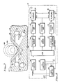
- Figure 8 is a block diagram of the circuit used by the empty container detector 10 of the present invention. It will be appreciated that the electronic components 10 not already specifically described are all mounted on the circuit board 34.
- a main pump unit 64 is used in conjunction with the detector 10 of the present invention. (It will be appreciated by those skilled in the art that the electronic components could alternatively be mounted in the main pump unit 64 instead of inside the detector 10 on the circuit board 34).
- the main pump unit 64 supplies power to the detector 10 via a V wire and a ground or earth connection. It should be noted that the various components of Figure 8 are connected to +V and ground, although these connections are not expressly shown in Figure 8.
- connection between the main pump unit 64 and the empty container detector 10 include a trigger signal, an I.D. signal, and an alarm signal. These five connections between the main pump unit 64 and the empty container detector 10 would be contained in the cord 30 ( Figures 1 and 2) extending from the empty container detector 10.
- the I.D. Signal is optional and in the preferred embodiment I.D. circuitry 66 is used to indicate to the main pump unit 64 either that the cord 30 from the detector 10 is properly connected to the main pump unit 64, or the type of device which is plugged in to the main pump unit 64.
- the I.D. circuitry 66 need only feed the +V signal back to the main pump unit 64 as the ID signal to indicate that the detector 10 is properly connected to the main pump unit 64. As such, if the main pump unit 64 does not detect +V on the I.D. Signal line, it will be an indication that the detector 10 is not properly connected to the main pump unit 64.
- the I.D. Circuitry 66 includes a resistor (not shown), with the size of the resistor indicating to the main pump unit 64 (by the returning current) which particular device is plugged into the main pump unit 64. For example, three different resistances could be used in three different devices which may be plugged into the main pump unit 64, with one of these three different devices being the detector 10 of the present invention.
- Firing circuitry 68 is included in the empty container detector 10 to conserve power. Rather than having the LED 38 on all the time, it may be strobed periodically by the firing circuitry 68 in response to the trigger signal from the main pump unit 64.
- the rate at which the LED 38 is strobed depends upon several factors, including tubing size and maximum flow rear. In the preferred embodiment, the rate is sufficiently fast to prevent an air bubble from moving through the segment of tubing 12 without being detected.
- the tube/on tube sensor 46 supplies an output to an inverting amplifier 70, which in turn provides an output which is the Data (D) input to a first D flip-flop 72.
- the Direct Reset (R) and Direct Set (S) inputs of the first D fli+p-flop 72 are both inactive (tied to ground).
- the LED sensor 42 supplies an output to an inverting amplifier 74, which in turn provides an output which is the Clock signal for both of the first D flip-flop 72 and a second D flip-flop 76.
- the Clock signal occurs when the signal from the LED sensor 42 has decayed to a predetermined light level which is less than the maximum light level.
- the inverting amplifier 74 provides the CLock signal when the decaying signal from the LED sensor 38 has dropped to the predetermined level, causing the system to take a reading of the liquid-in-tube sensor 50 at that time. This operation ensures that the measurement of light taken by the liquid-in-tube sensor 50 will always be taken at constant light level, which in the preferred embodiment is the point at which the light impulse from the LED 38 has fallen off to the predetermined level.
- the Q output from the first D flip-flop 72 is supplied to the second D flip-flop 76 as the R input.
- the liquid-in-tube sensor 50 supplies an output to an inverting amplifier 78, which in turn provides an output which is the D input to the second D flip-flop 76 .
- the S input to the second D flip-flop 76 is inactive (grounded).
- the Q output of the second D flip-flop 76 is supplied to the main pump unit 64 as the alarm signal.
- the output from the tube/no tube sensor 46 is high (indicating that the segment of tubing 12 is not properly installed), the output from the inverting amplifier 70 and the D input to the first D flip-flop 72 will be low. If the D input to the first D flip-flop 72 is low, then the Q output from the first D flip-flop 72 will be high .
- the Q output from the first D flip-flop 72 is the R input to the second D flip-flop 76, and if the R input to the second D flip-flop 76 is active (high), the Q output of the second D flip-flop 76 is always inactive (low).
- a low Q output from the second D flip-flop 76 will cause an alarm. It is therefore apparent that if the output of the tube/no tube sensor 46 is high, an alarm will be sounded regardless of the state of the liquid-in-tube sensor 50.
- the output Q of the first D flip-flop 72 will be inactive (low). In this case, the state of the liquid-in-tube sensor 50 will determine whether or not an alarm is sounded. If the output of the liquid in the tube sensor 50 is high (indicating that air is in the segment of tubing 12), the output of the inverting amplifier 78 will then be low. The output of the inverting amplifier 78 is the D input to the second D flip-flop 76, and if the D input to the second D flip-flop 76 is low, the Q output of the second D flip-flop 76 will be low, causing an alarm.
- the output of the liquid-in-tube sensor 50 is high (indicating that no air is contained in the segment of tubing 12)
- the output of the inverting amplifier 78 is high. Accordingly, the D input to the second D flip-flop 76 is high, and the Q output of the second D flip-flop 76 will be high, and no alarm will be sounded.
- circuit of Figure 8 represents only one of a number of different circuits which could be used to achieve the same result. The important thing is that; 1. wherever the output of the tube/no tube sensor 46 is high, an alarm be sounded (indicating that the segment of tubing 12 is not properly installed); and 2. when the output of the tube/no tube sensor 46 is low, an alarm is sounded when the output of the liquid-in-tube sensor 50 is high.
- a visual alarm mechanism and/or an audible alarm mechanism is contained in the main pump unit 64.
- the visible alarm mechanism could be a flashing light or a word on a screen indicating an alarm
- the audible alarm mechanism could be a buzzer, horn, or electrically generated tone.
- These mechanisms could of course alternatively be contained in the empty container detector 10 itself.
- the power supply and oscillator means to generate the trigger signal could also be contained in the empty container detector 10 itself.
- the present invention provides an empty container detection system which is simple and easy to use, clamping onto a fluid line immediately downstream from the fluid reservoir container.
- the system is capable of quickly, accurately and effectively detecting air in the fluid line regardless of whether the fluid being infused is opaque, translucent, or transparent.
Applications Claiming Priority (2)
| Application Number | Priority Date | Filing Date | Title |
|---|---|---|---|
| US07/206,232 US4884065A (en) | 1988-06-13 | 1988-06-13 | Monitor for detecting tube position and air bubbles in tube |
| US206232 | 1988-06-13 |
Publications (2)
| Publication Number | Publication Date |
|---|---|
| EP0346548A1 true EP0346548A1 (de) | 1989-12-20 |
| EP0346548B1 EP0346548B1 (de) | 1993-08-11 |
Family
ID=22765512
Family Applications (1)
| Application Number | Title | Priority Date | Filing Date |
|---|---|---|---|
| EP88311343A Expired - Lifetime EP0346548B1 (de) | 1988-06-13 | 1988-11-30 | Behälterleerzustandsdetektor |
Country Status (5)
| Country | Link |
|---|---|
| US (1) | US4884065A (de) |
| EP (1) | EP0346548B1 (de) |
| JP (1) | JPH01314573A (de) |
| CA (1) | CA1329896C (de) |
| DE (1) | DE3883226T2 (de) |
Cited By (13)
| Publication number | Priority date | Publication date | Assignee | Title |
|---|---|---|---|---|
| EP0491971A1 (de) * | 1990-12-20 | 1992-07-01 | Thomas Dipl. Ing. Bleeker | Anordnung zur Überwachung von mittels Drainageschläuchen abgeleiteten Körperflüssigkeiten |
| EP0522527A1 (de) * | 1991-07-10 | 1993-01-13 | Sharp Kabushiki Kaisha | Flüssigkeitslösung-Infusionssystem |
| EP0551088A1 (de) * | 1992-01-06 | 1993-07-14 | Baxter International Inc. | Peristaltische Pumpe mit verbesserter Schaltung zur Erkennung von falsch geladenen Schläuchen |
| EP0694163A1 (de) * | 1994-02-05 | 1996-01-31 | Baxter International Inc. | Detektor mit doppelsensor für luft in einer leitung |
| EP0742027A2 (de) * | 1995-05-12 | 1996-11-13 | Instrumentarium Oy | Leckprüfungsanordnung für die Verbindung mit einem Beatmungsgerät |
| US5788674A (en) * | 1996-03-05 | 1998-08-04 | Medication Delivery Devices, Inc. | Apparatus and method for limiting free-flow in an infusion system |
| WO2003103751A1 (en) * | 2002-06-10 | 2003-12-18 | Akzo Nobel N.V. | Needle-less injector |
| EP1829573A1 (de) * | 2006-03-02 | 2007-09-05 | Covidien AG | Pumpensatz mit sicherer Ladefunktion |
| EP1932554A1 (de) * | 2006-12-11 | 2008-06-18 | Covidien AG | Pumpensatz und Pumpe mit einer durch elektromagnetische Strahlung betätigten Sperre |
| EP1941923A1 (de) * | 2007-01-05 | 2008-07-09 | Covidien AG | Pumpenset zur Förderung einer Flüssigkeit für sicheres Einsetzen des Förderschlauches und Herstellung einer Komponente dafür |
| US7722562B2 (en) | 2006-03-02 | 2010-05-25 | Tyco Healthcare Group Lp | Pump set with safety interlock |
| US7846131B2 (en) | 2005-09-30 | 2010-12-07 | Covidien Ag | Administration feeding set and flow control apparatus with secure loading features |
| WO2011015228A1 (en) * | 2009-08-04 | 2011-02-10 | Stepra Ltd | An apparatus for verifying the identity of a final fluid product for medical or pharmaceutical use |
Families Citing this family (79)
| Publication number | Priority date | Publication date | Assignee | Title |
|---|---|---|---|---|
| JPH061152Y2 (ja) * | 1989-04-28 | 1994-01-12 | シャープ株式会社 | 輸液注入ポンプの空気探知機 |
| US5136280A (en) * | 1989-05-15 | 1992-08-04 | Teledyne Industries, Inc. | Switch status indicator and self tester |
| US5139482A (en) * | 1990-01-18 | 1992-08-18 | Simeon Paula S | Fluid infusion line monitor |
| US5059171A (en) * | 1990-06-21 | 1991-10-22 | Boc Health Care, Inc. | Bubble detection system |
| GB2248927B (en) * | 1990-10-17 | 1994-04-20 | Danby Medical Ltd | A device for detecting air in fluid conducting tubing |
| US5241189A (en) * | 1992-05-29 | 1993-08-31 | Eastman Kodak Company | Ink concentration sensor for maintaining dye concentration in an ink jet printer |
| US5680111A (en) * | 1994-02-05 | 1997-10-21 | Baxter International Inc. | Dual sensor air-in-line detector |
| US5539386A (en) * | 1994-03-07 | 1996-07-23 | J-Kem Electronics, Inc. | Sensor for detecting air/liquid transitions in a transparent tubing |
| US5672887A (en) * | 1995-11-29 | 1997-09-30 | Shaw; Benjamin G. | Optical detector for air in fluid line the same |
| JP2001517964A (ja) * | 1995-12-04 | 2001-10-09 | アルフエームド インコーポレイテツド | 処分可能なチューブ輸送手段およびサイズ指示手段を有する輸注ポンプ |
| US5868710A (en) | 1996-11-22 | 1999-02-09 | Liebel Flarsheim Company | Medical fluid injector |
| US5969600A (en) * | 1997-02-19 | 1999-10-19 | Ranco Inc. Of Delware | Dangerous condition warning device incorporating a time-limited hush mode of operation to defeat an audible low battery warning signal |
| US5896091A (en) * | 1997-02-19 | 1999-04-20 | Ranco Inc. Of Delaware | Dangerous condition warning device incorporating a replaceable sensor and apparatus to prevent the sensor from being improperly installed |
| US5912626A (en) * | 1997-02-19 | 1999-06-15 | Soderlund; Ernest E. | Dangerous condition warning device incorporating provision for permanently retaining printed protocol instructions |
| US5966078A (en) * | 1997-02-19 | 1999-10-12 | Ranco Inc. | Battery saving circuit for a dangerous condition warning device |
| US5966079A (en) * | 1997-02-19 | 1999-10-12 | Ranco Inc. Of Delaware | Visual indicator for identifying which of a plurality of dangerous condition warning devices has issued an audible low battery warning signal |
| US5886638A (en) * | 1997-02-19 | 1999-03-23 | Ranco Inc. Of Delaware | Method and apparatus for testing a carbon monoxide sensor |
| US5960129A (en) * | 1997-12-22 | 1999-09-28 | Bayer Corporation | Method and apparatus for detecting liquid and gas segment flow through a tube |
| GB9803299D0 (en) * | 1998-02-18 | 1998-04-08 | Gallagher George | Improved method and apparatus for monitoring intravenous drips |
| US6231320B1 (en) | 1998-06-12 | 2001-05-15 | Abbott Laboratories | Drug infusion pumping cassette latching mechanism |
| US6142008A (en) * | 1998-06-12 | 2000-11-07 | Abbott Laboratories | Air bubble sensor |
| SE513522C2 (sv) * | 1998-09-10 | 2000-09-25 | Gambro Ab | Anordning för övervakande av ett fluidrör |
| US6877713B1 (en) | 1999-07-20 | 2005-04-12 | Deka Products Limited Partnership | Tube occluder and method for occluding collapsible tubes |
| US6464666B1 (en) * | 1999-10-08 | 2002-10-15 | Augustine Medical, Inc. | Intravenous fluid warming cassette with stiffening member and integral handle |
| AU2002247151A1 (en) * | 2001-02-15 | 2002-08-28 | Acist Medical Systems, Inc. | Systems and methods for detection and measurement of elements in a medium |
| US6531708B1 (en) * | 2001-04-16 | 2003-03-11 | Zevex, Inc. | Optical bubble detection system |
| US6659976B2 (en) * | 2001-04-16 | 2003-12-09 | Zevek, Inc. | Feeding set adaptor |
| DE10226334B4 (de) * | 2002-06-13 | 2005-09-01 | Pari GmbH Spezialisten für effektive Inhalation | Vorrichtung zur Erfassung von Parametern eines Aerosols, insbesondere bei Inhalationstherapiegeräten |
| US20050195087A1 (en) * | 2004-03-04 | 2005-09-08 | Thompson Holly R. | Air-in-line detector with warning device |
| DE602005027374D1 (de) | 2004-10-18 | 2011-05-19 | Kidde Portable Equipment Inc | Frequenzkommunikationsschema in lebenserhaltenden vorrichtungen |
| CA2584498C (en) | 2004-10-18 | 2013-12-10 | Walter Kidde Portable Equipment, Inc. | Low battery warning silencing in life safety devices |
| DE602005020044D1 (de) * | 2004-10-18 | 2010-04-29 | Kidde Portable Equipment Inc | Gateway-einrichtung zur verbindung eines systems mit live-safety-einrichtungen |
| US7763005B2 (en) | 2006-03-02 | 2010-07-27 | Covidien Ag | Method for using a pump set having secure loading features |
| US7722573B2 (en) * | 2006-03-02 | 2010-05-25 | Covidien Ag | Pumping apparatus with secure loading features |
| US7927304B2 (en) * | 2006-03-02 | 2011-04-19 | Tyco Healthcare Group Lp | Enteral feeding pump and feeding set therefor |
| US20080103445A1 (en) * | 2006-09-29 | 2008-05-01 | Blaine David H | Method and Apparatus for Detecting Air Bubbles |
| US7726174B2 (en) * | 2006-10-24 | 2010-06-01 | Zevex, Inc. | Universal air bubble detector |
| US7927302B2 (en) * | 2007-04-24 | 2011-04-19 | Arizant Healthcare Inc. | High flow rate infusion unit and heat exchanger |
| EP2183564B1 (de) | 2007-08-24 | 2019-01-02 | Moog Inc. | Luft- und flüssigkeitsultraschalldetektor |
| EP2219533A4 (de) | 2007-12-07 | 2013-12-18 | Zevex Inc | Verfahren zur auslösung einer querbewegung in wandlern vom langevin-typ mit spaltelektroden-behandlung von keramischen elementen |
| US9026370B2 (en) | 2007-12-18 | 2015-05-05 | Hospira, Inc. | User interface improvements for medical devices |
| US9078971B2 (en) | 2008-01-23 | 2015-07-14 | Deka Products Limited Partnership | Medical treatment system and methods using a plurality of fluid lines |
| CA2712947C (en) | 2008-01-23 | 2017-07-25 | Deka Products Limited Partnership | Fluid volume determination for medical treatment system |
| WO2010091314A2 (en) | 2009-02-06 | 2010-08-12 | Zevex, Inc. | Air bubble detector |
| CA2779296C (en) | 2009-10-30 | 2018-02-13 | Deka Products Limited Partnership | Apparatus and method for detecting disconnection of an intravascular access device |
| US8154274B2 (en) | 2010-05-11 | 2012-04-10 | Tyco Healthcare Group Lp | Safety interlock |
| EP2591385B1 (de) | 2010-07-07 | 2017-10-11 | DEKA Products Limited Partnership | Medizinisches behandlungssystem und verfahren anhand der verwendung mehrerer flüssigkeitsleitungen |
| US9188528B2 (en) | 2010-09-21 | 2015-11-17 | Ab Elektronik Sachsen Gmbh | Sensor for monitoring a medium |
| US20120098668A1 (en) * | 2010-10-22 | 2012-04-26 | Peng Chen | Infusion monitoring alarm and method for monitoring and alarming for intravenous infusion |
| US9999717B2 (en) | 2011-05-24 | 2018-06-19 | Deka Products Limited Partnership | Systems and methods for detecting vascular access disconnection |
| SG195155A1 (en) | 2011-05-24 | 2013-12-30 | Deka Products Lp | Blood treatment systems and methods |
| WO2013028497A1 (en) | 2011-08-19 | 2013-02-28 | Hospira, Inc. | Systems and methods for a graphical interface including a graphical representation of medical data |
| EP3753588A1 (de) | 2011-11-04 | 2020-12-23 | DEKA Products Limited Partnership | System und verfahren zur medizinischen behandlung unter verwendung einer vielzahl von flüssigkeitsleitungen |
| WO2013090709A1 (en) | 2011-12-16 | 2013-06-20 | Hospira, Inc. | System for monitoring and delivering medication to a patient and method of using the same to minimize the risks associated with automated therapy |
| ES2741725T3 (es) | 2012-03-30 | 2020-02-12 | Icu Medical Inc | Sistema de detección de aire y método para detectar aire en una bomba de un sistema de infusión |
| US10463788B2 (en) | 2012-07-31 | 2019-11-05 | Icu Medical, Inc. | Patient care system for critical medications |
| GB201300362D0 (en) * | 2013-01-09 | 2013-02-20 | Reckitt Benckiser Uk Ltd | Low cost senor system |
| US10046112B2 (en) | 2013-05-24 | 2018-08-14 | Icu Medical, Inc. | Multi-sensor infusion system for detecting air or an occlusion in the infusion system |
| AU2014274146B2 (en) | 2013-05-29 | 2019-01-24 | Icu Medical, Inc. | Infusion system which utilizes one or more sensors and additional information to make an air determination regarding the infusion system |
| EP3003442B1 (de) | 2013-05-29 | 2020-12-30 | ICU Medical, Inc. | Infusionssystem und verfahren zur verwendung zur verhinderung der übersättigung eines analog-digital-wandlers |
| JP6302255B2 (ja) * | 2014-01-16 | 2018-03-28 | 株式会社キーエンス | カートリッジ式インクジェット記録装置 |
| ES2776363T3 (es) | 2014-02-28 | 2020-07-30 | Icu Medical Inc | Sistema de infusión y método que utiliza detección óptica de aire en línea de doble longitud de onda |
| WO2015184366A1 (en) | 2014-05-29 | 2015-12-03 | Hospira, Inc. | Infusion system and pump with configurable closed loop delivery rate catch-up |
| US10046354B2 (en) * | 2014-09-19 | 2018-08-14 | Chiba Machine Industry Corporation | Blade device, and printer and coating apparatus provided with said blade device |
| US11344668B2 (en) | 2014-12-19 | 2022-05-31 | Icu Medical, Inc. | Infusion system with concurrent TPN/insulin infusion |
| US10850024B2 (en) | 2015-03-02 | 2020-12-01 | Icu Medical, Inc. | Infusion system, device, and method having advanced infusion features |
| EP4085944A1 (de) | 2016-05-13 | 2022-11-09 | ICU Medical, Inc. | Infusionspumpensystem mit gemeinsamer leitung zur automatischen spülung |
| WO2017214441A1 (en) | 2016-06-10 | 2017-12-14 | Icu Medical, Inc. | Acoustic flow sensor for continuous medication flow measurements and feedback control of infusion |
| US10072962B2 (en) | 2016-07-05 | 2018-09-11 | Ecolab Usa Inc. | Liquid out-of-product alarm system and method |
| WO2018022489A1 (en) * | 2016-07-25 | 2018-02-01 | The Regents Of The University Of California | Automated optical detection of air leaks in chest tube drainage systems |
| IL305004A (en) * | 2017-03-17 | 2023-10-01 | Irras Ab | Fluid exchange system and related methods |
| US11517734B2 (en) * | 2017-06-21 | 2022-12-06 | Kristin Rossodivito | System and method for detecting air embolisms in lines for hemodynamic monitoring |
| JP6986266B2 (ja) * | 2017-11-14 | 2021-12-22 | ジーニアルライト株式会社 | 体液分析装置 |
| US10089055B1 (en) | 2017-12-27 | 2018-10-02 | Icu Medical, Inc. | Synchronized display of screen content on networked devices |
| US11278671B2 (en) | 2019-12-04 | 2022-03-22 | Icu Medical, Inc. | Infusion pump with safety sequence keypad |
| CA3189781A1 (en) | 2020-07-21 | 2022-01-27 | Icu Medical, Inc. | Fluid transfer devices and methods of use |
| US11135360B1 (en) | 2020-12-07 | 2021-10-05 | Icu Medical, Inc. | Concurrent infusion with common line auto flush |
| KR20230148419A (ko) * | 2021-02-26 | 2023-10-24 | 바이엘 헬쓰케어 엘엘씨 | 유체 인젝터용 공기 검출 및 측정 시스템 |
| CA3223779A1 (en) * | 2021-06-17 | 2022-12-22 | Bayer Healthcare Llc | System and method for detecting fluid type in tubing for fluid injector apparatus |
Citations (5)
| Publication number | Priority date | Publication date | Assignee | Title |
|---|---|---|---|---|
| WO1982000591A1 (en) * | 1980-08-25 | 1982-03-04 | Travenol Lab Baxter | System for detecting bubble formation in clear and opaque fluids |
| US4366384A (en) * | 1980-06-18 | 1982-12-28 | Cutter Laboratories, Inc. | Air bubble detector |
| EP0181272A2 (de) * | 1984-10-31 | 1986-05-14 | Hospal Ag | Vorrichtung zur Anzeige von Blasen im Blut |
| EP0196822A2 (de) * | 1985-03-28 | 1986-10-08 | Imed Corporation | Detektor für Luft in einer Leitung |
| EP0238809A2 (de) * | 1986-03-24 | 1987-09-30 | Gambro Ab | Detektorsystem zur Überwachung eines Flüssigkeitsrohres, anschliessbar an einen Monitor |
Family Cites Families (4)
| Publication number | Priority date | Publication date | Assignee | Title |
|---|---|---|---|---|
| US3636360A (en) * | 1968-05-13 | 1972-01-18 | Hitachi Ltd | Apparatus for detection of liquid level in transparent tube comprising photocell located to receive light which has been totally reflected |
| US4312341A (en) * | 1979-12-13 | 1982-01-26 | Baxter Travenol Laboratories, Inc. | Bubble detector |
| US4440022A (en) * | 1981-10-14 | 1984-04-03 | Smiths Industries Public Limited Company | Liquid-level detection |
| EP0228217A1 (de) * | 1985-12-18 | 1987-07-08 | LUCAS INDUSTRIES public limited company | Flüssigkeitsstandanzeiger |
-
1988
- 1988-06-13 US US07/206,232 patent/US4884065A/en not_active Expired - Lifetime
- 1988-11-30 DE DE88311343T patent/DE3883226T2/de not_active Expired - Fee Related
- 1988-11-30 EP EP88311343A patent/EP0346548B1/de not_active Expired - Lifetime
- 1988-12-01 CA CA000584263A patent/CA1329896C/en not_active Expired - Lifetime
- 1988-12-15 JP JP63317587A patent/JPH01314573A/ja active Pending
Patent Citations (5)
| Publication number | Priority date | Publication date | Assignee | Title |
|---|---|---|---|---|
| US4366384A (en) * | 1980-06-18 | 1982-12-28 | Cutter Laboratories, Inc. | Air bubble detector |
| WO1982000591A1 (en) * | 1980-08-25 | 1982-03-04 | Travenol Lab Baxter | System for detecting bubble formation in clear and opaque fluids |
| EP0181272A2 (de) * | 1984-10-31 | 1986-05-14 | Hospal Ag | Vorrichtung zur Anzeige von Blasen im Blut |
| EP0196822A2 (de) * | 1985-03-28 | 1986-10-08 | Imed Corporation | Detektor für Luft in einer Leitung |
| EP0238809A2 (de) * | 1986-03-24 | 1987-09-30 | Gambro Ab | Detektorsystem zur Überwachung eines Flüssigkeitsrohres, anschliessbar an einen Monitor |
Cited By (26)
| Publication number | Priority date | Publication date | Assignee | Title |
|---|---|---|---|---|
| EP0491971A1 (de) * | 1990-12-20 | 1992-07-01 | Thomas Dipl. Ing. Bleeker | Anordnung zur Überwachung von mittels Drainageschläuchen abgeleiteten Körperflüssigkeiten |
| EP0522527A1 (de) * | 1991-07-10 | 1993-01-13 | Sharp Kabushiki Kaisha | Flüssigkeitslösung-Infusionssystem |
| EP0551088A1 (de) * | 1992-01-06 | 1993-07-14 | Baxter International Inc. | Peristaltische Pumpe mit verbesserter Schaltung zur Erkennung von falsch geladenen Schläuchen |
| US5312334A (en) * | 1992-01-06 | 1994-05-17 | Sharp Kabushiki Kaisha | Peristaltic pump apparatus having an improved misloaded IV tube detecting circuit |
| EP0694163A4 (de) * | 1994-02-05 | 2000-02-23 | Baxter Int | Detektor mit doppelsensor für luft in einer leitung |
| EP0694163A1 (de) * | 1994-02-05 | 1996-01-31 | Baxter International Inc. | Detektor mit doppelsensor für luft in einer leitung |
| EP0742027A2 (de) * | 1995-05-12 | 1996-11-13 | Instrumentarium Oy | Leckprüfungsanordnung für die Verbindung mit einem Beatmungsgerät |
| EP0742027A3 (de) * | 1995-05-12 | 1997-03-26 | Instrumentarium Oy | Leckprüfungsanordnung für die Verbindung mit einem Beatmungsgerät |
| US5661231A (en) * | 1995-05-12 | 1997-08-26 | Instrumentarium Oy | Arrangement for leak testing place in connection with a ventilator |
| US5788674A (en) * | 1996-03-05 | 1998-08-04 | Medication Delivery Devices, Inc. | Apparatus and method for limiting free-flow in an infusion system |
| US7601137B2 (en) | 2002-06-10 | 2009-10-13 | Intervet International B.V. | Needle-less injector |
| WO2003103751A1 (en) * | 2002-06-10 | 2003-12-18 | Akzo Nobel N.V. | Needle-less injector |
| US7846131B2 (en) | 2005-09-30 | 2010-12-07 | Covidien Ag | Administration feeding set and flow control apparatus with secure loading features |
| US7758551B2 (en) | 2006-03-02 | 2010-07-20 | Covidien Ag | Pump set with secure loading features |
| EP2145639A1 (de) * | 2006-03-02 | 2010-01-20 | Covidien AG | Pumpensatz mit sicherer Ladefunktion |
| US7722562B2 (en) | 2006-03-02 | 2010-05-25 | Tyco Healthcare Group Lp | Pump set with safety interlock |
| EP1829573A1 (de) * | 2006-03-02 | 2007-09-05 | Covidien AG | Pumpensatz mit sicherer Ladefunktion |
| CN101069760B (zh) * | 2006-03-02 | 2011-05-11 | 舍伍德服务股份公司 | 具有安全装载特性的泵器件 |
| AU2007240235B2 (en) * | 2006-12-11 | 2009-05-14 | Cardinal Health 529, Llc | Pump set and pump with electromagnetic radiation operated interlock |
| EP1932554A1 (de) * | 2006-12-11 | 2008-06-18 | Covidien AG | Pumpensatz und Pumpe mit einer durch elektromagnetische Strahlung betätigten Sperre |
| EP2298383A1 (de) * | 2006-12-11 | 2011-03-23 | Covidien AG | Pumpensatz und Pumpe mit einer durch elektromagnetische Strahlung betätigten Sperre |
| CN101254324B (zh) * | 2006-12-11 | 2011-03-23 | 科维迪恩股份公司 | 具有电磁辐射操控的联锁装置的泵组件和泵 |
| EP1941923A1 (de) * | 2007-01-05 | 2008-07-09 | Covidien AG | Pumpenset zur Förderung einer Flüssigkeit für sicheres Einsetzen des Förderschlauches und Herstellung einer Komponente dafür |
| US8021336B2 (en) | 2007-01-05 | 2011-09-20 | Tyco Healthcare Group Lp | Pump set for administering fluid with secure loading features and manufacture of component therefor |
| WO2011015228A1 (en) * | 2009-08-04 | 2011-02-10 | Stepra Ltd | An apparatus for verifying the identity of a final fluid product for medical or pharmaceutical use |
| US8881980B2 (en) | 2009-08-04 | 2014-11-11 | STEPRA Ltd. | Apparatus for verifying the identity of a final fluid product for medical or pharmaceutical use |
Also Published As
| Publication number | Publication date |
|---|---|
| DE3883226T2 (de) | 1993-11-25 |
| CA1329896C (en) | 1994-05-31 |
| EP0346548B1 (de) | 1993-08-11 |
| JPH01314573A (ja) | 1989-12-19 |
| US4884065A (en) | 1989-11-28 |
| DE3883226D1 (de) | 1993-09-16 |
Similar Documents
| Publication | Publication Date | Title |
|---|---|---|
| EP0346548B1 (de) | Behälterleerzustandsdetektor | |
| US3935876A (en) | Air leak detector | |
| JP3321620B2 (ja) | 液体送り出しシステム中の空気の検知のための装置及び方法 | |
| US4920336A (en) | Method and apparatus for monitoring the level of the contents in a container | |
| US3563090A (en) | Drop monitor | |
| US5140862A (en) | Injection pump calibration device | |
| JP2773875B2 (ja) | 腸管外液剤容器のためのスパイク | |
| US4623331A (en) | Apparatus for the registration of drops in an infusion device | |
| EP0419094B1 (de) | Mit Ultraschall arbeitender Luftmengendetektor für ein Medikamenten-Infusionssystem | |
| US5445622A (en) | Flow switch device for medical applications | |
| US4775368A (en) | Infusion device | |
| US6290681B1 (en) | Flow monitoring device for medical application | |
| US4383252A (en) | Intravenous drip feed monitor | |
| US5002539A (en) | IV rate meter | |
| CA1240755A (en) | Empty container detector with drop sensor | |
| US4114144A (en) | Automatic air-in-line fluid detector | |
| CA2102424C (en) | Drop detection method and apparatus | |
| US4681569A (en) | IV rate meter | |
| ES2418630T3 (es) | Detección de envase vacío usando un sensor de presión del lado del envase | |
| US6750468B2 (en) | Optical bubble detection system | |
| US6422057B1 (en) | Drug pump testing system and methods | |
| EP0453211B1 (de) | Mit Ultraschall arbeitender Luftmengendetektor für ein Medikamenten-Infusionssystem | |
| CA1111122A (en) | Drop discriminator system | |
| GB2416837A (en) | A fluid detector having lateral offset along its emitter to receiver radiation paths | |
| US20090093786A1 (en) | Method for detecting the occlusion of a tubing for a device for administering physiological liquids |
Legal Events
| Date | Code | Title | Description |
|---|---|---|---|
| PUAI | Public reference made under article 153(3) epc to a published international application that has entered the european phase |
Free format text: ORIGINAL CODE: 0009012 |
|
| AK | Designated contracting states |
Kind code of ref document: A1 Designated state(s): DE FR GB IT NL SE |
|
| 17P | Request for examination filed |
Effective date: 19891222 |
|
| 17Q | First examination report despatched |
Effective date: 19910503 |
|
| GRAA | (expected) grant |
Free format text: ORIGINAL CODE: 0009210 |
|
| STAA | Information on the status of an ep patent application or granted ep patent |
Free format text: STATUS: THE PATENT HAS BEEN GRANTED |
|
| ITF | It: translation for a ep patent filed |
Owner name: BARZANO' E ZANARDO ROMA S.P.A. |
|
| AK | Designated contracting states |
Kind code of ref document: B1 Designated state(s): DE FR GB IT NL SE |
|
| PG25 | Lapsed in a contracting state [announced via postgrant information from national office to epo] |
Ref country code: SE Effective date: 19930811 |
|
| RIN1 | Information on inventor provided before grant (corrected) |
Inventor name: LAUER, NORRIS A. Inventor name: PINTO, DAVID A. Inventor name: CROUSE, RONALD J. |
|
| REF | Corresponds to: |
Ref document number: 3883226 Country of ref document: DE Date of ref document: 19930916 |
|
| ET | Fr: translation filed | ||
| PLBE | No opposition filed within time limit |
Free format text: ORIGINAL CODE: 0009261 |
|
| 26N | No opposition filed | ||
| PGFP | Annual fee paid to national office [announced via postgrant information from national office to epo] |
Ref country code: GB Payment date: 19941017 Year of fee payment: 7 |
|
| PGFP | Annual fee paid to national office [announced via postgrant information from national office to epo] |
Ref country code: FR Payment date: 19941114 Year of fee payment: 7 |
|
| PGFP | Annual fee paid to national office [announced via postgrant information from national office to epo] |
Ref country code: NL Payment date: 19941130 Year of fee payment: 7 Ref country code: DE Payment date: 19941130 Year of fee payment: 7 |
|
| NLT1 | Nl: modifications of names registered in virtue of documents presented to the patent office pursuant to art. 16 a, paragraph 1 |
Owner name: SIEMENS INFUSION SYSTEMS LIMITED TE SYLMAR, CALIFO |
|
| NLS | Nl: assignments of ep-patents |
Owner name: IVAC CORPORATION TE SAN DIEGO, CALIFORNIE, VER. ST |
|
| REG | Reference to a national code |
Ref country code: FR Ref legal event code: TP Ref country code: FR Ref legal event code: CD |
|
| REG | Reference to a national code |
Ref country code: GB Ref legal event code: 732E |
|
| ITPR | It: changes in ownership of a european patent |
Owner name: CESSIONE;IVAC CORPORATION |
|
| PG25 | Lapsed in a contracting state [announced via postgrant information from national office to epo] |
Ref country code: GB Effective date: 19951130 |
|
| PG25 | Lapsed in a contracting state [announced via postgrant information from national office to epo] |
Ref country code: NL Effective date: 19960601 |
|
| GBPC | Gb: european patent ceased through non-payment of renewal fee |
Effective date: 19951130 |
|
| PG25 | Lapsed in a contracting state [announced via postgrant information from national office to epo] |
Ref country code: FR Effective date: 19960731 |
|
| NLV4 | Nl: lapsed or anulled due to non-payment of the annual fee |
Effective date: 19960601 |
|
| PG25 | Lapsed in a contracting state [announced via postgrant information from national office to epo] |
Ref country code: DE Effective date: 19960801 |
|
| REG | Reference to a national code |
Ref country code: FR Ref legal event code: ST |
|
| REG | Reference to a national code |
Ref country code: FR Ref legal event code: CD Ref country code: FR Ref legal event code: CA |
|
| PG25 | Lapsed in a contracting state [announced via postgrant information from national office to epo] |
Ref country code: IT Free format text: LAPSE BECAUSE OF NON-PAYMENT OF DUE FEES;WARNING: LAPSES OF ITALIAN PATENTS WITH EFFECTIVE DATE BEFORE 2007 MAY HAVE OCCURRED AT ANY TIME BEFORE 2007. THE CORRECT EFFECTIVE DATE MAY BE DIFFERENT FROM THE ONE RECORDED. Effective date: 20051130 |