EP0346527A2 - Respirateur - Google Patents
Respirateur Download PDFInfo
- Publication number
- EP0346527A2 EP0346527A2 EP88120039A EP88120039A EP0346527A2 EP 0346527 A2 EP0346527 A2 EP 0346527A2 EP 88120039 A EP88120039 A EP 88120039A EP 88120039 A EP88120039 A EP 88120039A EP 0346527 A2 EP0346527 A2 EP 0346527A2
- Authority
- EP
- European Patent Office
- Prior art keywords
- valve
- peep
- pressure
- breathing
- gas
- Prior art date
- Legal status (The legal status is an assumption and is not a legal conclusion. Google has not performed a legal analysis and makes no representation as to the accuracy of the status listed.)
- Granted
Links
Images
Classifications
-
- A—HUMAN NECESSITIES
- A61—MEDICAL OR VETERINARY SCIENCE; HYGIENE
- A61M—DEVICES FOR INTRODUCING MEDIA INTO, OR ONTO, THE BODY; DEVICES FOR TRANSDUCING BODY MEDIA OR FOR TAKING MEDIA FROM THE BODY; DEVICES FOR PRODUCING OR ENDING SLEEP OR STUPOR
- A61M16/00—Devices for influencing the respiratory system of patients by gas treatment, e.g. ventilators; Tracheal tubes
Definitions
- the invention relates to a breathing apparatus according to the preamble of claim 1.
- EP-PS 0 112 979 describes a breathing apparatus which is used to restore spontaneous breathing by patients.
- the known device has an inspiratory and an expiratory branch, with a continuously positive airway pressure (CPAP) being adjustable at the peep level.
- CPAP continuously positive airway pressure
- Means for generating a continuously flowing gas stream according to the high-flow or low-flow principle are provided in the inspiratory branch.
- the expiratory branch can be closed by an expiratory valve which responds to a gas pressure at peep level.
- an additional peep valve was arranged in the known device in the inspiratory branch, the expiratory valve arranged at the end of the expiratory branch and thus the pressure in the expiratory branch being controlled at a peep level by a control device comparing the pressure in the inspiratory and expiratory branch.
- An additional one-way valve in the inspiratory branch separates it from the patient in the expiratory phase, with the continuously flowing gas stream from the inspiratory branch during the expiratory phase can be derived via the control valve which determines the peep level and is arranged in the inspiratory branch.
- the known device also contains an additional pressure-keeping device, by means of which a minimal gas flow (low-flow principle) can be set, with an additional supply of gas when the patient is required according to the demand principle.
- a minimal gas flow low-flow principle
- the patient With the high-flow CPAP, the patient is offered a constant gas flow, the desired overpressure at peep level being adjustable by a peep valve located at the end of the expiration branch.
- the constantly flowing gas flow in the high-flow CPAP device is in the generally adjusted to the highest possible removal of the patient in the inspiration phase, so that a high gas consumption results from the fact that the gas flows out of the overflow valve (peep valve) unused in the expiration phase.
- a pressure stabilizer is additionally provided, which can supply the patient with a further gas volume if necessary via a control with pressure measuring devices in the expiratory branch to the constantly flowing gas stream during the inspiration phase.
- This basically corresponds to the so-called demand principle, in which the inspiratory gas flow desired by the patient is offered as required via a pressure sensor and a controllable inspiration valve.
- the invention is based on the object of avoiding the abovementioned disadvantages and, in particular, of proposing a breathing apparatus which is extremely simple in construction, with an improvement in airway resistance in the expiratory phase.
- the breathing aid according to the invention has the advantage over the known devices that the complete expiratory branch, which is otherwise considered necessary, is eliminated. Rather, the inspiratory branch is redesigned in such a way that it can cope with the task without disadvantages but with advantages.
- the peep level is set by a peep valve provided in the inspiratory branch, the peep valve arranged here primarily having the task of ensuring the constant gas flow present in the inspiratory branch (high-flow principle). to be derived as an overflow valve during the expiration phase.
- the control of the expiration valve arranged at the end of the expiration branch at the peep level must, however, also take place in the known device via the peep valve arranged in the inspiratory branch with the pressure losses associated therewith.
- the inspiratory branch is closed by a one-way valve or check valve in the known device.
- a separate expiratory branch is completely eliminated, ie the expiration valve is arranged directly in the inspiratory branch in the area of the patient connection piece, the expiration valve being set to the peep level.
- the disadvantages mentioned are avoided and in particular the resistances of the expiration line and control line are completely eliminated. Due to the close proximity of the expiration valve to the patient, the peep level can be extremely fine be produced so that a low patient burden is made possible. By omitting the components in the expiratory branch, the entire device is still cheaper.
- the peep valve arranged directly on the patient is designed as an overflow valve controlled at peep level.
- the peep level is set by a separate peep valve, i. H. there is a decoupling of the valve resistances between the very sensitive overflow valve and the peep valve which determines the peep level. If, for example, a spring-loaded adjustable peep valve is used directly as an expiration valve according to sub-claim 6, this does solve the task, but it is the less sensitive solution.
- a spring-loaded peep valve creates a dynamic pressure which, due to the inertia this system generates a higher back pressure than, for example, in a diaphragm control according to subclaim 5.
- the pressure chamber of the peep valve which is set at peep level is flowed with oxygen or air via a control line with throttle and / or pressure reducer.
- a constant pressure device is provided as a weather balloon, breathing bag or as a spring or force-loaded bellows.
- This additional reservoir which is provided with a fresh gas filling, on the one hand keeps the constantly flowing gas flow to a minimum, and on the other hand pressure fluctuations around the peep level or additionally necessary breathing air are made available.
- breathing bags or weather balloons have a filling volume of approx. 3 to 40 l of gas.
- this reservoir is filled at least temporarily with fresh gas from the constantly flowing gas flow and thus relieves the airway resistance.
- subclaim 7 it is advantageous to arrange a further output valve which can be set to the peep level between the check valve and the constant pressure device in order to serve as an overflow valve for the constantly flowing gas stream.
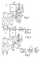
- the inspiratory branch 3 also contains a pressure constant device 11 as a reservoir or memory, which is designed as a bellows, the line 10 opening into the constant pressure device 11.
- a further line 12 leads from this constant pressure device 11 via a one-way valve or check valve 13 to the hose system 5 of the patient connector 4.
- FIG. 2 The simpler and basic design of the invention according to FIG. 2 provides that in the inspiratory branch 3, directly in the area of the patient, a connecting piece 14 is provided for an expiration valve 15, the expiration valve 15 being designed as a peep valve 15.
- the valve cover 16 closes the connecting flange 14 with a force which is set to the peep level (approx. 5 to 10 mbar).
- the pressure force of the valve cover 16 and thus the peep level by means of a spring 17 can rotatable plunger 18 can be adjusted very finely by means of the adjusting wheel 19.
- the breathing air flows via line 20 against the pressure of the peep valve 15 (peep level) to the outside (arrow 21).
- the peep level is set in a separate pressure control unit 22, which controls the peep level via a control line 23 in a diaphragm valve 24.
- oxygen or air is branched off via a control gas line 25 in front of the two pressure reducers 9 of the inspiratory branch (no influence on pressure) and guided into a pressure chamber 27 of the peep valve 28 via a separate pressure reducer 9 'and possibly via a throttle valve 26 designed as a fine regulating valve.
- the pressure reducer 9 'and the throttle valve 26 can be about Constantly flow 2 to 4 l of air into pressure chamber 27.
- the separate, spring-loaded peep valve 28 which is basically constructed in the same way as the peep valve 15 (see FIG. 2), allows a precisely set peep level to be created in the pressure chamber 27. The excess air flows out of line 29 into the open (arrow 30).
- the diaphragm valve 24 has an upper pressure chamber 31, which is connected directly or via the control line 23 to the pressure chamber 27 set at the peep level.
- the pressure chamber 31 is closed at the lower end by a sensitive membrane 32 which closes the sealing surface of the connecting flange 14.
- the expiration valve 24 designed as a diaphragm valve 24 in FIG. 1 is therefore decoupled from the actual setting of the peep level by the pressure control unit 22 with a separate peep valve 28.
- the device has a pressure-maintaining device 11, which can be designed as a weather balloon, breathing bag or also as a spring-loaded bellows.
- a pressure-maintaining device 11 which can be designed as a weather balloon, breathing bag or also as a spring-loaded bellows.
- This force 34 can be generated by a weight 35 (FIG. 2) on the bellows 11.
- a one-armed lever system 36 with a pivot point 37 and a lever arm 38 can be used instead of the weight 35 for generating a uniform pressure level in the bellows 11.
- This embodiment is only shown in FIG. 2, for example. It applies equally to FIG. 1.
- a weight 39 displaceable on the lever arm 38 can be used to generate a different torque 40 and thus to exert a force on the bellows 11.
- a spring 41 adjustable in spring force can also be used. The different force effects produce a different, but constant pressure in the bellows 11.
- the pressure maintenance device in the inspiratory branch has the function of a buffer, i. H. the breathing apparatus according to the invention can be used both in high-flow and in low-flow operation.
- the reservoir formed by the constant pressure device has the task of equalizing pressure fluctuations around the peep level and additionally providing the necessary breathing air in the event of a possible low-flow operation.
- the special embodiment as shown in FIG. 2 by way of example, keeps the ventilation pressure set constant regardless of the travel of the bellows 11. This is not possible with a normal breathing bag or weather balloon.
- Fig. 1 the isolation valves 48 to 51 are shown as an additional measure.
- a first separation point 48 is arranged in front of the one-way valve 13 and a second separation point 49 behind the expiration valve 24.
- the area which is in direct contact with the patient is designed to be exchangeable so that this part of the device can be supplied for cleaning.
- a further separation point 50 can be provided on the patient connector 4, which is used to connect a mask or a tube. Finally, a separation point 51 is provided in order to be able to disconnect the peep valve 28.
- the device according to the invention works as follows: In the inspiratory phase (inhalation), the constantly flowing gas stream flows in the inspiratory branch according to the high-flow CPAP principle via the constant pressure device 11 and the line 12 to the patient 2, the force-assisted constant pressure device or bellows 11 also allows gas to flow from this reservoir at constant pressure if necessary.
- the necessary constant pressure is generated by means of the weight system on the bellows 11. This also enables low-flow operation with a lower constant gas flow, since the pressure-constant device compensates for or provides pressure fluctuations and additionally required breathing gas.
- the continuously positive airway pressure (CPAP) at the peep level is set by the expiration valve 24, 15, a peep valve 15 (FIG. 2) or an overflow valve 24 (FIG. 1) optionally being used as the expiration valve. 1 is controlled by a separate peep valve 28 via a control line 23 as described.
- the invention is not restricted to the exemplary embodiment shown and described. Rather, it also encompasses all professional refinements and developments without their own inventive content.
Landscapes
- Health & Medical Sciences (AREA)
- Emergency Medicine (AREA)
- Pulmonology (AREA)
- Engineering & Computer Science (AREA)
- Anesthesiology (AREA)
- Biomedical Technology (AREA)
- Heart & Thoracic Surgery (AREA)
- Hematology (AREA)
- Life Sciences & Earth Sciences (AREA)
- Animal Behavior & Ethology (AREA)
- General Health & Medical Sciences (AREA)
- Public Health (AREA)
- Veterinary Medicine (AREA)
- Respiratory Apparatuses And Protective Means (AREA)
Applications Claiming Priority (2)
| Application Number | Priority Date | Filing Date | Title |
|---|---|---|---|
| DE3820043 | 1988-06-13 | ||
| DE3820043A DE3820043C2 (de) | 1987-11-20 | 1988-06-13 | Atemhilfegerät |
Publications (3)
| Publication Number | Publication Date |
|---|---|
| EP0346527A2 true EP0346527A2 (fr) | 1989-12-20 |
| EP0346527A3 EP0346527A3 (en) | 1990-07-18 |
| EP0346527B1 EP0346527B1 (fr) | 1993-03-03 |
Family
ID=6356424
Family Applications (1)
| Application Number | Title | Priority Date | Filing Date |
|---|---|---|---|
| EP19880120039 Expired - Lifetime EP0346527B1 (fr) | 1988-06-13 | 1988-12-01 | Respirateur |
Country Status (1)
| Country | Link |
|---|---|
| EP (1) | EP0346527B1 (fr) |
Cited By (1)
| Publication number | Priority date | Publication date | Assignee | Title |
|---|---|---|---|---|
| CN114073803A (zh) * | 2020-08-20 | 2022-02-22 | 德尔格制造股份两合公司 | 用于高流量氧气疗法的呼吸仪器 |
Family Cites Families (2)
| Publication number | Priority date | Publication date | Assignee | Title |
|---|---|---|---|---|
| SE305722B (fr) * | 1966-01-19 | 1968-11-04 | Aga Ab | |
| DE3240897A1 (de) * | 1982-11-05 | 1984-05-10 | Anton Dipl.-Ing. 7954 Bad Wurzach Obermayer | Atemhilfegeraet |
-
1988
- 1988-12-01 EP EP19880120039 patent/EP0346527B1/fr not_active Expired - Lifetime
Cited By (1)
| Publication number | Priority date | Publication date | Assignee | Title |
|---|---|---|---|---|
| CN114073803A (zh) * | 2020-08-20 | 2022-02-22 | 德尔格制造股份两合公司 | 用于高流量氧气疗法的呼吸仪器 |
Also Published As
| Publication number | Publication date |
|---|---|
| EP0346527A3 (en) | 1990-07-18 |
| EP0346527B1 (fr) | 1993-03-03 |
Similar Documents
| Publication | Publication Date | Title |
|---|---|---|
| DE69318982T2 (de) | Atemhilfsgerät | |
| DE2302110C3 (de) | Anästhesiegerät | |
| DE2908528C2 (de) | Lungengesteuertes Atemgerät mit Überdruck im Maskeninnenraum | |
| DE69430693T2 (de) | Medizinisches Beatmungsgerät | |
| DE69729498T2 (de) | Kontrolle für ein Adaptersystem für ein Beatmungsgerät | |
| DE3822950C2 (fr) | ||
| DE10144511C2 (de) | Sauerstoffsparvorrichtung | |
| DE2908978A1 (de) | Ventilsystem fuer beatmungsgeraete | |
| DE2312071A1 (de) | Apparat zur kuenstlichen beatmung | |
| DE2745795A1 (de) | Atemgeraet mit verbessertem druckminderventil, insbesondere zum tauchen | |
| DE2541303B2 (de) | Handbetätigter Lungenventilationsapparat mit einer selbst ausweitenden Blase | |
| DE2910094A1 (de) | Automatisches beatmungsgeraet mit leistungskontrolle, insbesondere fuer wiederbelebungs- und anaesthesie-zwecke | |
| EP0112979B1 (fr) | Appareil d'aide respiratoire | |
| DE2715003B2 (de) | Druckbegrenzungsventil zur Verwendung in Beatmungsgeräten | |
| DE2110206B2 (de) | Lungengesteuertes Atemgerat | |
| DE3820043C2 (de) | Atemhilfegerät | |
| DE2610509B2 (de) | Kreislauf-Atemschutzgerät | |
| DE3712388C2 (fr) | ||
| DE10152454B4 (de) | Lungenautomat für Pressluftatemgeräte | |
| DE3712389A1 (de) | Atemhilfegeraet | |
| EP0346527B1 (fr) | Respirateur | |
| DE102007012285B3 (de) | Verfahren und Vorrichtung zur Flowsteuerung | |
| EP2540334B1 (fr) | Système de respiration | |
| DE1227199B (de) | Beatmungsgeraet | |
| DE2429541C3 (de) | Anästhesie-Beatmungsvorrichtung mit einer auf spontane Atemversuche ansprechenden Steuermembran |
Legal Events
| Date | Code | Title | Description |
|---|---|---|---|
| PUAI | Public reference made under article 153(3) epc to a published international application that has entered the european phase |
Free format text: ORIGINAL CODE: 0009012 |
|
| AK | Designated contracting states |
Kind code of ref document: A2 Designated state(s): CH FR GB LI SE |
|
| PUAL | Search report despatched |
Free format text: ORIGINAL CODE: 0009013 |
|
| AK | Designated contracting states |
Kind code of ref document: A3 Designated state(s): CH FR GB LI SE |
|
| 17P | Request for examination filed |
Effective date: 19901221 |
|
| 17Q | First examination report despatched |
Effective date: 19920402 |
|
| GRAA | (expected) grant |
Free format text: ORIGINAL CODE: 0009210 |
|
| AK | Designated contracting states |
Kind code of ref document: B1 Designated state(s): CH FR GB LI SE |
|
| ET | Fr: translation filed | ||
| GBT | Gb: translation of ep patent filed (gb section 77(6)(a)/1977) |
Effective date: 19930607 |
|
| PLBE | No opposition filed within time limit |
Free format text: ORIGINAL CODE: 0009261 |
|
| STAA | Information on the status of an ep patent application or granted ep patent |
Free format text: STATUS: NO OPPOSITION FILED WITHIN TIME LIMIT |
|
| 26N | No opposition filed | ||
| EAL | Se: european patent in force in sweden |
Ref document number: 88120039.8 |
|
| PGFP | Annual fee paid to national office [announced via postgrant information from national office to epo] |
Ref country code: GB Payment date: 19960117 Year of fee payment: 8 |
|
| PGFP | Annual fee paid to national office [announced via postgrant information from national office to epo] |
Ref country code: FR Payment date: 19960119 Year of fee payment: 8 |
|
| PGFP | Annual fee paid to national office [announced via postgrant information from national office to epo] |
Ref country code: CH Payment date: 19960129 Year of fee payment: 8 |
|
| PGFP | Annual fee paid to national office [announced via postgrant information from national office to epo] |
Ref country code: SE Payment date: 19960130 Year of fee payment: 8 |
|
| PG25 | Lapsed in a contracting state [announced via postgrant information from national office to epo] |
Ref country code: GB Effective date: 19961201 |
|
| PG25 | Lapsed in a contracting state [announced via postgrant information from national office to epo] |
Ref country code: SE Effective date: 19961202 |
|
| PG25 | Lapsed in a contracting state [announced via postgrant information from national office to epo] |
Ref country code: LI Effective date: 19961231 Ref country code: CH Effective date: 19961231 |
|
| GBPC | Gb: european patent ceased through non-payment of renewal fee |
Effective date: 19961201 |
|
| REG | Reference to a national code |
Ref country code: CH Ref legal event code: PL |
|
| PG25 | Lapsed in a contracting state [announced via postgrant information from national office to epo] |
Ref country code: FR Effective date: 19970829 |
|
| EUG | Se: european patent has lapsed |
Ref document number: 88120039.8 |
|
| REG | Reference to a national code |
Ref country code: FR Ref legal event code: ST |