EP0346439B1 - Low drag stabilizer device for stabilizing the interface between a transducer and a moving medium - Google Patents
Low drag stabilizer device for stabilizing the interface between a transducer and a moving medium Download PDFInfo
- Publication number
- EP0346439B1 EP0346439B1 EP89901174A EP89901174A EP0346439B1 EP 0346439 B1 EP0346439 B1 EP 0346439B1 EP 89901174 A EP89901174 A EP 89901174A EP 89901174 A EP89901174 A EP 89901174A EP 0346439 B1 EP0346439 B1 EP 0346439B1
- Authority
- EP
- European Patent Office
- Prior art keywords
- stabilizer
- disk
- air bearing
- bearing surface
- stabilizer device
- Prior art date
- Legal status (The legal status is an assumption and is not a legal conclusion. Google has not performed a legal analysis and makes no representation as to the accuracy of the status listed.)
- Expired - Lifetime
Links
- 239000003381 stabilizer Substances 0.000 title claims abstract description 50
- 230000000087 stabilizing effect Effects 0.000 title claims abstract description 12
- 229910002113 barium titanate Inorganic materials 0.000 claims abstract description 19
- JRPBQTZRNDNNOP-UHFFFAOYSA-N barium titanate Chemical compound [Ba+2].[Ba+2].[O-][Ti]([O-])([O-])[O-] JRPBQTZRNDNNOP-UHFFFAOYSA-N 0.000 claims abstract description 16
- 230000003746 surface roughness Effects 0.000 claims abstract description 10
- 229910010293 ceramic material Inorganic materials 0.000 claims abstract description 7
- 239000000919 ceramic Substances 0.000 claims abstract description 6
- 238000003860 storage Methods 0.000 claims description 8
- 239000000463 material Substances 0.000 abstract description 19
- 230000008878 coupling Effects 0.000 abstract description 8
- 238000010168 coupling process Methods 0.000 abstract description 8
- 238000005859 coupling reaction Methods 0.000 abstract description 8
- 230000002463 transducing effect Effects 0.000 abstract description 4
- 239000011521 glass Substances 0.000 description 8
- 230000007704 transition Effects 0.000 description 7
- 239000011248 coating agent Substances 0.000 description 4
- 238000000576 coating method Methods 0.000 description 4
- 230000009977 dual effect Effects 0.000 description 4
- 238000005259 measurement Methods 0.000 description 4
- 239000004593 Epoxy Substances 0.000 description 3
- 230000035515 penetration Effects 0.000 description 3
- 230000003068 static effect Effects 0.000 description 3
- 239000010409 thin film Substances 0.000 description 3
- OKTJSMMVPCPJKN-UHFFFAOYSA-N Carbon Chemical compound [C] OKTJSMMVPCPJKN-UHFFFAOYSA-N 0.000 description 2
- 230000009286 beneficial effect Effects 0.000 description 2
- 230000015572 biosynthetic process Effects 0.000 description 2
- 229910052799 carbon Inorganic materials 0.000 description 2
- 230000000694 effects Effects 0.000 description 2
- 230000010363 phase shift Effects 0.000 description 2
- 230000006641 stabilisation Effects 0.000 description 2
- 238000011105 stabilization Methods 0.000 description 2
- 239000000126 substance Substances 0.000 description 2
- 238000012360 testing method Methods 0.000 description 2
- UAOUIVVJBYDFKD-XKCDOFEDSA-N (1R,9R,10S,11R,12R,15S,18S,21R)-10,11,21-trihydroxy-8,8-dimethyl-14-methylidene-4-(prop-2-enylamino)-20-oxa-5-thia-3-azahexacyclo[9.7.2.112,15.01,9.02,6.012,18]henicosa-2(6),3-dien-13-one Chemical compound C([C@@H]1[C@@H](O)[C@@]23C(C1=C)=O)C[C@H]2[C@]12C(N=C(NCC=C)S4)=C4CC(C)(C)[C@H]1[C@H](O)[C@]3(O)OC2 UAOUIVVJBYDFKD-XKCDOFEDSA-N 0.000 description 1
- RTAQQCXQSZGOHL-UHFFFAOYSA-N Titanium Chemical compound [Ti] RTAQQCXQSZGOHL-UHFFFAOYSA-N 0.000 description 1
- 238000009825 accumulation Methods 0.000 description 1
- 230000001154 acute effect Effects 0.000 description 1
- AOWKSNWVBZGMTJ-UHFFFAOYSA-N calcium titanate Chemical compound [Ca+2].[O-][Ti]([O-])=O AOWKSNWVBZGMTJ-UHFFFAOYSA-N 0.000 description 1
- 239000003575 carbonaceous material Substances 0.000 description 1
- 238000007796 conventional method Methods 0.000 description 1
- 238000005516 engineering process Methods 0.000 description 1
- -1 epoxy Chemical compound 0.000 description 1
- 230000001747 exhibiting effect Effects 0.000 description 1
- 238000001513 hot isostatic pressing Methods 0.000 description 1
- 239000012535 impurity Substances 0.000 description 1
- 230000003993 interaction Effects 0.000 description 1
- 230000001788 irregular Effects 0.000 description 1
- 239000000314 lubricant Substances 0.000 description 1
- 238000005461 lubrication Methods 0.000 description 1
- 238000004519 manufacturing process Methods 0.000 description 1
- 230000007246 mechanism Effects 0.000 description 1
- 238000000034 method Methods 0.000 description 1
- 239000000203 mixture Substances 0.000 description 1
- 230000004048 modification Effects 0.000 description 1
- 238000012986 modification Methods 0.000 description 1
- 230000000149 penetrating effect Effects 0.000 description 1
- 239000011148 porous material Substances 0.000 description 1
- 238000004382 potting Methods 0.000 description 1
- 230000008569 process Effects 0.000 description 1
- 238000007790 scraping Methods 0.000 description 1
- 238000009987 spinning Methods 0.000 description 1
- 229910000859 α-Fe Inorganic materials 0.000 description 1
Images


Classifications
-
- G—PHYSICS
- G11—INFORMATION STORAGE
- G11B—INFORMATION STORAGE BASED ON RELATIVE MOVEMENT BETWEEN RECORD CARRIER AND TRANSDUCER
- G11B17/00—Guiding record carriers not specifically of filamentary or web form, or of supports therefor
- G11B17/32—Maintaining desired spacing between record carrier and head, e.g. by fluid-dynamic spacing
Definitions
- the invention generally relates to the field of magnetic recording and/or reproducing as practiced with a flexible storage medium, such as a non-rigid disk. More particularly, the invention relates to a stabilizer device supported in relation to a magnetic head for maintaining an effective interface between the head and a magnetic storage medium.
- Magnetic recording and playback relative to a pliant, "floppy" magnetic disk requires that a stable, constant interface be maintained between the moving disk and a magnetic record/playback head.
- U.S. Patent 4,578,727 discloses that such a stable interface may be established by surrounding the transducing surface of the magnetic head with a small, flat air bearing surface (and thus only having to interact with one side of the disk). The head is supported in relation to an opening in the air bearing surface to a negative pressure cavity. When the disk is rotated at relatively high speeds, a negative pressure is formed in the cavity that pulls a nearby section of the rotated disk into contact with the transducing surface of the head thereby ensuring a constant interface for effective magnetic coupling.
- the air bearing surface is disposed at an angle with respect to the disk medium so that a leading edge of the air bearing surface penetrates slightly into the nominal plane of the rotating disk, thus “scraping" air away from the surface and “choking” off the flow of air over the air bearing surface. This is believed to assist in the formation of strong coupling forces along the air bearing surface.
- the stabilizer began to exert more and more drag on the disk.
- the disk drive motor began to draw more and more current as more and more torque was required to overcome the frictional drag imposed by the interface.
- the problem was especially severe because of its unpredictability; the use of a particular stabilizer could draw, e.g., 125-150 mA. with one disk and then, e.g., 400-450 mA. in motor current with another.
- Such wide variations in motor current imposes severe demands on a motor speed controller; indeed, speed is all but uncontrollable when current is so variable.
- the higher current generates excessive heat in the drive circuit and can force the system into thermal shutdown.
- barium titanate is known as a material for preparing sliders for magnetic recording heads. In this material voids appeared near the surface in the size of 25 ⁇ m to 800 ⁇ m. This was however found disadvantageous so that these voids should be eliminated.
- barium titanate can be made somewhat conductive. However, there was no limit that this could improve stabilizer operation.
- Claim 1 specifies the invention.
- barium titanate which is a ceramic material
- Barium titanate which is a ceramic material
- This ceramic material was found to be useful in the interface for longer periods than any other tested material without significantly increasing drag, and, as a result, without significantly increasing current draw upon the motor.
- Figure 1B which is scaled comparably to Fig. 1A
- the motor current experienced with a barium titanate stabilizer does not exceed 204 ma over a similar period.
- the properties that allow such low drag operation are best understood at this time to be related not at all to smoothness, as earlier expected, but to some combination of porosity, surface roughness and conductivity. (Hardness and density of the material may still play a beneficial role).
- the conductivity of the stabilizer is apparently helpful in reducing drag by reducing the accumulation of static electrical charge and the resultant static "cling" between the stabilizer and the media.
- Porosity is closely related to surface roughness as it defines an uneven, irregular surface with hills and valleys.
- porosity and roughness are believed to create a turbulent airflow in or near the narrow channel between the media and the stabilizer.
- Increased turbulence apparently reduces drag by acting to "lubricate" the interface, allowing the media to slide by the stabilizer with less torque upon the motor.
- the lubricant incorporated in the media may play some part.
- other materials especially other ceramic materials of the titanate family, e.g., calcium titanate
- the invention will be described in relation to a stabilizer device supporting a transducer and to their mutual cooperation with a moving storage medium in order to establish an effective interface for mutual coupling of a signal.
- a drive unit for moving the medium is conventional and will not be described in detail.
- the preferred embodiment will be described in relation to a magnetic transducer and a magnetic storage medium such as a magnetic disk. While the description is directed generally to a magnetic disk, it should be understood that the disk can be one that is permanently emplaced in the drive unit, or one that is removable from the drive unit, and furthermore that a removable disk can be a self-contained unit or contained within a conventional cartridge jacket having openings for access to the disk.
- a magnetic disk 10 (shown in broken line in Figures 2 and 3 so as to reveal underlying structure) is mounted for rotation by a drive motor 12.
- the motor 12 has a spindle 13 connecting to a hub 14 that is securely attached to an inside periphery of the disk 10.
- Current for the motor 12 is supplied by a drive circuit 15, which is connected to a power supply 16.
- the motor 12 may be a brushless dc motor and the drive circuit 15 would provide electronic commutation of the motor.
- Feedback from a tachometer or like reference signal generator is provided to a speed controller circuit 17 for controlling the speed of the motor 12.
- a stabilizer device 18 includes a stabilizing block 20 having an opening 22 for exposing a magnetic head 24 to the surface of the disk 10.
- a circumferential, substantially flat air bearing surface 26 surrounds the opening 22 on the side of the block 20 that faces the disk 10.
- the block 20 is, according to the invention, made of a hard ceramic material having a moderate degree of surface roughness and a relatively high conductivity.
- the preferred material for the block 20 is a conductive barium titanate (BaTiO3) available from Kyocera Corporation (Kyoto, Japan) as material item number T793H.
- the particular barium titanate material used was manufactured in a hot isostatic pressing (HIP) process.
- the resistivity of the preferred barium titanate is 1.2 x 10⁵ ⁇ -cm.
- resistivities on the order of 106 ⁇ -cm or less provide sufficient conductivity to enhance the effect of the invention.
- the surface height measurements can be made with, for example, a phase-shift interference microscope of the type manufactured by Wyco Corporation, Arlington, Arizona or a Normarski microscope profilometer manufactured by photographic Sciences Corporation, Rochester, New York. It can also be appreciated that porosity at a microscopic level in a hard material, such as a ceramic material, tends to ensure a certain level of surface roughness even after lapping and finishing of the air bearing surface 26.
- the stabilizer device is used in a system in which the head 24 traces a circular track 25 during recording and repeatedly traces the same track 25 during reproduction.
- Each track can correspond, for example, to a single video picture (e.g., a video field) in a still video recording/reproduction system.
- the opening 22 leads to a cavity 23 in the block 20.
- the head 24 is mounted on the shoe 30 to locate a magnetic gap 32 in relation to the opening 22 to that the gap 32 slightly protrudes above the plane of the air bearing surface 26.
- Figure 4 also shows a modification in which a step 22' is recessed about 0,125mm (0.005 inches) below the air bearing surface 26 toward the edge of the opening 22.
- the stabilizing block 20 is supported with respect to the disk 10 along a flat inclined surface 33 of the a wedge-shaped support 34 (or any other kind of like support) mounted upon a conventional head positioning carriage (not shown). As shown by Figure 2, the support 34 and the head 24 therewith are disposed at a particular angle (the attack angle) with respect to magnetic track movement and at a further particular angle (the tilt angle) with respect to a radial of the disk 10.
- the angle of the wedge-shaped support 34 limits penetration of the leading curved edge 38 into a nominal plane 40 of the disk 10.
- the nominal plane is the plane established by the rotating disk absent any interference.
- the extent of penetration is generally quite small, e.g., 0,15 mm (0.006 in.).
- the attack angle should be as small as possible to prevent excessive wear of the transducer and/or media surfaces.
- the air bearing surface 26 is disposed at a negative angle of attack of 2.0° and at a tilt angle of 0°.
- the edge-tracing radius r meets the air bearing surface 26 at an included angle 42 that is acute.
- the joinder with the flat surface 26' parallel to surface 26
- the joinder with the flat surface 26' would be in tangential relation, that is, the line defined by the surface 26' would be tangent to the circle described by radius r.
- the air bearing surface 26 coincides with a chord PQ of the circle defined by the radius r.
- the perpendicular distance d of this chord PQ from the broken line surface 26' is between 0,0125 and 0,0375 mm (0.0005 and 0.0015 inches).
- a stabilizer with the non-tangential transition P may be manufactured in any number of conventional ways.
- One way that works especially well is to manufacture a stabilizer of the type with a continuation of the blended radius leading edge 38a', as shown in Figure 5B, leading into the surface 26'. Then the surface 26' is lapped by conventional techniques until the lapped surface coincides with the air bearing surface 26 shown in Figure 5B. This requires removal of a thickness corresponding to the distance d, that is, between 0,0125 and 0,0375 mm (0.0005 and 0.0015 inch).
- the transition point P is one of many points defining a curved line 44 that first meets the surface of the disk 10 as it is rotated over the penetrating leading edge 38 of the stabilizer 18.
- the curved line 44 again shown as a point P in Figure 5A, serves as a fulcrum about which the contacting section of the disk 10 attempts to rotate.
- a torque force is generated according to an arrow 46 ( Figure 5A) that attempts to twist the disk 10 clockwise over the curved edge 38. This force serves to deflect the disk 10 from its nominal plane 40 firmly upon the air bearing surface 26 despite any irregularities such as warps.
- leading edge 38 operates as an "air scraper” to choke off the flow of moving air over the air bearing surface 26, thereby forming a Bernoulli pull down force across the surface, which also helps to deflect the disk 10 from its nominal plane 40.
- air scraper As successive portions of the disk 10 move over the opening 22 and its underlying cavity 23, air will be removed from the cavity, causing the formation of a negative low pressure in the cavity. The negative pressure generates a pull down force on successive portions of the rotated disk 10 as each portion is moved across the opening, which further deflects the disk 10 into contact with the transducer gap 32 of the head 24.
- the surface porosity and roughness of the air bearing surface 26 formed of barium titanate generates a microscopic turbulence in a narrow channel between the surface 26 and the moving medium 10.
- the turbulence is enough to effect a "lubrication" of the two surfaces without disturbing the coupling forces that act upon the media.
- the surface conductivity apparently plays a part, which is not completely understood at this time, in reducing frictional drag.
- the higher surface resistance of glass with DLC coating (approximately 1010 ⁇ -cm) apparently encourages the build-up of static charge as compared to the relatively more conductive barium titanate (1.2 x 10⁵ ⁇ -cm).
- the preferred stabilizer may have an opening 50 large enough (without substantially changing the external dimensions L and W) to accommodate a dual gap head 52 for tracing two tracks 54a and 54b.
- Figure 6 also shows a plan view of the 0,125 mm (0.005 inch) recess 22' mentioned in connection with Figure 4.
- Figure 6 shows an opening to a negative pressure cavity sufficient to contain the dual transducing gaps of a thin-film head 52 rather than a wound ferrite head.
- a dual-gap stabilizer it has been found that somewhat better pull-down performance is obtained by having the epoxy 28 completely seal one end of the cavity 23 (see Figure 4). Conversely, such a complete seal is unnecessary for a single-gap stabilizer; indeed, vents are provided through the epoxy 28 if it should happen to seal the cavity 23.
- the stabilizer device has been disclosed as being homogeneous in regard to its composition (e.g., BaTiO3), it is not inconceivable that a hard coating could be applied to the air bearing surface especially if such a coating takes on the surface aspect of the underlying material.
- a hard coating could be applied to the air bearing surface especially if such a coating takes on the surface aspect of the underlying material.
Landscapes
- Magnetic Record Carriers (AREA)
- Adjustment Of The Magnetic Head Position Track Following On Tapes (AREA)
Abstract
Description
- The invention generally relates to the field of magnetic recording and/or reproducing as practiced with a flexible storage medium, such as a non-rigid disk. More particularly, the invention relates to a stabilizer device supported in relation to a magnetic head for maintaining an effective interface between the head and a magnetic storage medium.
- Magnetic recording and playback relative to a pliant, "floppy" magnetic disk requires that a stable, constant interface be maintained between the moving disk and a magnetic record/playback head. U.S. Patent 4,578,727 discloses that such a stable interface may be established by surrounding the transducing surface of the magnetic head with a small, flat air bearing surface (and thus only having to interact with one side of the disk). The head is supported in relation to an opening in the air bearing surface to a negative pressure cavity. When the disk is rotated at relatively high speeds, a negative pressure is formed in the cavity that pulls a nearby section of the rotated disk into contact with the transducing surface of the head thereby ensuring a constant interface for effective magnetic coupling. In companion U.S. Patent No. 4,620,250, the air bearing surface is disposed at an angle with respect to the disk medium so that a leading edge of the air bearing surface penetrates slightly into the nominal plane of the rotating disk, thus "scraping" air away from the surface and "choking" off the flow of air over the air bearing surface. This is believed to assist in the formation of strong coupling forces along the air bearing surface.
- Nonetheless, it is difficult to continuously stabilize the magnetic interface if there is any irregularity inherent in the medium forming the disk, especially an irregularity due to a "warp" or like deformation in the medium. In U.S. patent application Serial Number 19,468 (filed February 26, 1987 and assigned to the assignee of the present invention) the stabilizer described in the above patents is improved by establishing an abrupt transition in the leading edge of the air bearing surface that penetrates the nominal plane of the moving disk. The transition, which is a lineal edge facing the oncoming medium, appears to act as a fulcrum. A force is apparently generated that turns a section of the moving disk about the lineal transition and flattens the disk down upon the head. This force contributes to the coupling forces seen in the prior devices. The improved stabilizer is effective in consistently "capturing", that is, establishing an interface with, the surface of all but the most significantly warped disks.
- Despite the described improvements, it was found that after spinning the disk adjacent the stabilizer for awhile , the stabilizer began to exert more and more drag on the disk. In particular, the disk drive motor began to draw more and more current as more and more torque was required to overcome the frictional drag imposed by the interface. The problem was especially severe because of its unpredictability; the use of a particular stabilizer could draw, e.g., 125-150 mA. with one disk and then, e.g., 400-450 mA. in motor current with another. Such wide variations in motor current imposes severe demands on a motor speed controller; indeed, speed is all but uncontrollable when current is so variable. Moreover, the higher current generates excessive heat in the drive circuit and can force the system into thermal shutdown.
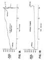
- In testing stabilizer materials, it seemed desirable to make the air bearing surface as smooth as possible. Glass, for example, was polished and lapped smooth with the expectation that the media would slide more easily over a smooth glass stabilizer. Then a diamond-like carbon material was coated on the glass air bearing surface and its leading edge to enhance hardness and smoothness. Current draw, as shown for the motor drive circuit by Figure 1A, nonetheless remained a significant problem. While the level of motor current might be acceptable at first (e.g., 296 mA at the beginning of a representative test run as illustrated by Figure 1A), continued operation required more and more current until the current requirement became excessive (e.g., about 590 mA after only 15 minutes). Indeed, the current draw as shown by Fig. 1A forced the circuit into uncontrolled saturation after 20 minutes, as indicated by the erratic current fluctuations in the region A.
- From "Chemical Abstracts", Vol. 89, 1978, page 234, abstract 79091Z, barium titanate is known as a material for preparing sliders for magnetic recording heads. In this material voids appeared near the surface in the size of 25µm to 800µm. This was however found disadvantageous so that these voids should be eliminated.
- In "Encyclopedia of Chemical Technology", Third Edition, Vol. 5, 1979, pages 299, 301, 308, electronic conduction in ceramics due to impurities is described.
- It can be found that, among many others, barium titanate can be made somewhat conductive. However, there was no limit that this could improve stabilizer operation.
-
Claim 1 specifies the invention. - The solution appeared elusive until barium titanate was used as a stabilizer material. Barium titanate, which is a ceramic material, was initially selected for its density and hardness. This ceramic material was found to be useful in the interface for longer periods than any other tested material without significantly increasing drag, and, as a result, without significantly increasing current draw upon the motor. (In Figure 1B, which is scaled comparably to Fig. 1A, the motor current experienced with a barium titanate stabilizer does not exceed 204 ma over a similar period). Though a solution was in hand, the reasons remained elusive. The properties that allow such low drag operation are best understood at this time to be related not at all to smoothness, as earlier expected, but to some combination of porosity, surface roughness and conductivity. (Hardness and density of the material may still play a beneficial role). The conductivity of the stabilizer is apparently helpful in reducing drag by reducing the accumulation of static electrical charge and the resultant static "cling" between the stabilizer and the media.
- Porosity is closely related to surface roughness as it defines an uneven, irregular surface with hills and valleys. Though the media and the stabilizer are in substantial contact, porosity and roughness are believed to create a turbulent airflow in or near the narrow channel between the media and the stabilizer. Increased turbulence apparently reduces drag by acting to "lubricate" the interface, allowing the media to slide by the stabilizer with less torque upon the motor. (In addition, the lubricant incorporated in the media may play some part.) It is further believed, though not experimentally verified at this time, that other materials (especially other ceramic materials of the titanate family, e.g., calcium titanate) with the requisite surface characteristics will perform as well as the tested barium titanate material.
- The prior art and the invention will be described in relation to the drawings, in which:
- Figures 1A and 1B are charts showing current draw on the drive motor for a coated glass stabilizer (prior art) and a ceramic stabilizer formed of barium titanate in accordance with the invention;
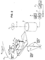
- Figure 2 is a perspective view of a stabilizer exhibiting low drag according to the invention and arranged at a negative attack angle in relation to a moving medium;
- Figure 3 is a plan view of the stabilizer of Figure 2, as seen through the medium;
- Figure 4 is a cross-sectional view of the stabilizer of Figure 2, showing in particular its penetration into the nominal plane of the moving medium;
- Figures 5A and 5B are detailed views of a leading edge portion of the stabilizer of Figure 4, one showing the interface between the medium and the stabilizer and the other showing the angular configuration of the leading edge; and
- Figure 6 is a plan view similar to Figure 3 but of a stabilizer that supports a dual-track thin film head.
- The invention will be described in relation to a stabilizer device supporting a transducer and to their mutual cooperation with a moving storage medium in order to establish an effective interface for mutual coupling of a signal. A drive unit for moving the medium is conventional and will not be described in detail. The preferred embodiment will be described in relation to a magnetic transducer and a magnetic storage medium such as a magnetic disk. While the description is directed generally to a magnetic disk, it should be understood that the disk can be one that is permanently emplaced in the drive unit, or one that is removable from the drive unit, and furthermore that a removable disk can be a self-contained unit or contained within a conventional cartridge jacket having openings for access to the disk.
- Details of the stabilizer device are shown by Figures 2, 3 and 4. A magnetic disk 10 (shown in broken line in Figures 2 and 3 so as to reveal underlying structure) is mounted for rotation by a
drive motor 12. Themotor 12 has aspindle 13 connecting to a hub 14 that is securely attached to an inside periphery of thedisk 10. Current for themotor 12 is supplied by adrive circuit 15, which is connected to apower supply 16. For example, themotor 12 may be a brushless dc motor and thedrive circuit 15 would provide electronic commutation of the motor. Feedback from a tachometer or like reference signal generator is provided to aspeed controller circuit 17 for controlling the speed of themotor 12. - A
stabilizer device 18 includes a stabilizingblock 20 having anopening 22 for exposing amagnetic head 24 to the surface of thedisk 10. A circumferential, substantially flatair bearing surface 26 surrounds theopening 22 on the side of theblock 20 that faces thedisk 10. Theblock 20 is, according to the invention, made of a hard ceramic material having a moderate degree of surface roughness and a relatively high conductivity. The preferred material for theblock 20 is a conductive barium titanate (BaTiO₃) available from Kyocera Corporation (Kyoto, Japan) as material item number T793H. The particular barium titanate material used was manufactured in a hot isostatic pressing (HIP) process. The resistivity of the preferred barium titanate is 1.2 x 10⁵ Ω-cm. Based on this data, it is postulated that resistivities on the order of 10⁶ Ω-cm or less provide sufficient conductivity to enhance the effect of the invention. The property of surface roughness of the preferred barium titanate material, and of the material of the prior art (glass with a diamond-like carbon (DLC) coating), was characterized by conventional root-mean-square measurement of surface height with a phase-shift interference microscope. The following root-mean-square figures (i.e., standard deviations) were obtained in micrometer (µm) or Angstroms (Å) from measurement of theair bearing surface 26 for a stabilizer made of each material:
BaTiO₃ glass w/DLC
0,0013µm(13Å) 0,0007µm(7Å)
It is believed from these measurements that a surface roughness of greater than about 0,001µm (10Å) is characteristic of a material that will regularly perform in accordance with the invention. (Since several other properties, e.g., conductivity, may interact with surface roughness to reduce current draw upon the motor, it is not possible to positively conclude that every material having a surface roughness of less than 0,001µm (10Å) will not have some beneficial effect on motor torque.) The surface height measurements can be made with, for example, a phase-shift interference microscope of the type manufactured by Wyco Corporation, Tucson, Arizona or a Normarski microscope profilometer manufactured by photographic Sciences Corporation, Rochester, New York. It can also be appreciated that porosity at a microscopic level in a hard material, such as a ceramic material, tends to ensure a certain level of surface roughness even after lapping and finishing of theair bearing surface 26. With porous material, such lapping only exposes further, different areas of porosity. Even if the media is worn smooth, the stabilizer remains porous and the turbulence in the interface will remain. Though thecircumferential surface 26 is shown to be oval in shape, other shapes are also believed to work in the practice of the invention. As best shown by Figure 3, the stabilizer device is used in a system in which thehead 24 traces acircular track 25 during recording and repeatedly traces thesame track 25 during reproduction. Each track can correspond, for example, to a single video picture (e.g., a video field) in a still video recording/reproduction system. - A best shown by Figure 4, the
opening 22 leads to acavity 23 in theblock 20. Anon-magnetic potting compound 28, such as epoxy, supports ashoe 30 within thecavity 23 in relation to the stabilizingblock 20. Thehead 24 is mounted on theshoe 30 to locate amagnetic gap 32 in relation to theopening 22 to that thegap 32 slightly protrudes above the plane of theair bearing surface 26. (Figure 4 also shows a modification in which a step 22' is recessed about 0,125mm (0.005 inches) below theair bearing surface 26 toward the edge of theopening 22. This step is believed to assist in the generation of coupling forces between themedia 10 and thehead 24, as well as acting to at least somewhat reduce motor drive current requirements.) The stabilizingblock 20 is supported with respect to thedisk 10 along a flatinclined surface 33 of the a wedge-shaped support 34 (or any other kind of like support) mounted upon a conventional head positioning carriage (not shown). As shown by Figure 2, thesupport 34 and thehead 24 therewith are disposed at a particular angle (the attack angle) with respect to magnetic track movement and at a further particular angle (the tilt angle) with respect to a radial of thedisk 10. While the precise dimensions of the stabilizer are not critical and may vary depending upon the size of the disk, head structure, etc., the particular dimensions used in connection with the single (or dual, as will be described in connection with Figure 6) track head for recording fifty circular tracks on a disk 47 mm in diameter include (referring to Figure 3) an approximate length L of 8,75 mm (0.350 inches) 8,2 mm (0.328 inches)(for dual track application) and width W of 6,25 mm (0.250 inches). - When the
magnetic disk 10 is rapidly rotated by thedrive motor 12 in a direction shown by anarrow 36, successive portions of thedisk 10 are in substantial contact with a leadingcurved edge 38 of the flatair bearing surface 26. (The term "substantial contact", as here used, allows for a narrow channel between the media and stabilizer device which is believed to permit the passage of a thin film of air.) the angle of the wedge-shapedsupport 34, which defines the attack angle, limits penetration of the leadingcurved edge 38 into anominal plane 40 of thedisk 10. (The nominal plane is the plane established by the rotating disk absent any interference.) The extent of penetration is generally quite small, e.g., 0,15 mm (0.006 in.). Preferably the attack angle should be as small as possible to prevent excessive wear of the transducer and/or media surfaces. In the preferred embodiment, theair bearing surface 26 is disposed at a negative angle of attack of 2.0° and at a tilt angle of 0°. - As shown by Figure 5B, a
portion 38a of the leadingedge 38 is defined by a radius r (r = 0,3 mm (0.012 in.) according to the preferred embodiment) up to a certain point P, where the smoothly varyingsurface 38a abruptly meets the flatair bearing surface 26 in a non-tangential transition. The edge-tracing radius r meets theair bearing surface 26 at an includedangle 42 that is acute. As further shown by broken line in Figure 5B, if the radius r is allowed to further trace a surface to point P', the joinder with the flat surface 26' (parallel to surface 26) would be in tangential relation, that is, the line defined by the surface 26' would be tangent to the circle described by radius r. When the leadingedge 38 is subjected to an abrupt transition at the point P, it can be seen that theair bearing surface 26 coincides with a chord PQ of the circle defined by the radius r. In the preferred embodiment, the perpendicular distance d of this chord PQ from the broken line surface 26' is between 0,0125 and 0,0375 mm (0.0005 and 0.0015 inches). - A stabilizer with the non-tangential transition P may be manufactured in any number of conventional ways. One way that works especially well is to manufacture a stabilizer of the type with a continuation of the blended
radius leading edge 38a', as shown in Figure 5B, leading into the surface 26'. Then the surface 26' is lapped by conventional techniques until the lapped surface coincides with theair bearing surface 26 shown in Figure 5B. This requires removal of a thickness corresponding to the distance d, that is, between 0,0125 and 0,0375 mm (0.0005 and 0.0015 inch). - As better shown by Figure 3, the transition point P is one of many points defining a
curved line 44 that first meets the surface of thedisk 10 as it is rotated over the penetrating leadingedge 38 of thestabilizer 18. Thecurved line 44, again shown as a point P in Figure 5A, serves as a fulcrum about which the contacting section of thedisk 10 attempts to rotate. Though the precise mechanism is not well established, it it believed that a torque force is generated according to an arrow 46 (Figure 5A) that attempts to twist thedisk 10 clockwise over thecurved edge 38. This force serves to deflect thedisk 10 from itsnominal plane 40 firmly upon theair bearing surface 26 despite any irregularities such as warps. In addition, it is believed that the leadingedge 38 operates as an "air scraper" to choke off the flow of moving air over theair bearing surface 26, thereby forming a Bernoulli pull down force across the surface, which also helps to deflect thedisk 10 from itsnominal plane 40.
Futhermore, as successive portions of thedisk 10 move over theopening 22 and itsunderlying cavity 23, air will be removed from the cavity, causing the formation of a negative low pressure in the cavity. The negative pressure generates a pull down force on successive portions of the rotateddisk 10 as each portion is moved across the opening, which further deflects thedisk 10 into contact with thetransducer gap 32 of thehead 24. - The net interaction of all of these forces generates a sufficient coupling force for the stabilization of the magnetic interface even for media possessing significant warps or other deformations. Despite stabilization of the interface, however, the aforementioned drag is experienced with conventionally-prepared stabilizers. As shown by Figure 1A, current draw on the motor steadily increases over operational time when a stabilizer made of glass coated with diamond-like carbon (DLC) is used in establishing the head-media interface. Figure 1B, on the other hand, shows the relatively constant current draw over the same time for a stabilizer formed of barium titanate (BaTiO). It is hypothesized that the surface porosity and roughness of the
air bearing surface 26 formed of barium titanate generates a microscopic turbulence in a narrow channel between thesurface 26 and the movingmedium 10. The turbulence is enough to effect a "lubrication" of the two surfaces without disturbing the coupling forces that act upon the media. The surface conductivity apparently plays a part, which is not completely understood at this time, in reducing frictional drag. For instance, the higher surface resistance of glass with DLC coating (approximately 10¹⁰ Ω-cm) apparently encourages the build-up of static charge as compared to the relatively more conductive barium titanate (1.2 x 10⁵ Ω-cm). - As shown by Figure 6, the preferred stabilizer may have an opening 50 large enough (without substantially changing the external dimensions L and W) to accommodate a
dual gap head 52 for tracing twotracks film head 52 rather than a wound ferrite head. In the case of a dual-gap stabilizer, it has been found that somewhat better pull-down performance is obtained by having the epoxy 28 completely seal one end of the cavity 23 (see Figure 4). Conversely, such a complete seal is unnecessary for a single-gap stabilizer; indeed, vents are provided through the epoxy 28 if it should happen to seal thecavity 23. - Furthermore, while the stabilizer device has been disclosed as being homogeneous in regard to its composition (e.g., BaTiO₃), it is not inconceivable that a hard coating could be applied to the air bearing surface especially if such a coating takes on the surface aspect of the underlying material.
Claims (3)
- A stabilizer device for stabilizing the movement of a storage medium (10) advanced in a predetermined direction in relation to a transducer (24), the stabilizer device including a stabilizing block (20) having a cavity (23) in which the transducer (24) is supported, a circumferential air bearing surface (26) around said cavity (23) on the side of said stabilizing block facing the medium (10), a curved edge (38) on at least the side of said circumferential surface (26) that faces the advancing storage medium (10), and support means (33, 34) for disposing said stabilizing block (20) at an angle with respect to the nominal plane (40) of the storage medium (10);
said device being characterized in that said stabilizing block (20) is of conductive ceramic material and that said circumferential air bearing surface (26) has a RMS surface roughness in the range of 0.001µm to 25µm, the surface of said advancing storage medium (10) thereby interacting with said roughened, conductive air bearing surface (26) to minimize drag between the surfaces due to mechanical and electrical sources. - A stabilizer device as claimed in Claim 1 in which the stabilizing block (20) is made of a conductive barium titanate.
- A stabilizer device as claimed in Claims 1 or 2 in which the resistivity of said ceramic stabilizing block (20) is less than about 10⁶ Ω-cm.
Applications Claiming Priority (2)
| Application Number | Priority Date | Filing Date | Title |
|---|---|---|---|
| US136793 | 1987-12-22 | ||
| US07/136,793 US4833556A (en) | 1987-12-22 | 1987-12-22 | Low drag stabilizer device for stabilizing the interface between a transducer and a moving medium |
Publications (2)
| Publication Number | Publication Date |
|---|---|
| EP0346439A1 EP0346439A1 (en) | 1989-12-20 |
| EP0346439B1 true EP0346439B1 (en) | 1993-07-07 |
Family
ID=22474387
Family Applications (1)
| Application Number | Title | Priority Date | Filing Date |
|---|---|---|---|
| EP89901174A Expired - Lifetime EP0346439B1 (en) | 1987-12-22 | 1988-12-19 | Low drag stabilizer device for stabilizing the interface between a transducer and a moving medium |
Country Status (5)
| Country | Link |
|---|---|
| US (1) | US4833556A (en) |
| EP (1) | EP0346439B1 (en) |
| JP (1) | JPH02502682A (en) |
| DE (1) | DE3882224T2 (en) |
| WO (1) | WO1989006035A1 (en) |
Families Citing this family (22)
| Publication number | Priority date | Publication date | Assignee | Title |
|---|---|---|---|---|
| US4945436A (en) * | 1987-07-27 | 1990-07-31 | Fuji Photo Film Co., Ltd. | Double-sided recording method using slanted guide plates upstream and downstream of recording heads |
| JPH01146163A (en) * | 1987-12-02 | 1989-06-08 | Copal Co Ltd | Magnetic disk driving device |
| JPH0719459B2 (en) * | 1987-12-03 | 1995-03-06 | 日立金属株式会社 | Floating magnetic head |
| US5162962A (en) * | 1988-03-29 | 1992-11-10 | Kao Corporation | Magnetic recording apparatus having reduced friction sliding parts |
| JPH0256765A (en) * | 1988-08-23 | 1990-02-26 | Alps Electric Co Ltd | Magnetic head supporting device |
| US5010429A (en) * | 1988-11-22 | 1991-04-23 | Hitachi Metals, Ltd. | Floating magnetic head having improved static friction coefficient |
| US5047884A (en) * | 1989-01-17 | 1991-09-10 | Fuji Photo Film Co., Ltd. | Magnetic head having a control portion for generating negative pressure |
| US5717551A (en) * | 1989-01-17 | 1998-02-10 | Fuji Photo Film Co., Ltd. | Contact-type magnetic head having an integral control portion for generating negative pressure |
| US5138509A (en) * | 1989-03-14 | 1992-08-11 | Fuji Photo Film Co., Ltd. | Negative pressure control member for stabilizing magnetic disk contact with a magnetic head |
| US4975794A (en) * | 1989-03-27 | 1990-12-04 | Iomega Corporation | Bernoulli effect transducer coupler |
| DE69032039T2 (en) * | 1989-11-07 | 1998-06-18 | Canon Kk | Recording or playback device |
| US6600631B1 (en) | 1989-11-27 | 2003-07-29 | Censtor Corp. | Transducer/flexure/conductor structure for electromagnetic read/write system |
| DE69222791T2 (en) * | 1991-03-04 | 1998-03-12 | Canon Kk | Recording or playback device and head-supporting device |
| EP0576680B1 (en) * | 1992-01-20 | 2004-03-31 | Fujitsu Limited | Magnetic head assembly, its manufacture, and magnetic disc device |
| EP0571300A1 (en) * | 1992-05-19 | 1993-11-24 | Eastman Kodak Company | Magnetic record/reproduce head having improved service life, and new material therefor |
| US5646806A (en) * | 1994-02-09 | 1997-07-08 | Minnesota Mining And Manufacturing Company | Edge tensioning sloping tape guide for arcuately scanning tape drive |
| WO1997048095A1 (en) | 1996-06-12 | 1997-12-18 | Imation Corp. | Bernouilly type flexible media stabilization for laser servowriting |
| US7153366B1 (en) * | 1998-03-24 | 2006-12-26 | Quantum Corporation | Systems and method for forming a servo pattern on a magnetic tape |
| US6346807B1 (en) * | 1999-10-22 | 2002-02-12 | Bently Nevada Corporation | Digital eddy current proximity system: apparatus and method |
| US20040040652A1 (en) * | 2002-08-30 | 2004-03-04 | 3M Innovative Properties Company | Methods for electrostatically adhering an article to a substrate |
| US7187515B2 (en) * | 2003-02-05 | 2007-03-06 | Quantum Corporation | Method and system for tracking magnetic media with embedded optical servo tracks |
| US6980390B2 (en) | 2003-02-05 | 2005-12-27 | Quantum Corporation | Magnetic media with embedded optical servo tracks |
Family Cites Families (21)
| Publication number | Priority date | Publication date | Assignee | Title |
|---|---|---|---|---|
| FR2075466A5 (en) * | 1970-01-29 | 1971-10-08 | Ibm | |
| US3821813A (en) * | 1972-12-27 | 1974-06-28 | Ibm | Wasp waist head for flying flexible magnetic storage medium over head |
| US4003091A (en) * | 1976-03-08 | 1977-01-11 | International Business Machines Corporation | Transducer support and stabilizer |
| US4151573A (en) * | 1977-06-13 | 1979-04-24 | Tandon Magnetics Corp. | Magnetic recording device for double sided media |
| JPS5423517A (en) * | 1977-07-25 | 1979-02-22 | Nippon Telegr & Teleph Corp <Ntt> | Floating head slider |
| JPS54143217A (en) * | 1978-04-28 | 1979-11-08 | Tdk Corp | Magnetic head |
| US4396965A (en) * | 1979-08-06 | 1983-08-02 | Burroughs Corporation | Flying head with foil support |
| JPS5683869A (en) * | 1979-12-10 | 1981-07-08 | Fujitsu Ltd | Structure of thin film magnetic head |
| US4379315A (en) * | 1980-10-21 | 1983-04-05 | Applied Magnetics Corporation | Carriage loading arm assembly having two magnetic transducers for a double sided floppy disc |
| JPS57105824A (en) * | 1980-12-23 | 1982-07-01 | Nec Corp | Head for magnetic disc |
| US4376960A (en) * | 1980-12-31 | 1983-03-15 | International Business Machines Corporation | Flexible disk stabilizing structure |
| US4414592A (en) * | 1981-05-01 | 1983-11-08 | Iomega Corporation | Support for stabilizing the movement of a magnetic medium over a magnetic head |
| JPS5859147A (en) * | 1981-09-29 | 1983-04-08 | Fuji Photo Film Co Ltd | Belt-shaped material conveying ceramic guide and its manufacture |
| JP2666924B2 (en) * | 1983-04-18 | 1997-10-22 | 株式会社東芝 | Magnetic disk device |
| JPS59229767A (en) * | 1983-06-10 | 1984-12-24 | Sony Corp | Rotary sliding member of magnetic recording and reproducing device |
| US4578727A (en) * | 1984-02-27 | 1986-03-25 | Eastman Kodak Company | Device for stabilizing the movement of a floppy disk over a magnetic head |
| US4620250A (en) * | 1984-03-29 | 1986-10-28 | Eastman Kodak Company | Transducer-to-medium stabilizing device at negative attack angle with respect to medium |
| CA1265867A (en) * | 1984-11-13 | 1990-02-13 | Raju S. Ananth | Slider with anti-stiction boss |
| JPS6243819A (en) * | 1985-08-22 | 1987-02-25 | Tdk Corp | Magnetic recording medium |
| US4792874A (en) * | 1987-02-26 | 1988-12-20 | Eastman Kodak Company | Stabilizer device having an edge configuration for stabilizing the interface between a transducer and a moving medium |
| JPH06214317A (en) * | 1993-01-19 | 1994-08-05 | Ricoh Co Ltd | Optical system dustproof device for image forming device |
-
1987
- 1987-12-22 US US07/136,793 patent/US4833556A/en not_active Expired - Fee Related
-
1988
- 1988-12-19 WO PCT/US1988/004654 patent/WO1989006035A1/en not_active Ceased
- 1988-12-19 EP EP89901174A patent/EP0346439B1/en not_active Expired - Lifetime
- 1988-12-19 DE DE89901174T patent/DE3882224T2/en not_active Expired - Fee Related
- 1988-12-19 JP JP1501117A patent/JPH02502682A/en active Pending
Also Published As
| Publication number | Publication date |
|---|---|
| DE3882224T2 (en) | 1994-02-03 |
| JPH02502682A (en) | 1990-08-23 |
| WO1989006035A1 (en) | 1989-06-29 |
| DE3882224D1 (en) | 1993-08-12 |
| US4833556A (en) | 1989-05-23 |
| EP0346439A1 (en) | 1989-12-20 |
Similar Documents
| Publication | Publication Date | Title |
|---|---|---|
| EP0346439B1 (en) | Low drag stabilizer device for stabilizing the interface between a transducer and a moving medium | |
| JP3718524B2 (en) | Arcuate scanning tape drive | |
| US7481697B2 (en) | Head slider and method of manufacturing same | |
| US7630166B2 (en) | Control flow instability to reduce disk flutter and half frequency whirl | |
| US6185071B1 (en) | Head slider having streamlined pads | |
| EP0363468B1 (en) | Magnetic recording device using circumferentially offset heads with double sided media | |
| US4792874A (en) | Stabilizer device having an edge configuration for stabilizing the interface between a transducer and a moving medium | |
| JPH039174Y2 (en) | ||
| EP0381741A1 (en) | Double-sided magnetic recording device supporting two transducers in fixed relation. | |
| JP3478467B2 (en) | Method for applying conductive paint and method for producing magnetic recording medium | |
| JPH06150600A (en) | Floating type magnetic head | |
| JPH02287239A (en) | Apparatus for measuring static friction between magnetic disk and magnetic head | |
| JPH02121150A (en) | Rotary drum device | |
| JPH08180339A (en) | Magnetic head device | |
| JP2558650B2 (en) | Magnetic disk device | |
| JPH08321100A (en) | Magnetic recording and / or reproducing apparatus | |
| JPH0320900Y2 (en) | ||
| JPS62117165A (en) | Rotary magnetic sheet device | |
| JPS6275926A (en) | Slider for magnetic head | |
| JPH0554487A (en) | Rotary head assembly | |
| JPH07334897A (en) | Rotating head drum device | |
| JP2000090617A (en) | Magnetic head slider | |
| CN1168734A (en) | Tape Support System for Arc Scanning Rotary Heads | |
| JPS59154664A (en) | Rotary drum for magnetic head of magnetic recording and reproducing device | |
| JPH03154258A (en) | Rotary magnetic head device |
Legal Events
| Date | Code | Title | Description |
|---|---|---|---|
| PUAI | Public reference made under article 153(3) epc to a published international application that has entered the european phase |
Free format text: ORIGINAL CODE: 0009012 |
|
| AK | Designated contracting states |
Kind code of ref document: A1 Designated state(s): BE DE FR GB NL |
|
| 17P | Request for examination filed |
Effective date: 19891204 |
|
| 17Q | First examination report despatched |
Effective date: 19920529 |
|
| GRAA | (expected) grant |
Free format text: ORIGINAL CODE: 0009210 |
|
| AK | Designated contracting states |
Kind code of ref document: B1 Designated state(s): BE DE FR GB NL |
|
| PG25 | Lapsed in a contracting state [announced via postgrant information from national office to epo] |
Ref country code: NL Effective date: 19930707 Ref country code: BE Effective date: 19930707 |
|
| REF | Corresponds to: |
Ref document number: 3882224 Country of ref document: DE Date of ref document: 19930812 |
|
| ET | Fr: translation filed | ||
| PGFP | Annual fee paid to national office [announced via postgrant information from national office to epo] |
Ref country code: GB Payment date: 19931118 Year of fee payment: 6 |
|
| PGFP | Annual fee paid to national office [announced via postgrant information from national office to epo] |
Ref country code: DE Payment date: 19931214 Year of fee payment: 6 |
|
| PGFP | Annual fee paid to national office [announced via postgrant information from national office to epo] |
Ref country code: FR Payment date: 19931215 Year of fee payment: 6 |
|
| NLV1 | Nl: lapsed or annulled due to failure to fulfill the requirements of art. 29p and 29m of the patents act | ||
| PLBE | No opposition filed within time limit |
Free format text: ORIGINAL CODE: 0009261 |
|
| STAA | Information on the status of an ep patent application or granted ep patent |
Free format text: STATUS: NO OPPOSITION FILED WITHIN TIME LIMIT |
|
| 26N | No opposition filed | ||
| PG25 | Lapsed in a contracting state [announced via postgrant information from national office to epo] |
Ref country code: GB Effective date: 19941219 |
|
| GBPC | Gb: european patent ceased through non-payment of renewal fee |
Effective date: 19941219 |
|
| PG25 | Lapsed in a contracting state [announced via postgrant information from national office to epo] |
Ref country code: FR Effective date: 19950831 |
|
| PG25 | Lapsed in a contracting state [announced via postgrant information from national office to epo] |
Ref country code: DE Effective date: 19950901 |
|
| REG | Reference to a national code |
Ref country code: FR Ref legal event code: ST |