EP0346081A1 - Blaskasten für Luftkissen - Google Patents
Blaskasten für Luftkissen Download PDFInfo
- Publication number
- EP0346081A1 EP0346081A1 EP89305719A EP89305719A EP0346081A1 EP 0346081 A1 EP0346081 A1 EP 0346081A1 EP 89305719 A EP89305719 A EP 89305719A EP 89305719 A EP89305719 A EP 89305719A EP 0346081 A1 EP0346081 A1 EP 0346081A1
- Authority
- EP
- European Patent Office
- Prior art keywords
- air
- web
- bar
- lamp
- channel
- Prior art date
- Legal status (The legal status is an assumption and is not a legal conclusion. Google has not performed a legal analysis and makes no representation as to the accuracy of the status listed.)
- Granted
Links
Images


Classifications
-
- F—MECHANICAL ENGINEERING; LIGHTING; HEATING; WEAPONS; BLASTING
- F26—DRYING
- F26B—DRYING SOLID MATERIALS OR OBJECTS BY REMOVING LIQUID THEREFROM
- F26B13/00—Machines and apparatus for drying fabrics, fibres, yarns, or other materials in long lengths, with progressive movement
- F26B13/10—Arrangements for feeding, heating or supporting materials; Controlling movement, tension or position of materials
- F26B13/101—Supporting materials without tension, e.g. on or between foraminous belts
- F26B13/104—Supporting materials without tension, e.g. on or between foraminous belts supported by fluid jets only; Fluid blowing arrangements for flotation dryers, e.g. coanda nozzles
-
- F—MECHANICAL ENGINEERING; LIGHTING; HEATING; WEAPONS; BLASTING
- F26—DRYING
- F26B—DRYING SOLID MATERIALS OR OBJECTS BY REMOVING LIQUID THEREFROM
- F26B3/00—Drying solid materials or objects by processes involving the application of heat
- F26B3/28—Drying solid materials or objects by processes involving the application of heat by radiation, e.g. from the sun
- F26B3/283—Drying solid materials or objects by processes involving the application of heat by radiation, e.g. from the sun in combination with convection
Definitions
- the present invention overcomes the disadvantages of the prior art dryers by providing an electromagnetically radiating air float bar to replace existing air float bars in web dryers.
- the energy emitting lamp In addition to air flow of dry air from the web-supporting air flow slots at the upper and outer extremities of the air float bar, transmits electromagnetic radiation to the traversing web.
- the drying of the traversing web is accomplished by impingement of a combination of both heated web-supporting air flow and electromagnetic radiation.
- the combined concentration of heat from the web-supporting air flow and the electromagnetic radiation from the lamp is of a sufficient magnitude to allow the web to dry at a higher speed than normal prior art speed.
- the present invention thus provides an air float bar having a radiant lamp for the generation and transmission of ultra-violet electromagnetic radiation by itself or in combination with a heated web-supporting air flow upon a web traversing through the dryer.
- the lamp is located between the slots for the web discharging air flow and at the point of highest heat transfer, namely between the air flow slots.
- Ultra-violet or infra-red electromagnetic energy may pass in a straightforward, direct manner through the lens to impinge upon a traversing web, but may also be reflected in an indirect manner from a reflector surface (where present) and through the same lens to impinge upon the traversing web.
- An air supply duct may introduce cooling air into an enclosed terminal chamber and about the area containing the lamp, and overboard through an opposing enclosed terminal area.
- an air bar header member provides the framework for support and includes V or like channels on each side for the inclusion of an internal diffusion plate. Lips on the upper portion of the air bar header form one edge of air outlet slots, which may optionally use the Coanda effect, and a fixed position channel member forms the other portion of the slots. In that case the fixed position channel member includes Coanda curves.
- a removable channel fits inside a fixed position channel and contains the lamp, a reflector and a lens element.
- An enclosed terminal box juxtaposes with each end of the removable channel member containing the lamp, the reflector, and the lens element.
- a cooling air supply duct placed in close proximity with one enclosed terminal box supplies cooling air which flows through the enclosed terminal chamber, through the area surrounding the lamp, through an opposing enclosed terminal chamber and finally through an exhaust air duct channel.
- Oval air supply inlets on the bottom of the air bar header provide air flow for the web-supporting air slots.
- the air float bar of the present invention offers an increased heat transfer rate per unit size of the air bar which is a practical alternative solution to increasing production requirements.
- the air float bar of the present invention can be used to dry products that require high controlled heat and non-contact support.
- This air float bar can be used in curing of pre-impregnated products such as polymer coatings that require airing, and are affected by high air impingement rates.
- the air float bar can also be used for drying of low solids coatings, and water-based coatings that are sensitive to high air impingement during the first stages of drying process.
- the air float bar can also be used for drying water based coatings on steel strip webs which require high controlled heat loads. Because of the ability to switch the lamp on or off almost instantly, the air bars can be run with cold convection air for support, and the lamp can be used as the only heat source so that the bar is useful for drying webs that cannot endure high temperatures and that experience frequent web stops.
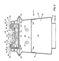
- FIG 1 illustrates a perspective view of an air float bar 10 of the present invention, for use in drying a web in a web dryer.
- Externally visible members of the air float bar 10 include a channel-like air bar header 12 with opposing sides 14 and 16, a bottom 18, and opposing and parallel vertically aligned air bar end plates 20 and 22 affixed between sides 14 and 16.
- V channels 24 and 26 are formed and aligned horizontally in sides 14 and 16 to accommodate an air bar mounting flange as later described in detail.
- V channel 26 is illustrated in Figure 2.
- a fixed air bar channel 28 aligns longitudinally in a precise manner between the upper regions of sides 14 and 16 to provide for forming longitudinally aligned and uniformly sized Coanda slots 30 and 32 for web-supporting air as later described in detail.
- a second removable channel 34 including an ultra-violet lamp 36 and a quartz lens 38, is accommodated in a sliding fashion by the fixed air bar channel 28.
- Air supply ducts 40 and 50 fit adjacent to covered terminal chambers 42 and 44 at each end of the removable channel 34 of the air float bar 10 and provides cooling air for the ultra-violet lamp 36.
- the cooling air passes through the air supply ducts 40 and 50, through the covered terminal chambers 42 and 44, into the removable channel 34, thus cooling the ultra-violet lamp 36, and leaks out of the ultra-violet lamp chamber through the clearance provided between the quartz lens 38 and the cover plates 46 and 48 for the terminal chambers 42 and 44.
- the covered terminal chamber 42 includes a cover plate 46, and covered terminal chamber 44 includes a cover plate 48.
- the covered terminal chamber 44 is secured above the air duct channel 50. Solvent-laden air is kept from the interior of the chamber in which the ultra-violet lamp resides by pressurization of the covered terminal chambers 42 and 44 and the area therebetween.
- a plurality of oval-shaped air inlets 52a-52n positioned on the bottom surface 18 of the air bar header 12 serves to supply drying air through the air bar header 12 to the Coanda slots 30 and 32.
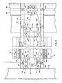
- Figure 2 illustrates a cross-sectional view of the air float bar 10 taken along line 2-2 of Figure 1; all numerals correspond to those elements previously described.
- the removable channel 34 and the ultra-violet lamp 36 are accommodated by the fixed air bar channel 28.
- a diffuser plate 54 with a plurality of holes 56a-56n secured between sides 14 and 16 serves to provide for even flow of drying air from the plurality of oval-shaped air inlets 52a-52n.
- a support plate 60 positioned between V channels 24 and 26 includes a plurality of holes 62a-62n.
- a plurality of holes 64a-64n align longitudinally in two rows along the support plate 60.
- the bottom 18, sides 14 and 16, and the diffuser plate 54 define a first chamber 66.
- the diffuser plate 54, sides 14 and 16, and the support plate 60 define a second chamber 68.
- the fixed air bar channel 28 is secured by welding or other suitable attachment to the support plate 60, and includes sides 70 and 72, Coanda curves 74 and 76, and horizontal planar surfaces 78 and 80 at right angles to sides 70 and 72.
- Lips 82 and 84, as extensions of sides 16 and 14, extend inwardly at right angles to form Coanda slots 30 and 32 between the ends of lips 82 and 84 and Coanda curves 74 and 76, respectively, each slot being of a finite size.
- Chamber 86 is formed by the fixed air bar channel side 70, the outer portion of support plate 60, the upper portion of side 16, and the lip 82.
- chamber 88 is formed by the fixed air bar channel side 72, the outer portion of support plate 60, the upper portion of side 14, and the lip 84.
- the area between the Coanda slots 30 and 32, known as the pressure pad 89, includes the quartz lens 38, the ultra-violet lamp 36, and the reflector 100.
- Removable channel 34 is illustrated inserted within the fixed air bar channel 28.
- the quartz lens 38 which can also be manufactured of other material, is essentially rectangular in shape and includes shoulders 90 and 92 which correspondingly engage beneath ends 94 and 96 of the removable channel 34.
- a trough-like reflector 100 is illustrated as parabolic, but may also be any other desired geometrical shape and may be fashioned of a suitable material such as stainless steel, aluminium, or other reflective material.
- the reflector 100 includes planar feet 102 and 104 along the edge of the reflector 100 and a curved portion 106 therebetween. The curved portion 106 of the reflector 100 is positioned against the bottom member 34a of the removable channel 34.
- the planar feet 102 and 104 spring against the quartz lens 38 to ensure engagement of the shoulders 90 and 92 of the quartz lens 38 against the end portions 94 and 96 of the removable channel 34.
- Rectangular Teflon terminal mounting blocks 110 and 112 for mounting of the ultra-violet lamp 36 and related components, are secured to a mounting plate 114 with machine screws 116 and 118.
- Opposing sides 120 and 122 of a clip style mounting bracket 124 engage over the flat ultra-violet lamp end terminal 126 as machine screws 128 and 130 bring tension to bear upon the clip-style mounting bracket 124. While a single ultra-violet lamp 36 is illustrated, a plurality of lamps mounted in a parallel fashion can be used for applications requiring yet even more ultra-violet magnetic radiation. Larger air float bar assemblies can include multiple parallel ultra-violet lamps to transmit ultra-violet electromagnetic radiation to a traversing web.
- the air duct channel 50 is secured to the underside of the covered terminal chamber 44.
- a bracket 152 secured to the bottom of the air duct channel 50 serves to provide support for the air duct channel 50 and associated components.
- a bracket 152 is secured to the framework 134 by machine screws 154 and 156.
- Teflon mounting blocks 160 and 162 similar to the Teflon mounting blocks 110 and 112 are secured to a mounting plate 164 with machine screws 166 and 168 as also illustrated in Figure 4.
- Opposing sides 170 and 172 of the clip style mounting bracket 174 engage over the flat ultra-violet lamp end terminal 175 as machine screws 176 and 178 bring tension to bear upon the clip style mounting bracket 174 as also illustrated in Figure 4.
- Another connector cap 200 is connected between the connector pad 194 with wire 202 to the opposing end terminal 126 of the ultra-violet lamp via the mounting bracket 124 as illustrated in Figure 4.
- the wires 198 and 202 pass through orifices 204 and 206 in the air duct channel 50 and through orifice 208 in the removable channel 34.
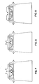
- cooling air can be channeled from the covered terminal chambers 42 and 44 to flow about the convex side of the reflector 100.
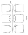
- Direct and indirect ultra-violet energy rays 216a-216n impinge on the web and heat the web 218 as it passes over the pressure pad 89, thus drying and evaporating solvents from the web 218. This, in combination with impinging air flows 220a-220n, maximizes the heat transfer in the area of the pressure pad 89.
- Output of the lamp 36 can be variably controlled, such as by an SCR, so that the amount of energy output transmitted from the lamp 36 can be chosen from a range extending from full power to no power.
Landscapes
- Engineering & Computer Science (AREA)
- Mechanical Engineering (AREA)
- General Engineering & Computer Science (AREA)
- Textile Engineering (AREA)
- Life Sciences & Earth Sciences (AREA)
- Microbiology (AREA)
- Drying Of Solid Materials (AREA)
Applications Claiming Priority (4)
| Application Number | Priority Date | Filing Date | Title |
|---|---|---|---|
| US07/203,138 US5035066A (en) | 1988-06-07 | 1988-06-07 | Ultraviolet air floatation bar |
| US203076 | 1988-06-07 | ||
| US07/203,076 US5092059A (en) | 1988-06-07 | 1988-06-07 | Infrared air float bar |
| US203138 | 1988-06-07 |
Publications (2)
| Publication Number | Publication Date |
|---|---|
| EP0346081A1 true EP0346081A1 (de) | 1989-12-13 |
| EP0346081B1 EP0346081B1 (de) | 1992-12-23 |
Family
ID=26898295
Family Applications (1)
| Application Number | Title | Priority Date | Filing Date |
|---|---|---|---|
| EP19890305719 Expired EP0346081B1 (de) | 1988-06-07 | 1989-06-07 | Blaskasten für Luftkissen |
Country Status (2)
| Country | Link |
|---|---|
| EP (1) | EP0346081B1 (de) |
| DE (1) | DE68903999T2 (de) |
Cited By (9)
| Publication number | Priority date | Publication date | Assignee | Title |
|---|---|---|---|---|
| GB2236584A (en) * | 1989-10-05 | 1991-04-10 | Spooner Ind Ltd | Air-float web treatment apparatus |
| EP0452867A1 (de) * | 1990-04-18 | 1991-10-23 | Van Brandwijk Systems Programming B.V. | Verfahren und Vorrichtung zur Wärmebehandlung einer mit einer flüssigen oder pastenförmigen Zubereitung versehenen Warenbahn |
| EP0507218A1 (de) * | 1991-04-04 | 1992-10-07 | J.M. Voith GmbH | Trockenpartie |
| EP0508253A1 (de) * | 1991-04-12 | 1992-10-14 | Van Brandwijk Systems Programming B.V. | Verfahren und Vorrichtung zur Wärmebehandlung einer mit einer flüssigen oder pastenförmigen Zubereitung versehenen Warenbahn |
| EP0508254A1 (de) * | 1991-04-12 | 1992-10-14 | Van Brandwijk Systems Programming B.V. | Verfahren und Vorrichtung zur Wärmebehandlung einer mit einer flüssigen oder pastenförmigen Zubereitung versehenen Warenbahn |
| EP0539013A1 (de) * | 1991-10-24 | 1993-04-28 | W.R. Grace & Co.-Conn. | Kombinierter Infrarot- und Schwebetrockner |
| WO1995010012A1 (fr) * | 1993-10-06 | 1995-04-13 | Infra Rouge System | Dispositif de deviation sans contact pour materiau en feuille |
| EP0743178A3 (de) * | 1994-11-17 | 1997-02-19 | Lts Trocknungsverfahren Gmbh | Leiteinrichtung für bedruckte Bogen und/oder Bahnen in Trocknersystemen |
| EP0916915A1 (de) * | 1997-11-14 | 1999-05-19 | Solaronics | Kombiniertes Konvektions-Strahlungssystem zur Wärmebehandlung einer kontinuierlichen Warenbahn |
Citations (8)
| Publication number | Priority date | Publication date | Assignee | Title |
|---|---|---|---|---|
| DE2112706A1 (de) * | 1970-03-19 | 1971-09-30 | Wiggins Teape Res Dev | Verfahren und Vorrichtung zum Trocknen von Materialbahnen |
| FR2247687A1 (de) * | 1973-10-12 | 1975-05-09 | Buettner Schilde Haas Ag | |
| FR2438613A1 (de) * | 1978-10-12 | 1980-05-09 | Grace W R Ltd | |
| US4501072A (en) * | 1983-07-11 | 1985-02-26 | Amjo, Inc. | Dryer and printed material and the like |
| US4594795A (en) * | 1984-10-23 | 1986-06-17 | Erik Stephansen | Air bearing support apparatus for drying a moving web |
| US4646446A (en) * | 1985-11-04 | 1987-03-03 | American Screen Printing Equipment Company | UV curing apparatus |
| WO1987005644A1 (en) * | 1986-03-14 | 1987-09-24 | Valmet Paper Machinery Inc. | Floater dryer and procedure for enhancing its operation |
| US4768695A (en) * | 1987-06-11 | 1988-09-06 | Advance Systems, Inc. | Air bar for paper web handling apparatus and having an air distributing chamber and perforated plate therefor |
-
1989
- 1989-06-07 DE DE1989603999 patent/DE68903999T2/de not_active Expired - Fee Related
- 1989-06-07 EP EP19890305719 patent/EP0346081B1/de not_active Expired
Patent Citations (8)
| Publication number | Priority date | Publication date | Assignee | Title |
|---|---|---|---|---|
| DE2112706A1 (de) * | 1970-03-19 | 1971-09-30 | Wiggins Teape Res Dev | Verfahren und Vorrichtung zum Trocknen von Materialbahnen |
| FR2247687A1 (de) * | 1973-10-12 | 1975-05-09 | Buettner Schilde Haas Ag | |
| FR2438613A1 (de) * | 1978-10-12 | 1980-05-09 | Grace W R Ltd | |
| US4501072A (en) * | 1983-07-11 | 1985-02-26 | Amjo, Inc. | Dryer and printed material and the like |
| US4594795A (en) * | 1984-10-23 | 1986-06-17 | Erik Stephansen | Air bearing support apparatus for drying a moving web |
| US4646446A (en) * | 1985-11-04 | 1987-03-03 | American Screen Printing Equipment Company | UV curing apparatus |
| WO1987005644A1 (en) * | 1986-03-14 | 1987-09-24 | Valmet Paper Machinery Inc. | Floater dryer and procedure for enhancing its operation |
| US4768695A (en) * | 1987-06-11 | 1988-09-06 | Advance Systems, Inc. | Air bar for paper web handling apparatus and having an air distributing chamber and perforated plate therefor |
Cited By (13)
| Publication number | Priority date | Publication date | Assignee | Title |
|---|---|---|---|---|
| GB2236584A (en) * | 1989-10-05 | 1991-04-10 | Spooner Ind Ltd | Air-float web treatment apparatus |
| US5299362A (en) * | 1990-04-18 | 1994-04-05 | Van Brandwijk Systems Programming B. V. | Method of, and apparatus for, heat treating a material web provided with a liquid or paste-like preparation |
| EP0452867A1 (de) * | 1990-04-18 | 1991-10-23 | Van Brandwijk Systems Programming B.V. | Verfahren und Vorrichtung zur Wärmebehandlung einer mit einer flüssigen oder pastenförmigen Zubereitung versehenen Warenbahn |
| EP0507218A1 (de) * | 1991-04-04 | 1992-10-07 | J.M. Voith GmbH | Trockenpartie |
| EP0508253A1 (de) * | 1991-04-12 | 1992-10-14 | Van Brandwijk Systems Programming B.V. | Verfahren und Vorrichtung zur Wärmebehandlung einer mit einer flüssigen oder pastenförmigen Zubereitung versehenen Warenbahn |
| EP0508254A1 (de) * | 1991-04-12 | 1992-10-14 | Van Brandwijk Systems Programming B.V. | Verfahren und Vorrichtung zur Wärmebehandlung einer mit einer flüssigen oder pastenförmigen Zubereitung versehenen Warenbahn |
| EP0539013A1 (de) * | 1991-10-24 | 1993-04-28 | W.R. Grace & Co.-Conn. | Kombinierter Infrarot- und Schwebetrockner |
| WO1995010012A1 (fr) * | 1993-10-06 | 1995-04-13 | Infra Rouge System | Dispositif de deviation sans contact pour materiau en feuille |
| FR2710971A1 (fr) * | 1993-10-06 | 1995-04-14 | Infra Rouge System | Dispositif de déviation sans contact pour matériau en feuille. |
| EP0743178A3 (de) * | 1994-11-17 | 1997-02-19 | Lts Trocknungsverfahren Gmbh | Leiteinrichtung für bedruckte Bogen und/oder Bahnen in Trocknersystemen |
| EP0916915A1 (de) * | 1997-11-14 | 1999-05-19 | Solaronics | Kombiniertes Konvektions-Strahlungssystem zur Wärmebehandlung einer kontinuierlichen Warenbahn |
| FR2771161A1 (fr) * | 1997-11-14 | 1999-05-21 | Solaronics | Systeme convecto-radiatif pour traitement thermique d'une bande continue |
| US6088930A (en) * | 1997-11-14 | 2000-07-18 | Solaronics Process Sa | Convection-radiation system for heat treatment of a continuous strip |
Also Published As
| Publication number | Publication date |
|---|---|
| EP0346081B1 (de) | 1992-12-23 |
| DE68903999D1 (de) | 1993-02-04 |
| DE68903999T2 (de) | 1993-04-29 |
Similar Documents
| Publication | Publication Date | Title |
|---|---|---|
| US5092059A (en) | Infrared air float bar | |
| EP0302490B1 (de) | Trocknungs- und Kühlungsvorrichtung | |
| FI72161B (fi) | Anordning foer torkning av en roerlig pappersbana | |
| JP2889672B2 (ja) | 支持体を加熱するための放射アセンブリ及び加熱装置 | |
| US6807906B1 (en) | Zoned ultraviolet curing system for printing press | |
| EP0346081B1 (de) | Blaskasten für Luftkissen | |
| US4692581A (en) | Condensation resistant electrode for use in a dielectric heating apparatus | |
| CA2129945C (en) | Infra-red forced air dryer and extractor | |
| US5064979A (en) | Microwave air float bar for drying a traveling web | |
| FI84507C (fi) | Anordning foer vaermebehandling av banformiga alster. | |
| US5634402A (en) | Coating heater system | |
| US5035066A (en) | Ultraviolet air floatation bar | |
| US4727655A (en) | Heat lamp assembly with air duct | |
| JPH0245148A (ja) | 紫外線発生装置を設けた乾燥部 | |
| US6655040B2 (en) | Combination ultraviolet curing and infrared drying system | |
| DK2844474T3 (en) | LAMP WITH REFLECTOR | |
| EP0796415B1 (de) | Schwebetrockner mit kombinationsluftblas-luftlochkasten | |
| US5668921A (en) | Hot-air dryer with infrared heater and slit-shaped outlet | |
| EP1395775B1 (de) | Vorrichtung zum beschränkten thermischen aushärten von lichtempfindlichen beschichtungen und tinten | |
| US5024004A (en) | Radio frequency air float bar | |
| WO1987004739A1 (en) | Arrangement for a process plant arranged for the heat treatment of strip-shaped products | |
| US5101578A (en) | System and process for drying a moving sheet | |
| GB2237769A (en) | Bonding device | |
| KR200184471Y1 (ko) | 자외선 건조기의 반사판 | |
| KR970005011Y1 (ko) | 자외선 건조기의 통풍장치 |
Legal Events
| Date | Code | Title | Description |
|---|---|---|---|
| PUAI | Public reference made under article 153(3) epc to a published international application that has entered the european phase |
Free format text: ORIGINAL CODE: 0009012 |
|
| AK | Designated contracting states |
Kind code of ref document: A1 Designated state(s): DE FR GB IT |
|
| 17P | Request for examination filed |
Effective date: 19900321 |
|
| 17Q | First examination report despatched |
Effective date: 19910503 |
|
| GRAA | (expected) grant |
Free format text: ORIGINAL CODE: 0009210 |
|
| AK | Designated contracting states |
Kind code of ref document: B1 Designated state(s): DE FR GB IT |
|
| REF | Corresponds to: |
Ref document number: 68903999 Country of ref document: DE Date of ref document: 19930204 |
|
| ITF | It: translation for a ep patent filed | ||
| ET | Fr: translation filed | ||
| PLBE | No opposition filed within time limit |
Free format text: ORIGINAL CODE: 0009261 |
|
| STAA | Information on the status of an ep patent application or granted ep patent |
Free format text: STATUS: NO OPPOSITION FILED WITHIN TIME LIMIT |
|
| 26N | No opposition filed | ||
| PGFP | Annual fee paid to national office [announced via postgrant information from national office to epo] |
Ref country code: GB Payment date: 19950530 Year of fee payment: 7 |
|
| PGFP | Annual fee paid to national office [announced via postgrant information from national office to epo] |
Ref country code: DE Payment date: 19950607 Year of fee payment: 7 |
|
| PGFP | Annual fee paid to national office [announced via postgrant information from national office to epo] |
Ref country code: FR Payment date: 19950609 Year of fee payment: 7 |
|
| PG25 | Lapsed in a contracting state [announced via postgrant information from national office to epo] |
Ref country code: GB Effective date: 19960607 |
|
| GBPC | Gb: european patent ceased through non-payment of renewal fee |
Effective date: 19960607 |
|
| PG25 | Lapsed in a contracting state [announced via postgrant information from national office to epo] |
Ref country code: FR Effective date: 19970228 |
|
| PG25 | Lapsed in a contracting state [announced via postgrant information from national office to epo] |
Ref country code: DE Effective date: 19970301 |
|
| REG | Reference to a national code |
Ref country code: FR Ref legal event code: ST |
|
| PG25 | Lapsed in a contracting state [announced via postgrant information from national office to epo] |
Ref country code: IT Free format text: LAPSE BECAUSE OF NON-PAYMENT OF DUE FEES;WARNING: LAPSES OF ITALIAN PATENTS WITH EFFECTIVE DATE BEFORE 2007 MAY HAVE OCCURRED AT ANY TIME BEFORE 2007. THE CORRECT EFFECTIVE DATE MAY BE DIFFERENT FROM THE ONE RECORDED. Effective date: 20050607 |