EP0345976A2 - Cashbox - Google Patents
Cashbox Download PDFInfo
- Publication number
- EP0345976A2 EP0345976A2 EP89305348A EP89305348A EP0345976A2 EP 0345976 A2 EP0345976 A2 EP 0345976A2 EP 89305348 A EP89305348 A EP 89305348A EP 89305348 A EP89305348 A EP 89305348A EP 0345976 A2 EP0345976 A2 EP 0345976A2
- Authority
- EP
- European Patent Office
- Prior art keywords
- seal
- box
- base
- tray
- coin tray
- Prior art date
- Legal status (The legal status is an assumption and is not a legal conclusion. Google has not performed a legal analysis and makes no representation as to the accuracy of the status listed.)
- Granted
Links
Images


Classifications
-
- A—HUMAN NECESSITIES
- A45—HAND OR TRAVELLING ARTICLES
- A45C—PURSES; LUGGAGE; HAND CARRIED BAGS
- A45C1/00—Purses; Money-bags; Wallets
-
- A—HUMAN NECESSITIES
- A45—HAND OR TRAVELLING ARTICLES
- A45C—PURSES; LUGGAGE; HAND CARRIED BAGS
- A45C1/00—Purses; Money-bags; Wallets
- A45C2001/006—Cash boxes, e.g. with compartments
Definitions
- This invention relates to a cashbox of a type having a peripheral seal interposed between a lid and base of the box.
- the design shown in the drawings of 2155443A has a lid and a base of similar size and a coin tray with wall portions which extend upwards beyond the mouth of the base and into the lid when the box is closed.
- said wall portions can be gripped relatively easily by the fingers of a person's hand or hands and the tray removed with the seal without too much inconvenience.
- the seal has to be seated correctly once again on the base, and although such an action may not require a very substantial amount of dexterity (at least for an able person) it is still possible that some measure of difficulty may be encountered in seating the seal correctly and, in any event, if the seal did not have to be removed on every occasion with the tray it could be arranged to seat much more tightly on the base. If the seal is not located entirely correctly on the base it is possible that it may be broken, perhaps on closing the lid and, particularly in other arrangements, if the design of the coin tray is modified to omit the upstanding wall portions, there may be no convenient means to grip onto in order to remove from, and relocate, the coin tray and seal relative to the base.
- cashboxes are restricted to use with the coin tray since they cannot be closed and locked properly while the seal (with its integral coin tray) is removed. In some instances it may tend to be disadvantageous not to be able to close and lock the box properly without the coin tray, since, for example, a reduced storage volume is available in the box while the coin tray is provided therein.
- a cash box comprising a base and a lid releasably lockable thereto by a locking mechanism, said box having a coin tray and a peripheral seal interposed between the base and lid, said seal being arranged, in use, to remain seated on one of the lid and base of the box when the coin tray, or a part thereof, is moved relative thereto, in order to permit access to the interior of the base.
- the coin tray (or at least a part thereof) will be removable from the box, leaving the seal intact on the box.
- the cashbox is not restricted to use with the coin tray (or at least a part thereof) and said box can be closed and locked properly even when the coin tray (or at least a part thereof) has been removed, thereby providing a larger storage volume than would otherwise be the case.
- the seal will be arranged to support the coin tray (or at least a part thereof) so that the coin tray rests (preferably loosely) on the seal and the seal is seated on the base.
- the coin tray could be hinged to the seal to allow access for the interior of the box without removing the tray (the hinge may be integrally formed).
- part of the tray could be hinged to the seal or another part of itself in order to allow access to the interior of the base. It is possible that the seal may remain seated on the lid (rather than on the base) with the tray being seated on the base such that in the closed position of the box the tray is held in between the seal and said base.
- the seal is seated on the base (usually on a plain free edge thereof defining a lip) and the coin tray rests loosely on inwardly directed portions (usually tabs) of the seal.
- the coin tray and seal are moulded integrally and then cut from one another in such a manner that upon appropriate relative re-orientation (e.g. relative rotation through 180°) the tray will rest on the seal.
- the tray may have a flange which rests on six inwardly directed tabs of the seal.
- the locking mechanism may comprise a cylinder lock (usually key operated) having a locking tongue co-operable with a locking bar (or other retention means) on the lid.
- the tongue may have a notch which receives the bar in a locking position.
- FIGURES 1 to 6 show a cashbox 1 of the general type shown in our patent application No. 2155443A.
- the main features of difference between the cashbox shown in that patent application and the cashbox 1 reside in the fact that the cashbox 1 has a lid 2 of smaller depth than base 3; a key-operated cylinder lock 4 is provided on a front wall portion 5 of the box 3 (rather than on a top panel portion 6 of the lid 2) and in that a different form of coin tray 7 and peripheral seal or seating or location bead 8 are provided. Therefore, the present description will be generally directed to discussion of these features.
- FIGURE 3 shows the cashbox 1 in an open position with the peripheral seal 8 seated on a plain free edge defining a lip 3a of the base 3.
- the coin tray 7 is supported by the seal 8 and has a peripheral flange 7a which rests loosely on, but is removable from, six inwardly directed, tabs 8a of the seal 8.
- Part of the coin tray 7 has been shown cut-away in FIGURE 3 for ease of illustration.
- the reason for the slightly irregular configuration of co-operating flange 7a and tabs 8a as shown in FIGURE 3 should be apparent from FIGURE 7 which shows that, in this instance, the tray 7 and seal 8 are produced originally together as a one-piece plastics moulding (again for ease of manufacture).
- the moulding 7, 8 is then cut along the various chain-dotted lines X (see FIGURE 7) in a manner which should be evident when viewed in conjunction with FIGURE 3, in order to form the tabs 8a which will support the flange 7a, on rotation through 180° of the tray 7 relative to the seal 8 in the plane of the paper as shown in FIGURES 3 and 7.
- the overall configuration of the coin tray 7 should be apparent from the FIGURES, and in this instance, it will be noted that wall portions of the tray 7 do not extend up into the lid 2 when the cashbox 1 is closed.
- the seal 8 itself is a very tight fit on the lip 3a of base 3 since it is designed essentially to remain attached to the base at all times, although it is still removable if required.
- the seal 8 has a rectangular cut-out portion 8b (see FIGURE 7) which very closely embraces hinge 9.
- the upper surface 8c of seal 8 is flattened at the back thereof to accommodate the back edge of the lid (see FIGURE 3 and FIGURE 6) but is provided with a slightly raised rim 8d (see FIGURE 3 and FIGURE 4) which extends around the front and sides of the seal and which marginally overlaps front and side wall portions of the lid 2 when the box 1 is closed.
- the seal 8 has a main wall 8e which extends downwardly and engages tightly against the inside of the base (see FIGURE 6).
- FIGURE 2 shows how the seal 8 appears interposed between the lid 2 and base 3 when the box 1 is closed.
- the form of the coin tray 7 and seal 8 should be readily apparent as will be the seating of the seal on the base, the loose support of the tray on the seal and easy removal of the tray from the seal, when required, merely by lifting the tray off the seal, in order to gain access to the interior of the base. Additionally, the cash box by way of its peripheral seal 8 is lockable in a tamper-proof manner and functional with the coin tray removed.
- the lid 2 is releasably lockable to the base 3 by locking mechanism 4, 10 comprising the cylinder lock 4 and locking bar 10 welded in position on the underside of the lid (see FIGURE 3).
- Lock 4 has a notched tongue 4a which is rotatable with the barrel B of the lock from a non-locking position (FIGURE 5) to a locking position 4′a (shown in chain dotted lines in FIGURE 5 - also see FIGURE 4) in which the bar 10 is received in notch N of the tongue 4a.
- the centre front portion p of tray 7 is recessed so as to provide clear freedom of movement for the tongue 4a.
- a handle H is provided in a recessed part of the top wall portion 6 of the lid 2.
- the present invention could be utilised with a lid and base of similar depth and the coin tray itself may be configured to extend into the lid when the box is closed.
- the tray and seal need not necessarily be originally made integrally but such a production method has obvious cost advantages.
- the lock could be provided on the lid.
- a method of making a coin tray and peripheral seal for a cashbox having a lid and a base comprising:-
- a cashbox having a peripheral seal which is non-integrally formed with the box and which is interposed or interposable between a lid and base of the box, said box having a coin tray (or at least a part thereof) which is removable from the box, said box being closable and lockable while said coin tray (or at least said part thereof) is removed.
Landscapes
- Closures For Containers (AREA)
- Packages (AREA)
- Purses, Travelling Bags, Baskets, Or Suitcases (AREA)
Abstract
Description
- This invention relates to a cashbox of a type having a peripheral seal interposed between a lid and base of the box.
- As explained in our previous patent application No. 2155443A (the content of which is hereby incorporated by reference), such a construction permits both the lip of the lid (top part) and lip of the base (bottom part) to be provided by a plain free edge which facilitates manufacture. Nevertheless, in cashboxes made in accordance with the general design shown in 2155443A the peripheral seal (outwardly extending rim of coin tray) is integral with a coin tray and in order to gain access to the interior of the base the coin tray has to be removed and this action also necessarily involves removal of the peripheral seal from the base. The design shown in the drawings of 2155443A has a lid and a base of similar size and a coin tray with wall portions which extend upwards beyond the mouth of the base and into the lid when the box is closed. In order to remove the coin tray to gain access to the interior of the base, said wall portions can be gripped relatively easily by the fingers of a person's hand or hands and the tray removed with the seal without too much inconvenience. However, when the tray is relocated in the base the seal has to be seated correctly once again on the base, and although such an action may not require a very substantial amount of dexterity (at least for an able person) it is still possible that some measure of difficulty may be encountered in seating the seal correctly and, in any event, if the seal did not have to be removed on every occasion with the tray it could be arranged to seat much more tightly on the base. If the seal is not located entirely correctly on the base it is possible that it may be broken, perhaps on closing the lid and, particularly in other arrangements, if the design of the coin tray is modified to omit the upstanding wall portions, there may be no convenient means to grip onto in order to remove from, and relocate, the coin tray and seal relative to the base.
- Additionally, such cashboxes are restricted to use with the coin tray since they cannot be closed and locked properly while the seal (with its integral coin tray) is removed. In some instances it may tend to be disadvantageous not to be able to close and lock the box properly without the coin tray, since, for example, a reduced storage volume is available in the box while the coin tray is provided therein.
- It is an object of the present invention to at least alleviate at least one of the aforementioned disadvantages.
- According to the present invention there is provided a cash box comprising a base and a lid releasably lockable thereto by a locking mechanism, said box having a coin tray and a peripheral seal interposed between the base and lid, said seal being arranged, in use, to remain seated on one of the lid and base of the box when the coin tray, or a part thereof, is moved relative thereto, in order to permit access to the interior of the base.
- Usually, the coin tray (or at least a part thereof) will be removable from the box, leaving the seal intact on the box. Thus, advantageously, the cashbox is not restricted to use with the coin tray (or at least a part thereof) and said box can be closed and locked properly even when the coin tray (or at least a part thereof) has been removed, thereby providing a larger storage volume than would otherwise be the case. Usually, the seal will be arranged to support the coin tray (or at least a part thereof) so that the coin tray rests (preferably loosely) on the seal and the seal is seated on the base. Nevertheless, variations in design are possible, for example the coin tray could be hinged to the seal to allow access for the interior of the box without removing the tray (the hinge may be integrally formed). Alternatively, or additionally, part of the tray could be hinged to the seal or another part of itself in order to allow access to the interior of the base. It is possible that the seal may remain seated on the lid (rather than on the base) with the tray being seated on the base such that in the closed position of the box the tray is held in between the seal and said base.
- In one embodiment of the present invention, the seal is seated on the base (usually on a plain free edge thereof defining a lip) and the coin tray rests loosely on inwardly directed portions (usually tabs) of the seal. Preferably, the coin tray and seal are moulded integrally and then cut from one another in such a manner that upon appropriate relative re-orientation (e.g. relative rotation through 180°) the tray will rest on the seal. The tray may have a flange which rests on six inwardly directed tabs of the seal.
- The locking mechanism may comprise a cylinder lock (usually key operated) having a locking tongue co-operable with a locking bar (or other retention means) on the lid. The tongue may have a notch which receives the bar in a locking position.
- Further advantageous features of the present invention will be apparent from the following description and drawings.
- An embodiment of a cashbox in accordance with the present invention will now be described, by way of example only, with reference to the accompanying drawings in which:-
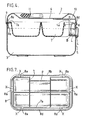
- FIGURE 1 shows a plan view of the cashbox in a closed position;
- FIGURE 2 shows a front elevational view of the box;
- FIGURE 3 shows a plan view of the box in an open position;
- FIGURE 4 shows a sectional view of the box taken on line IV-IV of FIGURE 1,
- FIGURE 5 shows a fragmentary view looking in the direction of arrow A in FIGURE 3;
- FIGURE 6 shows a fragmentary sectional view taken on line VI-VI of FIGURE 3, and
- FIGURE 7 shows a plan view of a coin tray and peripheral seal of the box just after removal from a mould (not shown).
- FIGURES 1 to 6 show a cashbox 1 of the general type shown in our patent application No. 2155443A. The main features of difference between the cashbox shown in that patent application and the cashbox 1 reside in the fact that the cashbox 1 has a
lid 2 of smaller depth thanbase 3; a key-operatedcylinder lock 4 is provided on afront wall portion 5 of the box 3 (rather than on atop panel portion 6 of the lid 2) and in that a different form ofcoin tray 7 and peripheral seal or seating orlocation bead 8 are provided. Therefore, the present description will be generally directed to discussion of these features. - FIGURE 3 shows the cashbox 1 in an open position with the
peripheral seal 8 seated on a plain free edge defining alip 3a of thebase 3. Thecoin tray 7 is supported by theseal 8 and has aperipheral flange 7a which rests loosely on, but is removable from, six inwardly directed,tabs 8a of theseal 8. Part of thecoin tray 7 has been shown cut-away in FIGURE 3 for ease of illustration. The reason for the slightly irregular configuration ofco-operating flange 7a andtabs 8a as shown in FIGURE 3 should be apparent from FIGURE 7 which shows that, in this instance, thetray 7 andseal 8 are produced originally together as a one-piece plastics moulding (again for ease of manufacture). Themoulding tabs 8a which will support theflange 7a, on rotation through 180° of thetray 7 relative to theseal 8 in the plane of the paper as shown in FIGURES 3 and 7. The overall configuration of thecoin tray 7 should be apparent from the FIGURES, and in this instance, it will be noted that wall portions of thetray 7 do not extend up into thelid 2 when the cashbox 1 is closed. - The
seal 8 itself is a very tight fit on thelip 3a ofbase 3 since it is designed essentially to remain attached to the base at all times, although it is still removable if required. Theseal 8 has a rectangular cut-outportion 8b (see FIGURE 7) which very closely embraceshinge 9. Theupper surface 8c ofseal 8 is flattened at the back thereof to accommodate the back edge of the lid (see FIGURE 3 and FIGURE 6) but is provided with a slightly raisedrim 8d (see FIGURE 3 and FIGURE 4) which extends around the front and sides of the seal and which marginally overlaps front and side wall portions of thelid 2 when the box 1 is closed. Theseal 8 has amain wall 8e which extends downwardly and engages tightly against the inside of the base (see FIGURE 6). Additionally, to aid in tight engagement and correct location of theseal 8 onbox 3, two taped lugs L forming downwardly depending extensions of themain wall 8e closely embrace the barrel B of the cylinder lock 4 (see FIGURE 5). FIGURE 2 shows how theseal 8 appears interposed between thelid 2 andbase 3 when the box 1 is closed. - From the foregoing description and drawings the form of the
coin tray 7 andseal 8 should be readily apparent as will be the seating of the seal on the base, the loose support of the tray on the seal and easy removal of the tray from the seal, when required, merely by lifting the tray off the seal, in order to gain access to the interior of the base. Additionally, the cash box by way of itsperipheral seal 8 is lockable in a tamper-proof manner and functional with the coin tray removed. - The
lid 2 is releasably lockable to thebase 3 bylocking mechanism cylinder lock 4 andlocking bar 10 welded in position on the underside of the lid (see FIGURE 3).Lock 4 has anotched tongue 4a which is rotatable with the barrel B of the lock from a non-locking position (FIGURE 5) to alocking position 4′a (shown in chain dotted lines in FIGURE 5 - also see FIGURE 4) in which thebar 10 is received in notch N of thetongue 4a. The centre front portion p oftray 7 is recessed so as to provide clear freedom of movement for thetongue 4a. A handle H is provided in a recessed part of thetop wall portion 6 of thelid 2. - The present invention could be utilised with a lid and base of similar depth and the coin tray itself may be configured to extend into the lid when the box is closed. The tray and seal need not necessarily be originally made integrally but such a production method has obvious cost advantages. In other embodiments the lock could be provided on the lid.
- It is to be understood that the scope of the present invention is not to be unduly limited by the particular choice of terminology and that a specific term may be replaced by any equivalent or generic term where sensible. Further it is to be understood that individual features, method or functions related to the cash box, coin tray or seal and/or combinations thereof might be patentably inventive.
- Therefore, for example, there is further provided in accordance with the present invention a method of making a coin tray and peripheral seal for a cashbox having a lid and a base, said method comprising:-
- a) moulding the coin tray and peripheral seal in one piece;
- b) separating the coin tray from the seal and reorientating the tray relative to the seal in use on the cashbox such that the tray rests on the seal with said seal being seated on the base, said tray being readily removable from the box, in order to give access to the interior of the base, with the seal remaining seated on the base.
- Further according to the present invention there is provided a cashbox having a peripheral seal which is non-integrally formed with the box and which is interposed or interposable between a lid and base of the box, said box having a coin tray (or at least a part thereof) which is removable from the box, said box being closable and lockable while said coin tray (or at least said part thereof) is removed.
Claims (9)
Applications Claiming Priority (2)
| Application Number | Priority Date | Filing Date | Title |
|---|---|---|---|
| GB8813580 | 1988-06-08 | ||
| GB8813580A GB2219572B (en) | 1988-06-08 | 1988-06-08 | Cashbox |
Publications (3)
| Publication Number | Publication Date |
|---|---|
| EP0345976A2 true EP0345976A2 (en) | 1989-12-13 |
| EP0345976A3 EP0345976A3 (en) | 1991-01-30 |
| EP0345976B1 EP0345976B1 (en) | 1994-09-21 |
Family
ID=10638297
Family Applications (1)
| Application Number | Title | Priority Date | Filing Date |
|---|---|---|---|
| EP89305348A Expired - Lifetime EP0345976B1 (en) | 1988-06-08 | 1989-05-26 | Cashbox |
Country Status (5)
| Country | Link |
|---|---|
| US (1) | US5168987A (en) |
| EP (1) | EP0345976B1 (en) |
| DE (1) | DE68918336T2 (en) |
| ES (1) | ES2059748T3 (en) |
| GB (1) | GB2219572B (en) |
Cited By (2)
| Publication number | Priority date | Publication date | Assignee | Title |
|---|---|---|---|---|
| WO1995020338A1 (en) * | 1994-01-26 | 1995-08-03 | Helix Limited | Cash box |
| USD886899S1 (en) | 2016-04-20 | 2020-06-09 | Steven Leong Jung | Coin holder for cash register |
Families Citing this family (9)
| Publication number | Priority date | Publication date | Assignee | Title |
|---|---|---|---|---|
| CZ3324U1 (en) | 1994-03-11 | 1995-05-17 | Koval, S.R.O. | Portable case box |
| DE29913188U1 (en) * | 1999-07-28 | 1999-11-18 | Drilbox Georg Knoblauch GmbH, 89537 Giengen | Toolbox |
| US6490774B2 (en) * | 2000-02-22 | 2002-12-10 | Odie Kenneth Carter | Added coin compartments for current cash tills |
| US20100180804A1 (en) * | 2008-08-11 | 2010-07-22 | Master Lock Company Llc | Locking enclosure |
| JP5527347B2 (en) * | 2012-03-26 | 2014-06-18 | 沖電気工業株式会社 | Paper sheet storage and paper sheet handling device |
| USD978477S1 (en) * | 2019-06-06 | 2023-02-14 | Rksa, Llc | Cash box with covered coin tray |
| USD1040468S1 (en) * | 2024-01-09 | 2024-08-27 | Chuanlong Gu | Cash box |
| USD1040469S1 (en) * | 2024-01-09 | 2024-08-27 | Chuanlong Gu | Cash box |
| USD1043026S1 (en) * | 2024-01-19 | 2024-09-17 | Yiwu Shine E Garment Co., Ltd. | Cash box |
Citations (4)
| Publication number | Priority date | Publication date | Assignee | Title |
|---|---|---|---|---|
| US2213821A (en) * | 1937-11-24 | 1940-09-03 | Herschel E Mccurdy | Traveling bag |
| FR2490191A1 (en) * | 1980-09-15 | 1982-03-19 | Poulain Chocolat | Plastics lid for rectangular cardboard container - has hinged edge with U=section frame which houses on top edge of box and has tear=off seal |
| FR2510366A1 (en) * | 1981-07-30 | 1983-02-04 | Becton Dickinson Co | INSTRUMENT SUPPORT FOR TRANSPORT BRIEF, AND INSTRUMENT TRANSPORT BRIEFCASE |
| GB2155443A (en) * | 1984-03-12 | 1985-09-25 | Helix Ltd | Portable cash box |
Family Cites Families (16)
| Publication number | Priority date | Publication date | Assignee | Title |
|---|---|---|---|---|
| US374149A (en) * | 1887-11-29 | Cash-box | ||
| US455624A (en) * | 1891-07-07 | Combined ticket-case and cash-box | ||
| US886345A (en) * | 1907-05-11 | 1908-05-05 | Robert S Burns | Cash-box. |
| US1146230A (en) * | 1914-06-17 | 1915-07-13 | Oscar Anderson | Locking means for boxes. |
| US1463360A (en) * | 1922-04-19 | 1923-07-31 | Foote Leonard | Sealing ring |
| GB274783A (en) * | 1927-05-17 | 1927-07-28 | Avon James Gray | Improvements in boxes and containers for tobacco, biscuits or other articles or material |
| US2522768A (en) * | 1947-01-30 | 1950-09-19 | Merriam Mfg Company | Cashbox |
| US2508283A (en) * | 1948-03-17 | 1950-05-16 | Albert U Nelson | Portable combination cash and ticket box |
| US2804197A (en) * | 1954-02-12 | 1957-08-27 | William R Popkess | Cash box |
| US3410018A (en) * | 1966-12-06 | 1968-11-12 | Old Pal Inc | Tackle box and rod pack |
| US3613872A (en) * | 1969-04-10 | 1971-10-19 | James G Donnelly | Receptacle device for food and beverage products or the like |
| US3915304A (en) * | 1974-08-08 | 1975-10-28 | Daniel Pasco | Heat insulated food retainer |
| DE3032915C2 (en) * | 1980-09-02 | 1984-08-30 | Drägerwerk AG, 2400 Lübeck | Closure of carrying containers for breathing apparatus |
| US4611711A (en) * | 1985-03-12 | 1986-09-16 | Helix Limited | Cash box |
| GB2172267B (en) * | 1985-03-13 | 1988-12-29 | Alan Frank Grounds | A container for money, tokens or saving stamps |
| US4714158A (en) * | 1985-08-12 | 1987-12-22 | Waterloo Industries, Inc. | Molded tool tray assembly |
-
1988
- 1988-06-08 GB GB8813580A patent/GB2219572B/en not_active Expired - Fee Related
-
1989
- 1989-05-26 DE DE68918336T patent/DE68918336T2/en not_active Expired - Fee Related
- 1989-05-26 EP EP89305348A patent/EP0345976B1/en not_active Expired - Lifetime
- 1989-05-26 ES ES89305348T patent/ES2059748T3/en not_active Expired - Lifetime
-
1992
- 1992-03-09 US US07/847,863 patent/US5168987A/en not_active Expired - Fee Related
Patent Citations (4)
| Publication number | Priority date | Publication date | Assignee | Title |
|---|---|---|---|---|
| US2213821A (en) * | 1937-11-24 | 1940-09-03 | Herschel E Mccurdy | Traveling bag |
| FR2490191A1 (en) * | 1980-09-15 | 1982-03-19 | Poulain Chocolat | Plastics lid for rectangular cardboard container - has hinged edge with U=section frame which houses on top edge of box and has tear=off seal |
| FR2510366A1 (en) * | 1981-07-30 | 1983-02-04 | Becton Dickinson Co | INSTRUMENT SUPPORT FOR TRANSPORT BRIEF, AND INSTRUMENT TRANSPORT BRIEFCASE |
| GB2155443A (en) * | 1984-03-12 | 1985-09-25 | Helix Ltd | Portable cash box |
Cited By (3)
| Publication number | Priority date | Publication date | Assignee | Title |
|---|---|---|---|---|
| WO1995020338A1 (en) * | 1994-01-26 | 1995-08-03 | Helix Limited | Cash box |
| US6006558A (en) * | 1994-01-26 | 1999-12-28 | Helix Limited | Cash box |
| USD886899S1 (en) | 2016-04-20 | 2020-06-09 | Steven Leong Jung | Coin holder for cash register |
Also Published As
| Publication number | Publication date |
|---|---|
| US5168987A (en) | 1992-12-08 |
| EP0345976B1 (en) | 1994-09-21 |
| GB2219572B (en) | 1992-08-19 |
| DE68918336D1 (en) | 1994-10-27 |
| GB8813580D0 (en) | 1988-07-13 |
| ES2059748T3 (en) | 1994-11-16 |
| EP0345976A3 (en) | 1991-01-30 |
| GB2219572A (en) | 1989-12-13 |
| DE68918336T2 (en) | 1995-05-04 |
Similar Documents
| Publication | Publication Date | Title |
|---|---|---|
| CA1286267C (en) | Wastebasket and inner liner retainer | |
| US6412637B1 (en) | Food storage containers | |
| US5356017A (en) | Child resistant closure with recessed latch | |
| EP0345976B1 (en) | Cashbox | |
| US20040079757A1 (en) | Container with hinged lid | |
| JPH05193702A (en) | Locking device for garbage container | |
| US4969572A (en) | End closure having a push open lid portion | |
| US20050205579A1 (en) | Bag retention apparatus and method | |
| US4505404A (en) | Container with integral closure | |
| US4789078A (en) | Wastebasket with lid catch | |
| US5411160A (en) | Child resistant closure | |
| USRE34263E (en) | End closure having a push open lid portion | |
| US3338464A (en) | Record containers | |
| WO2020206547A1 (en) | Lockable and stackable container with secure lid | |
| US4555035A (en) | Container closure with tunnel member | |
| US20020179644A1 (en) | Toggle action dispensing closure with locking means | |
| JP2007045422A (en) | Hinge cap with falsification-proof function | |
| EP0739294B1 (en) | Closure with a tamper-evident element | |
| JP2517851Y2 (en) | Food packaging containers | |
| JP3708327B2 (en) | Airtight container | |
| JP3242507B2 (en) | Garbage container | |
| JP2602484B2 (en) | Flat shell flat storage box | |
| JP2001301789A (en) | Lid for container | |
| CA1264155A (en) | Container closure with tunnel member | |
| JP3002810U (en) | Content |
Legal Events
| Date | Code | Title | Description |
|---|---|---|---|
| PUAI | Public reference made under article 153(3) epc to a published international application that has entered the european phase |
Free format text: ORIGINAL CODE: 0009012 |
|
| AK | Designated contracting states |
Kind code of ref document: A2 Designated state(s): DE ES FR GB IT NL |
|
| PUAL | Search report despatched |
Free format text: ORIGINAL CODE: 0009013 |
|
| AK | Designated contracting states |
Kind code of ref document: A3 Designated state(s): DE ES FR GB IT NL |
|
| 17P | Request for examination filed |
Effective date: 19910727 |
|
| 17Q | First examination report despatched |
Effective date: 19930315 |
|
| RBV | Designated contracting states (corrected) |
Designated state(s): DE ES FR IT NL |
|
| GRAA | (expected) grant |
Free format text: ORIGINAL CODE: 0009210 |
|
| AK | Designated contracting states |
Kind code of ref document: B1 Designated state(s): DE ES FR IT NL |
|
| PG25 | Lapsed in a contracting state [announced via postgrant information from national office to epo] |
Ref country code: IT Free format text: LAPSE BECAUSE OF FAILURE TO SUBMIT A TRANSLATION OF THE DESCRIPTION OR TO PAY THE FEE WITHIN THE PRE;WARNING: LAPSES OF ITALIAN PATENTS WITH EFFECTIVE DATE BEFORE 2007 MAY HAVE OCCURRED AT ANY TIME BEFORE 2007. THE CORRECT EFFECTIVE DATE MAY BE DIFFERENT FROM THE ONE RECORDED.SCRIBED TIME-LIMIT Effective date: 19940921 |
|
| ET | Fr: translation filed | ||
| REF | Corresponds to: |
Ref document number: 68918336 Country of ref document: DE Date of ref document: 19941027 |
|
| REG | Reference to a national code |
Ref country code: ES Ref legal event code: FG2A Ref document number: 2059748 Country of ref document: ES Kind code of ref document: T3 |
|
| PLBE | No opposition filed within time limit |
Free format text: ORIGINAL CODE: 0009261 |
|
| STAA | Information on the status of an ep patent application or granted ep patent |
Free format text: STATUS: NO OPPOSITION FILED WITHIN TIME LIMIT |
|
| 26N | No opposition filed | ||
| PGFP | Annual fee paid to national office [announced via postgrant information from national office to epo] |
Ref country code: ES Payment date: 19960521 Year of fee payment: 8 |
|
| PGFP | Annual fee paid to national office [announced via postgrant information from national office to epo] |
Ref country code: FR Payment date: 19960529 Year of fee payment: 8 |
|
| PGFP | Annual fee paid to national office [announced via postgrant information from national office to epo] |
Ref country code: NL Payment date: 19960531 Year of fee payment: 8 |
|
| PGFP | Annual fee paid to national office [announced via postgrant information from national office to epo] |
Ref country code: DE Payment date: 19960731 Year of fee payment: 8 |
|
| PG25 | Lapsed in a contracting state [announced via postgrant information from national office to epo] |
Ref country code: ES Free format text: LAPSE BECAUSE OF NON-PAYMENT OF DUE FEES Effective date: 19970527 |
|
| PG25 | Lapsed in a contracting state [announced via postgrant information from national office to epo] |
Ref country code: NL Effective date: 19971201 |
|
| PG25 | Lapsed in a contracting state [announced via postgrant information from national office to epo] |
Ref country code: FR Free format text: LAPSE BECAUSE OF NON-PAYMENT OF DUE FEES Effective date: 19980130 |
|
| NLV4 | Nl: lapsed or anulled due to non-payment of the annual fee |
Effective date: 19971201 |
|
| PG25 | Lapsed in a contracting state [announced via postgrant information from national office to epo] |
Ref country code: DE Free format text: LAPSE BECAUSE OF NON-PAYMENT OF DUE FEES Effective date: 19980203 |
|
| REG | Reference to a national code |
Ref country code: FR Ref legal event code: ST |
|
| REG | Reference to a national code |
Ref country code: ES Ref legal event code: FD2A Effective date: 19990301 |