EP0345501A1 - A press with extended nip - Google Patents
A press with extended nip Download PDFInfo
- Publication number
- EP0345501A1 EP0345501A1 EP89108952A EP89108952A EP0345501A1 EP 0345501 A1 EP0345501 A1 EP 0345501A1 EP 89108952 A EP89108952 A EP 89108952A EP 89108952 A EP89108952 A EP 89108952A EP 0345501 A1 EP0345501 A1 EP 0345501A1
- Authority
- EP
- European Patent Office
- Prior art keywords
- press
- press shoe
- support
- pressure
- shoe
- Prior art date
- Legal status (The legal status is an assumption and is not a legal conclusion. Google has not performed a legal analysis and makes no representation as to the accuracy of the status listed.)
- Granted
Links
Images

Classifications
-
- D—TEXTILES; PAPER
- D21—PAPER-MAKING; PRODUCTION OF CELLULOSE
- D21F—PAPER-MAKING MACHINES; METHODS OF PRODUCING PAPER THEREON
- D21F3/00—Press section of machines for making continuous webs of paper
- D21F3/02—Wet presses
- D21F3/0209—Wet presses with extended press nip
- D21F3/0218—Shoe presses
Definitions
- the present invention relates to a press with extended nip for paper or board machines, comprising a support means acting as counter member; a pressure means disposed opposite the support means and comprising a press shoe and a carrying element carrying the press shoe and designed to be secured to a stand, said press shoe, together with the support means, forming a pressing zone with extended nip; at least one endless movable belt, impervious to liquid, being arranged to pass through said pressing zone in sliding contact with the press shoe; and at least one endless, liquid-absorbing felt, arranged to pass through said pressing zone together with a fiber web to be dewatered, said pressure means comprising a plurality of jacks disposed in at least one row across the belt and having piston rods acting on the press shoe to force it against the support means.
- Extended nip presses of substantially the above type are described in a large number of patent specifications, see, for instance US 4 272 317, US Re. 30268, US 4 568 423 and FI 71369. It is also known to design the press shoe itself as a part of a jacklike means, as described in e.g. US 3 853 698, US 4 556 454 and EP 0 254 819.
- the pressure means of the known presses are often relatively complicated to manufacture, assemble and dismantle for maintenance or replacement, as well as having functional deficiencies during operation.
- the object of the present invention is to provide a press with an improved pressure means, which functions in a satisfactory manner, is easy to manufacture with a resultant reduction in manufacturing costs, and is simple to install and dismantle for maintenance or replacement.
- the press according to the present invention is substantially characterized in that the press shoe is freely supported by the piston rods without rigid mechanical connection therebetween, and that the pressure means is provided with a support bearing disposed downstream of the press shoe to absorb horizontal forces acting on the press shoe during operation, said support bearing comprising a stationary support element mounted on the carrying element.
- the wet press comprises a support means 2 acting as counter member which, in the embodiment shown, consists of a rotating counter roll, and a belt 3 impervious to liquid, running in a loop over a plurality of rolls (not shown) and over a predetermined sector of the counter roll 2.
- a pressure means 4 is disposed opposite the counter roll 2, said pressure means comprising a press shoe 5 which, together with the counter roll 2, forms a pressing zone with extended nip within said predetermined sector of the counter roll 2 where the belt 3 runs over the counter roll 2.
- Two endless felts 6, 7 are arranged to run in individual loops over a plurality of rolls (not shown) and through the pressing zone. During operation, the continuous wet fiber web 1 passes through the pressing zone together with the belt 3 and felts 6, 7, which receive liquid pressed out of the fiber web 1 located between the felts 6, 7.
- the pressure means 4 located within the loop of the belt 3, comprises a carrying element 41 which forms a frame and being provided with suitable attachment means 8 for securing the pressure means 4 to a stand 9 of the wet press.
- the press shoe 5 suitably consists of an upper sliding part 10 and a lower frame part 11, the sliding part 10 being provided with a sliding surface 12 along which the belt 3 travels in sliding contact.
- the press shoe 5 disposed opposite the counter roll 2 extends transversely across the belt 3, parallel to the axis of rotation of the counter roll 2.
- the press shoe 5 is provided with a channel system 13 for the supply of lubricating fluid to the sliding surface 12 so that a friction-reducing film is formed and maintained between the belt 3 and press shoe 5, while at the same time a hydrodynamic pressure is obtained.
- a channel system (not shown) for collecting and recirculating most of the lubricating fluid passing over the sliding surface l2 of the press shoe 5, the downstream edge of the press shoe 5 suitably being rounded so that the lubricating fluid can run off more easily.
- the pressure means 4 comprises a plurality of jacks 14 disposed in said carrying element 41.
- the carrying element 41 consists of an oblong, rectangular jack unit 15 extending transversely across the belt 3 parallel to the press shoe 5.
- the jacks 14 are disposed in two rows with a plurality of jacks and the same number of jacks in each row.
- the jack unit 15 includes a block 16 which is provided with cylindrical cavities 17 for the pistons 18 of the jacks 14 and a plate-like top element 19 closing the cavities 17 at the top and provided with apertures 20 for the piston rods 21 of the jacks.
- the block 16 is provided with a bottom element 22 closing the cavities 17 at the bottom.
- said bottom element and block may be made in one piece, the cavities 17 in this case do not pass right through.
- the cavities 11 are connected via channel systems 23, 24 to a pressure-medium source.
- the channel systems may suitably be so divided that two or more groups of jacks with one or more jacks in each group can be placed under different pressures so that the fiber web is compressed to varying extents in transverse direction.
- the ends of the piston rods 21 freely abut the press shoe 5, i.e. there is no rigid mechanical connection therebetween.
- the pressure means is provided with a plurality of hydrostatic pressure pockets 25 disposed in a row, each of which including an upper, relatively shallow, rectangular pressure chamber 26 immersed in the sliding surface 12 of the press shoe 5, and a vertical connecting chamber 27 in direct communication with the pressure chamber 26 and having sufficiently large cross section area for the same pressure to prevail throughout the pressure pocket 25.
- the connecting chamber 27 extends from the pressure chamber 26 through the entire press shoe 5 and continues a suitable distance down into the carrying element 41, or more specifically the top plate 19, so that the bottom 28 of the pressure pocket 25 is located in the top plate 19.
- each pressure pocket 25 between the top plate 19 (carrying element 41) and press shoe 5 is formed by a sleeve 29 extending through opposite apertures 33, 42, down towards the bottom 28 of the pressure pocket 25 and a distance into the press shoe 5.
- the sleeves 29 are rigidly attached to the top plate 19 and are provided at the top with resilient seals 30 sealing against the aperture wall in the press shoe 5.
- a lower seal may alternatively be disposed to seal against the aperture wall in the top plate 19.
- the vertical connecting chambers 21 are aligned to each other so that the sleeves 29 will be in a straight line, thus ensuring that none of the sleeves 29 becomes deformed if the press shoe 5 is slightly inclined.
- a horizontal channel 31 extends which supplies the pressure pockets 25 with pressure fluid from a source, through individual narrow throttle holes 32 with capillary action.
- the throttle holes 32 have sufficiently small through flow area to ensure that a temporary pressure change in a certain pressure pocket 25 will not affect the pressure in the other pressure pockets 25 due to pressure fluid being quickly pressed into or out of the pressure pocket 25 concerned until equilibrium is achieved again in the system. In this way a stabilized pressure distribution is achieved in the pockets 25 and across the belt 3.
- each sleeve 29 is slightly less than that of the aperture 33 in the press shoe 5 so that a small clearance is formed therebetween, said clearance thus being sealed by the seal 30 which is in sliding contact with the wall of the aperture. Since the piston rods are not secured to the press shoe 5, and the sleeves 29 are shaped and disposed as described, the press shoe 5 is allowed to move to a limited extent in all directions. The press shoe 5 can thus be considered as being free-flowing within said limitations. It will be understood that a limited inclination of the press shoe 5 also is possible within the limits of the resilience of the seals 30 and the clearance between each sleeve 29 and the opposite aperture walls in the press shoe 5 irrespective of the position of the press shoe 5 in relation to the top plate 19.
- the pressure means 4 comprises a support bearing 34 disposed downstream of the press shoe 5.
- said support bearing 34 comprises a stationary support element 35 secured to the top plate 19, and rolling bodies 36 rotatably journal led on the downstream side of the press shoe 5 and being in contact with a support surface of the stationary support element 35 and an opposing support surface of the press shoe 5.
- the rolling bodies comprise a plurality of rollers distributed along the side of the press shoe 5.
- the rolling bodies may alternatively consist of spheres.
- FIGS 3 and 4 it is shown an alternative embodiment of a support bearing according to the invention, comprising a support element 37 rigidly attached to the top plate 19 and provided or formed with a plurality of projections 38 facing the press shoe 5.
- the projections have a convex support surface 39 which is in contact with an opposing support and sliding surface 40 on the downstream side of the press shoe 5.
- a second press shoe may be used, having a second endless pressure belt rotating around it.
- the sliding surface 12 of the press shoe 5 shown and the sliding surface of the press shoe of the second support means are in this case adjusted to fit each other. Both the sliding surfaces are generally made flat, but one of them might even be convex and the other correspondingly concave.
- jack units only at the ends of the press shoes, i.e. at the edges of the pressure belt, and between these end units to use, for instance, jacks with an upstream jack, which is elongate and disposed transverse to the direction of the machine, and a corresponding downstream jack.
Abstract
Description
- The present invention relates to a press with extended nip for paper or board machines, comprising a support means acting as counter member; a pressure means disposed opposite the support means and comprising a press shoe and a carrying element carrying the press shoe and designed to be secured to a stand, said press shoe, together with the support means, forming a pressing zone with extended nip; at least one endless movable belt, impervious to liquid, being arranged to pass through said pressing zone in sliding contact with the press shoe; and at least one endless, liquid-absorbing felt, arranged to pass through said pressing zone together with a fiber web to be dewatered, said pressure means comprising a plurality of jacks disposed in at least one row across the belt and having piston rods acting on the press shoe to force it against the support means.
- Extended nip presses of substantially the above type are described in a large number of patent specifications, see, for instance US 4 272 317, US Re. 30268, US 4 568 423 and FI 71369. It is also known to design the press shoe itself as a part of a jacklike means, as described in e.g. US 3 853 698, US 4 556 454 and EP 0 254 819.
- The pressure means of the known presses are often relatively complicated to manufacture, assemble and dismantle for maintenance or replacement, as well as having functional deficiencies during operation.
- The object of the present invention is to provide a press with an improved pressure means, which functions in a satisfactory manner, is easy to manufacture with a resultant reduction in manufacturing costs, and is simple to install and dismantle for maintenance or replacement.
- The press according to the present invention is substantially characterized in that the press shoe is freely supported by the piston rods without rigid mechanical connection therebetween, and that the pressure means is provided with a support bearing disposed downstream of the press shoe to absorb horizontal forces acting on the press shoe during operation, said support bearing comprising a stationary support element mounted on the carrying element.
- The invention will be described further in the following with reference to the drawings.
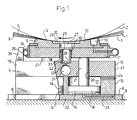
- Figure 1 shows parts of a wet press with extended nip, equipped with a pressing means in accordance with the present invention.
- Figure 2 shows parts of the pressure means according to Figure 1 from above.
- Figure 3 shows a support bearing according to an alternative embodiment to that in the pressure means according to Figures 1 and 2.
- Figure 4 shows parts of the support bearing according to Figure 3 from above.
- With reference to Figure 1 it is schematically shown therein parts of a wet press disposed in the wet section of a paper machine or board machine for pressing water out of a formed wet fiber web 1 and compressing said web. The wet press comprises a support means 2 acting as counter member which, in the embodiment shown, consists of a rotating counter roll, and a
belt 3 impervious to liquid, running in a loop over a plurality of rolls (not shown) and over a predetermined sector of the counter roll 2. A pressure means 4 is disposed opposite the counter roll 2, said pressure means comprising apress shoe 5 which, together with the counter roll 2, forms a pressing zone with extended nip within said predetermined sector of the counter roll 2 where thebelt 3 runs over the counter roll 2. Two endless felts 6, 7 are arranged to run in individual loops over a plurality of rolls (not shown) and through the pressing zone. During operation, the continuous wet fiber web 1 passes through the pressing zone together with thebelt 3 and felts 6, 7, which receive liquid pressed out of the fiber web 1 located between the felts 6, 7. - The pressure means 4, located within the loop of the
belt 3, comprises a carrying element 41 which forms a frame and being provided with suitable attachment means 8 for securing the pressure means 4 to a stand 9 of the wet press. - The
press shoe 5 suitably consists of an upper slidingpart 10 and alower frame part 11, thesliding part 10 being provided with asliding surface 12 along which thebelt 3 travels in sliding contact. Thepress shoe 5 disposed opposite the counter roll 2 extends transversely across thebelt 3, parallel to the axis of rotation of the counter roll 2. At the upstream portion, close to its edge, thepress shoe 5 is provided with achannel system 13 for the supply of lubricating fluid to the slidingsurface 12 so that a friction-reducing film is formed and maintained between thebelt 3 and pressshoe 5, while at the same time a hydrodynamic pressure is obtained. - At the downstream end of the
press shoe 5, and more specifically in itslower frame part 11, there is a channel system (not shown) for collecting and recirculating most of the lubricating fluid passing over the sliding surface l2 of thepress shoe 5, the downstream edge of thepress shoe 5 suitably being rounded so that the lubricating fluid can run off more easily. - The pressure means 4 comprises a plurality of
jacks 14 disposed in said carrying element 41. In the embodiment shown the carrying element 41 consists of an oblong,rectangular jack unit 15 extending transversely across thebelt 3 parallel to thepress shoe 5. In the preferred embodiment shown thejacks 14 are disposed in two rows with a plurality of jacks and the same number of jacks in each row. Thejack unit 15 includes ablock 16 which is provided with cylindrical cavities 17 for thepistons 18 of thejacks 14 and a plate-liketop element 19 closing the cavities 17 at the top and provided with apertures 20 for thepiston rods 21 of the jacks. Theblock 16 is provided with abottom element 22 closing the cavities 17 at the bottom. Alternatively, said bottom element and block may be made in one piece, the cavities 17 in this case do not pass right through. On both sides of thepistons 18 thecavities 11 are connected viachannel systems press shoe 5, i.e. there is no rigid mechanical connection therebetween. - Further, the pressure means is provided with a plurality of
hydrostatic pressure pockets 25 disposed in a row, each of which including an upper, relatively shallow,rectangular pressure chamber 26 immersed in the slidingsurface 12 of thepress shoe 5, and avertical connecting chamber 27 in direct communication with thepressure chamber 26 and having sufficiently large cross section area for the same pressure to prevail throughout thepressure pocket 25. The connectingchamber 27 extends from thepressure chamber 26 through theentire press shoe 5 and continues a suitable distance down into the carrying element 41, or more specifically thetop plate 19, so that thebottom 28 of thepressure pocket 25 is located in thetop plate 19. - The transition for each
pressure pocket 25 between the top plate 19 (carrying element 41) and pressshoe 5 is formed by asleeve 29 extending throughopposite apertures bottom 28 of thepressure pocket 25 and a distance into thepress shoe 5. In the embodiment shown thesleeves 29 are rigidly attached to thetop plate 19 and are provided at the top withresilient seals 30 sealing against the aperture wall in thepress shoe 5. A lower seal may alternatively be disposed to seal against the aperture wall in thetop plate 19. Thevertical connecting chambers 21 are aligned to each other so that thesleeves 29 will be in a straight line, thus ensuring that none of thesleeves 29 becomes deformed if thepress shoe 5 is slightly inclined. - In the
top plate 19, below thepressure pockets 25 and spaced a short predetermined distance from theirbottom surface 28, ahorizontal channel 31 extends which supplies thepressure pockets 25 with pressure fluid from a source, through individualnarrow throttle holes 32 with capillary action. Thethrottle holes 32 have sufficiently small through flow area to ensure that a temporary pressure change in acertain pressure pocket 25 will not affect the pressure in theother pressure pockets 25 due to pressure fluid being quickly pressed into or out of thepressure pocket 25 concerned until equilibrium is achieved again in the system. In this way a stabilized pressure distribution is achieved in thepockets 25 and across thebelt 3. - The diameter of each
sleeve 29 is slightly less than that of theaperture 33 in thepress shoe 5 so that a small clearance is formed therebetween, said clearance thus being sealed by theseal 30 which is in sliding contact with the wall of the aperture. Since the piston rods are not secured to thepress shoe 5, and thesleeves 29 are shaped and disposed as described, thepress shoe 5 is allowed to move to a limited extent in all directions. Thepress shoe 5 can thus be considered as being free-flowing within said limitations. It will be understood that a limited inclination of thepress shoe 5 also is possible within the limits of the resilience of theseals 30 and the clearance between eachsleeve 29 and the opposite aperture walls in thepress shoe 5 irrespective of the position of thepress shoe 5 in relation to thetop plate 19. There is therefore no definite fixed pivotal axis in the pressure means according to the present invention. A greater pressure on the downstream portion of thepress shoe 5 can be applied with the aid of the lefthand row ofjacks 14, seen in Figure 1, than on the upstream portion of thepress shoe 5 with the aid of the righthand row ofjacks 14, thus resulting in an inclination of thepress shoe 5. Such an inclination is desirable in order to achieve increasing pressure forces on the fiber web 1 in its direction of travel. - However, the
sleeves 29, along which thepress shoe 5 is slidable up och down, cannot absorb the considerable horizontal forces which are transmitted to thepress shoe 5 from thebelt 3 during operation. For this purpose the pressure means 4 according to the present invention comprises a support bearing 34 disposed downstream of thepress shoe 5. In the embodiment shown in Figures 1 and 2, said support bearing 34 comprises astationary support element 35 secured to thetop plate 19, androlling bodies 36 rotatably journal led on the downstream side of thepress shoe 5 and being in contact with a support surface of thestationary support element 35 and an opposing support surface of thepress shoe 5. In the embodiment shown in Figures 1 and 2 the rolling bodies comprise a plurality of rollers distributed along the side of thepress shoe 5. The rolling bodies may alternatively consist of spheres. - In Figures 3 and 4 it is shown an alternative embodiment of a support bearing according to the invention, comprising a
support element 37 rigidly attached to thetop plate 19 and provided or formed with a plurality ofprojections 38 facing thepress shoe 5. The projections have aconvex support surface 39 which is in contact with an opposing support and slidingsurface 40 on the downstream side of thepress shoe 5. - Instead of a rotating counter roll a second press shoe may be used, having a second endless pressure belt rotating around it. The sliding
surface 12 of thepress shoe 5 shown and the sliding surface of the press shoe of the second support means are in this case adjusted to fit each other. Both the sliding surfaces are generally made flat, but one of them might even be convex and the other correspondingly concave. - If desired it is of course also possible in a wet press according to the invention to use the jack units only at the ends of the press shoes, i.e. at the edges of the pressure belt, and between these end units to use, for instance, jacks with an upstream jack, which is elongate and disposed transverse to the direction of the machine, and a corresponding downstream jack.
Claims (8)
Priority Applications (1)
| Application Number | Priority Date | Filing Date | Title |
|---|---|---|---|
| AT89108952T ATE82604T1 (en) | 1988-05-25 | 1989-05-18 | WET PRESS WITH EXTENDED PRESSING ZONE. |
Applications Claiming Priority (2)
| Application Number | Priority Date | Filing Date | Title |
|---|---|---|---|
| SE8801934 | 1988-05-25 | ||
| SE8801934A SE461171C (en) | 1988-05-25 | 1988-05-25 | LONG NYP PRESSES BEFORE PAPER OR CARTON MACHINERY |
Publications (3)
| Publication Number | Publication Date |
|---|---|
| EP0345501A1 true EP0345501A1 (en) | 1989-12-13 |
| EP0345501B1 EP0345501B1 (en) | 1992-11-19 |
| EP0345501B2 EP0345501B2 (en) | 1996-12-27 |
Family
ID=20372414
Family Applications (1)
| Application Number | Title | Priority Date | Filing Date |
|---|---|---|---|
| EP89108952A Expired - Lifetime EP0345501B2 (en) | 1988-05-25 | 1989-05-18 | A press with extended nip |
Country Status (9)
| Country | Link |
|---|---|
| US (1) | US4917768A (en) |
| EP (1) | EP0345501B2 (en) |
| JP (1) | JP2693573B2 (en) |
| CN (1) | CN1014250B (en) |
| AT (1) | ATE82604T1 (en) |
| CA (1) | CA1322122C (en) |
| DE (1) | DE68903534T3 (en) |
| FI (1) | FI89286C (en) |
| SE (1) | SE461171C (en) |
Cited By (14)
| Publication number | Priority date | Publication date | Assignee | Title |
|---|---|---|---|---|
| DE4407405A1 (en) * | 1994-03-05 | 1995-09-07 | Escher Wyss Gmbh | Dryer section |
| DE4425915A1 (en) * | 1994-07-21 | 1996-02-01 | Voith Sulzer Papiermasch Gmbh | Long nip press for e.g. dewatering fibrous web materials |
| EP0812953A1 (en) * | 1996-05-31 | 1997-12-17 | Voith Sulzer Papiermaschinen GmbH | Shoe press |
| EP0812954A1 (en) * | 1996-05-31 | 1997-12-17 | Voith Sulzer Papiermaschinen GmbH | Press roll |
| WO1999016971A1 (en) * | 1997-09-30 | 1999-04-08 | Valmet-Karlstad Ab | Shoe press |
| WO1999016968A1 (en) * | 1997-09-30 | 1999-04-08 | Valmet-Karlstad Ab | Shoe press for paper or board machines |
| WO1999016969A1 (en) * | 1997-09-30 | 1999-04-08 | Valmet-Karlstad Ab | Shoe press and loading cylinder unit therefor |
| WO2001068975A1 (en) * | 2000-03-17 | 2001-09-20 | Metso Paper Karlstad Ab | Shoe press and shoe support device therefor |
| WO2003083210A1 (en) * | 2002-04-03 | 2003-10-09 | Metso Paper, Inc. | Long-nip press of a paper/board machine |
| DE10196358B4 (en) * | 2000-06-19 | 2011-03-10 | Metso Paper, Inc. | Extended nip press for a paper machine or board machine |
| DE102009045378A1 (en) | 2009-10-06 | 2011-04-07 | Voith Patent Gmbh | Press roller for use in press device in e.g. calender for formation of press gap for dehydration of paper in machine for manufacturing and/or smoothing paper, has supporting surface comprising multiple recesses without oil supply point |
| DE102009045414A1 (en) | 2009-10-07 | 2011-04-14 | Voith Patent Gmbh | press roll |
| EP3913133A1 (en) * | 2020-05-20 | 2021-11-24 | Valmet Technologies Oy | Sleeve roll for a wire section of a fiber web machine |
| EP3913134A1 (en) * | 2020-05-20 | 2021-11-24 | Valmet Technologies Oy | Sleeve roll |
Families Citing this family (45)
| Publication number | Priority date | Publication date | Assignee | Title |
|---|---|---|---|---|
| GB8615785D0 (en) * | 1986-06-27 | 1986-08-06 | Beecham Group Plc | Compounds |
| FI91789C (en) * | 1989-12-21 | 1994-08-10 | Tampella Oy Ab | Paper machine long zone press |
| SE464922B (en) * | 1990-05-08 | 1991-07-01 | Valmet Paper Machinery Inc | PRESS ROLL |
| US5389205A (en) * | 1990-11-23 | 1995-02-14 | Valmet Paper Machinery, Inc. | Method for dewatering of a paper web by pressing using an extended nip shoe pre-press zone on the forming wire |
| FI96789C (en) * | 1990-11-23 | 1996-08-26 | Valmet Paper Machinery Inc | Method and apparatus for dewatering a paper web by pressing |
| US5087325A (en) * | 1991-03-13 | 1992-02-11 | Beloit Corporation | Apparatus for manufacturing a dried web of paper |
| DE4113623C1 (en) * | 1991-04-26 | 1992-02-20 | J.M. Voith Gmbh, 7920 Heidenheim, De | |
| US5167768A (en) * | 1991-11-07 | 1992-12-01 | Beloit Corporation | Wide nip web press and method using a press shoe with two pivots |
| DE4138788C2 (en) * | 1991-11-26 | 1995-05-18 | Escher Wyss Gmbh | Device for dewatering a fibrous web |
| DE4409316C1 (en) * | 1994-03-18 | 1995-06-29 | Escher Wyss Gmbh | Long gap press assembly for fibre web |
| DE4410129A1 (en) * | 1994-03-24 | 1995-09-28 | Kleinewefers Gmbh | Press device for sheet material |
| FI942616A (en) * | 1994-06-03 | 1995-12-04 | Valmet Corp | Paper web pre-press |
| DE4435845C1 (en) * | 1994-10-07 | 1996-01-25 | Voith Sulzer Papiermasch Gmbh | Press roller esp. with flexible shell and internal press shoe |
| DE4442016C1 (en) * | 1994-11-25 | 1996-02-22 | Voith Sulzer Papiermasch Gmbh | Roll for handling or prodn. of strip material |
| DE19514142C1 (en) * | 1995-04-15 | 1996-07-11 | Voith Sulzer Papiermasch Gmbh | Simply serviceable pressure shoe for a yet strong paper press roller |
| DE19544978C2 (en) * | 1995-12-01 | 1998-07-30 | Voith Sulzer Papiermasch Gmbh | Press roll |
| DE19631638A1 (en) * | 1996-08-05 | 1998-02-12 | Voith Sulzer Papiermasch Gmbh | Press arrangement |
| US5897747A (en) * | 1997-08-08 | 1999-04-27 | Beloit Technologies, Inc. | Machine direction profiling of extended nip press shoe |
| US5997696A (en) * | 1997-09-30 | 1999-12-07 | Valmet-Karlstad Ab | Shoe press |
| US6042694A (en) * | 1997-09-30 | 2000-03-28 | Valmet-Karlstad Ab | Shoe press |
| US6159342A (en) * | 1997-09-30 | 2000-12-12 | Valmet-Karlstad Ab | Shoe press |
| US6139691A (en) * | 1997-09-30 | 2000-10-31 | Valmet-Karlstad Ab | Shoe press |
| SE510553C2 (en) * | 1997-09-30 | 1999-05-31 | Valmet Karlstad Ab | Shoe press for a paper or cardboard machine |
| US6017422A (en) * | 1997-09-30 | 2000-01-25 | Valmet-Karlstad Ab | Shoe press |
| US6083352A (en) * | 1998-01-30 | 2000-07-04 | Valmet Corporation | Shoe press |
| DE19828156A1 (en) * | 1998-06-24 | 1999-12-30 | Voith Sulzer Papiertech Patent | Device for smoothing a web of material |
| US6248210B1 (en) * | 1998-11-13 | 2001-06-19 | Fort James Corporation | Method for maximizing water removal in a press nip |
| SE9804346D0 (en) * | 1998-12-16 | 1998-12-16 | Valmet Corp | Method and apparatus for calendering paper |
| SE515573C2 (en) * | 1999-11-26 | 2001-09-03 | Valmet Karlstad Ab | Method and apparatus for oil evacuation from a shoe press unit |
| US6402890B1 (en) * | 1999-12-08 | 2002-06-11 | Metso Paper Karlstad Ab | Method and device for oil evacuation from a shoe press unit |
| US6387219B2 (en) * | 1999-12-10 | 2002-05-14 | Metso Paper, Inc. | Press device having an extended press nip for pressing a traveling paper or paperboard web |
| SE515484C2 (en) * | 1999-12-10 | 2001-08-13 | Metso Paper Inc | Pressing device with extended press nip for pressing a running paper or cardboard web |
| US7172679B2 (en) * | 1999-12-10 | 2007-02-06 | Metso Paper, Inc. | Press device having an extended press nip for pressing of a travelling paperboard web, and procedure for controlling the pressure curve in the machine direction by such press nip |
| EP1266081A1 (en) * | 2000-02-18 | 2002-12-18 | Metso Paper Karlstad Aktiebolag | Press device having an extended nip for pressing a running paper or paperboard web |
| FI20002630A0 (en) * | 2000-11-30 | 2000-11-30 | Teuvo Rajamaeki | Long press machine for machines that carry fiber webs |
| FI116228B (en) * | 2001-07-05 | 2005-10-14 | Vaahto Oy | A method for controlling a position of a loading shoe in a long nip press and a long nip press |
| DE10260202A1 (en) * | 2002-06-25 | 2004-01-22 | Voith Paper Patent Gmbh | Device for influencing and / or monitoring a pressure profile |
| DE10259232A1 (en) * | 2002-12-17 | 2004-07-15 | Eduard Küsters Maschinenfabrik GmbH & Co. KG | Device for forming an elongated gap |
| SE527236C2 (en) * | 2004-05-26 | 2006-01-24 | Metso Paper Karlstad Ab | Press, method at a press and press elements for a press |
| US20070015455A1 (en) * | 2005-07-13 | 2007-01-18 | York International Corporation | Orifice boundary layer suction method and system |
| JP4779564B2 (en) * | 2005-10-18 | 2011-09-28 | 王子製紙株式会社 | Shoe press apparatus for paper machine and paper manufacturing method |
| CN100424301C (en) * | 2005-12-22 | 2008-10-08 | 高维成 | Pulley type truss-string arc-scaffolding combined structural system |
| US9650743B2 (en) | 2012-08-15 | 2017-05-16 | Voith Patent Gmbh | Sealing device, suction roll and method for producing and/or processing a paper, cardboard or tissue web |
| SE542214C2 (en) | 2018-10-12 | 2020-03-10 | Valmet Oy | A tissue paper making machine and a method of operating a tissue paper making machine |
| CN112522984B (en) * | 2020-12-17 | 2022-06-07 | 淄博泰鼎机械科技有限公司 | Shoe type presser |
Citations (5)
| Publication number | Priority date | Publication date | Assignee | Title |
|---|---|---|---|---|
| FR2219836A1 (en) * | 1973-03-01 | 1974-09-27 | Escher Wyss Sa | |
| DE3030233A1 (en) * | 1980-08-09 | 1982-02-18 | J.M. Voith Gmbh, 7920 Heidenheim | Wet fibre web press - has compressible sliding shoe to allow for variations in material thickness |
| EP0066528A1 (en) * | 1981-05-26 | 1982-12-08 | Beloit Corporation | Extended nip shoe |
| DE3410172A1 (en) * | 1983-03-23 | 1984-09-27 | Valmet Oy, Helsinki | LONG SPLIT PRESS OF A PAPER MACHINE |
| DE3317457A1 (en) * | 1983-05-13 | 1984-11-15 | J.M. Voith Gmbh, 7920 Heidenheim | Pressing device for material in strip form, in particular for dewatering a web of paper |
Family Cites Families (8)
| Publication number | Priority date | Publication date | Assignee | Title |
|---|---|---|---|---|
| US30268A (en) * | 1860-10-02 | Pierre d | ||
| US3853698A (en) * | 1972-04-17 | 1974-12-10 | Beloit Corp | Large roll hydraulic press with pressurized fluid supports |
| US4272317A (en) * | 1979-11-01 | 1981-06-09 | Beloit Corporation | Roll bearing alignment |
| FI65103C (en) * | 1982-05-05 | 1984-03-12 | Tampella Oy Ab | LAONGZONSPRESS FOER EN PAPPERSMASKIN |
| FI70952C (en) * | 1982-10-14 | 1986-10-27 | Valmet Oy | ANORDNING MED LAONG PRESON VID PRESSBEHANDLING AV FIBERBANA |
| JPS6078898U (en) * | 1983-11-02 | 1985-06-01 | 三菱重工業株式会社 | wide nip press |
| DE3408119A1 (en) * | 1984-02-06 | 1985-08-14 | Sulzer-Escher Wyss GmbH, 7980 Ravensburg | WET PRESS FOR DRAINING A FIBER TRAIN |
| CH670217A5 (en) * | 1986-06-20 | 1989-05-31 | Escher Wyss Gmbh |
-
1988
- 1988-05-25 SE SE8801934A patent/SE461171C/en not_active IP Right Cessation
-
1989
- 1989-05-02 US US07/346,169 patent/US4917768A/en not_active Expired - Lifetime
- 1989-05-05 CA CA000598797A patent/CA1322122C/en not_active Expired - Lifetime
- 1989-05-16 JP JP1122693A patent/JP2693573B2/en not_active Expired - Lifetime
- 1989-05-18 AT AT89108952T patent/ATE82604T1/en not_active IP Right Cessation
- 1989-05-18 EP EP89108952A patent/EP0345501B2/en not_active Expired - Lifetime
- 1989-05-18 DE DE68903534T patent/DE68903534T3/en not_active Expired - Lifetime
- 1989-05-24 FI FI892518A patent/FI89286C/en not_active IP Right Cessation
- 1989-05-24 CN CN89103422A patent/CN1014250B/en not_active Expired
Patent Citations (5)
| Publication number | Priority date | Publication date | Assignee | Title |
|---|---|---|---|---|
| FR2219836A1 (en) * | 1973-03-01 | 1974-09-27 | Escher Wyss Sa | |
| DE3030233A1 (en) * | 1980-08-09 | 1982-02-18 | J.M. Voith Gmbh, 7920 Heidenheim | Wet fibre web press - has compressible sliding shoe to allow for variations in material thickness |
| EP0066528A1 (en) * | 1981-05-26 | 1982-12-08 | Beloit Corporation | Extended nip shoe |
| DE3410172A1 (en) * | 1983-03-23 | 1984-09-27 | Valmet Oy, Helsinki | LONG SPLIT PRESS OF A PAPER MACHINE |
| DE3317457A1 (en) * | 1983-05-13 | 1984-11-15 | J.M. Voith Gmbh, 7920 Heidenheim | Pressing device for material in strip form, in particular for dewatering a web of paper |
Cited By (17)
| Publication number | Priority date | Publication date | Assignee | Title |
|---|---|---|---|---|
| DE4407405A1 (en) * | 1994-03-05 | 1995-09-07 | Escher Wyss Gmbh | Dryer section |
| EP0672783A2 (en) | 1994-03-05 | 1995-09-20 | Voith Sulzer Papiermaschinen GmbH | Dryer section |
| DE4407405C2 (en) * | 1994-03-05 | 2000-03-16 | Voith Sulzer Papiermasch Gmbh | Dryer section |
| DE4425915A1 (en) * | 1994-07-21 | 1996-02-01 | Voith Sulzer Papiermasch Gmbh | Long nip press for e.g. dewatering fibrous web materials |
| EP0812954A1 (en) * | 1996-05-31 | 1997-12-17 | Voith Sulzer Papiermaschinen GmbH | Press roll |
| EP0812953A1 (en) * | 1996-05-31 | 1997-12-17 | Voith Sulzer Papiermaschinen GmbH | Shoe press |
| WO1999016971A1 (en) * | 1997-09-30 | 1999-04-08 | Valmet-Karlstad Ab | Shoe press |
| WO1999016968A1 (en) * | 1997-09-30 | 1999-04-08 | Valmet-Karlstad Ab | Shoe press for paper or board machines |
| WO1999016969A1 (en) * | 1997-09-30 | 1999-04-08 | Valmet-Karlstad Ab | Shoe press and loading cylinder unit therefor |
| WO2001068975A1 (en) * | 2000-03-17 | 2001-09-20 | Metso Paper Karlstad Ab | Shoe press and shoe support device therefor |
| DE10196358B4 (en) * | 2000-06-19 | 2011-03-10 | Metso Paper, Inc. | Extended nip press for a paper machine or board machine |
| WO2003083210A1 (en) * | 2002-04-03 | 2003-10-09 | Metso Paper, Inc. | Long-nip press of a paper/board machine |
| DE102009045378A1 (en) | 2009-10-06 | 2011-04-07 | Voith Patent Gmbh | Press roller for use in press device in e.g. calender for formation of press gap for dehydration of paper in machine for manufacturing and/or smoothing paper, has supporting surface comprising multiple recesses without oil supply point |
| DE102009045414A1 (en) | 2009-10-07 | 2011-04-14 | Voith Patent Gmbh | press roll |
| WO2011042291A1 (en) | 2009-10-07 | 2011-04-14 | Voith Patent Gmbh | Press roll |
| EP3913133A1 (en) * | 2020-05-20 | 2021-11-24 | Valmet Technologies Oy | Sleeve roll for a wire section of a fiber web machine |
| EP3913134A1 (en) * | 2020-05-20 | 2021-11-24 | Valmet Technologies Oy | Sleeve roll |
Also Published As
| Publication number | Publication date |
|---|---|
| US4917768A (en) | 1990-04-17 |
| DE68903534D1 (en) | 1992-12-24 |
| SE8801934L (en) | 1989-11-26 |
| JPH0219588A (en) | 1990-01-23 |
| CA1322122C (en) | 1993-09-14 |
| CN1014250B (en) | 1991-10-09 |
| SE461171C (en) | 1992-05-15 |
| SE8801934D0 (en) | 1988-05-25 |
| DE68903534T3 (en) | 1997-05-15 |
| FI89286B (en) | 1993-05-31 |
| DE68903534T2 (en) | 1993-05-06 |
| ATE82604T1 (en) | 1992-12-15 |
| FI892518A (en) | 1989-11-26 |
| JP2693573B2 (en) | 1997-12-24 |
| EP0345501B2 (en) | 1996-12-27 |
| FI892518A0 (en) | 1989-05-24 |
| SE461171B (en) | 1990-01-15 |
| EP0345501B1 (en) | 1992-11-19 |
| FI89286C (en) | 1993-09-10 |
| CN1038052A (en) | 1989-12-20 |
Similar Documents
| Publication | Publication Date | Title |
|---|---|---|
| EP0345501B1 (en) | A press with extended nip | |
| EP0345500B1 (en) | A press with extended nip | |
| CA1101716A (en) | Extended nip press | |
| CA1172887A (en) | Press roll | |
| KR101081467B1 (en) | Support body holding device therefor apparatus with such a body for treatment of a web methods of forming an extended nip in the apparatus and controlling load in the nip | |
| US5522959A (en) | Press section of a paper machine, in particular for printing paper qualities | |
| US5110417A (en) | Extended press zone with shallow hydrodynamic pocket | |
| US3839147A (en) | Fibrous web press nip structure including nonporous belts backed by fluid pressure chambers having flexible sills | |
| CA1320866C (en) | Machine for pressing and dewatering or filtering | |
| US6334933B1 (en) | Press | |
| FI76608B (en) | PRESS MED LAONGT NYP. | |
| EP0147352B1 (en) | Extended nip press | |
| FI65832C (en) | PRESSAANORDNING FOER FIBERBANA MED BRED PRESSZON | |
| FI84740C (en) | Long zone press for paper machine | |
| EP0201480A1 (en) | Apparatus for pressure treatment of a moving web |
Legal Events
| Date | Code | Title | Description |
|---|---|---|---|
| PUAI | Public reference made under article 153(3) epc to a published international application that has entered the european phase |
Free format text: ORIGINAL CODE: 0009012 |
|
| AK | Designated contracting states |
Kind code of ref document: A1 Designated state(s): AT CH DE FR GB IT LI SE |
|
| 17P | Request for examination filed |
Effective date: 19900321 |
|
| 17Q | First examination report despatched |
Effective date: 19910712 |
|
| GRAA | (expected) grant |
Free format text: ORIGINAL CODE: 0009210 |
|
| AK | Designated contracting states |
Kind code of ref document: B1 Designated state(s): AT CH DE FR GB IT LI SE |
|
| PG25 | Lapsed in a contracting state [announced via postgrant information from national office to epo] |
Ref country code: AT Effective date: 19921119 |
|
| REF | Corresponds to: |
Ref document number: 82604 Country of ref document: AT Date of ref document: 19921215 Kind code of ref document: T |
|
| REF | Corresponds to: |
Ref document number: 68903534 Country of ref document: DE Date of ref document: 19921224 |
|
| ITF | It: translation for a ep patent filed |
Owner name: JACOBACCI CASETTA & PERANI S.P.A. |
|
| ET | Fr: translation filed | ||
| PLBI | Opposition filed |
Free format text: ORIGINAL CODE: 0009260 |
|
| 26 | Opposition filed |
Opponent name: SULZER-ESCHER-WYSS GMBH Effective date: 19930818 |
|
| EAL | Se: european patent in force in sweden |
Ref document number: 89108952.6 |
|
| APAA | Appeal reference recorded |
Free format text: ORIGINAL CODE: EPIDOS REFN |
|
| PLAW | Interlocutory decision in opposition |
Free format text: ORIGINAL CODE: EPIDOS IDOP |
|
| PUAH | Patent maintained in amended form |
Free format text: ORIGINAL CODE: 0009272 |
|
| STAA | Information on the status of an ep patent application or granted ep patent |
Free format text: STATUS: PATENT MAINTAINED AS AMENDED |
|
| APAC | Appeal dossier modified |
Free format text: ORIGINAL CODE: EPIDOS NOAPO |
|
| APAC | Appeal dossier modified |
Free format text: ORIGINAL CODE: EPIDOS NOAPO |
|
| 27A | Patent maintained in amended form |
Effective date: 19961227 |
|
| AK | Designated contracting states |
Kind code of ref document: B2 Designated state(s): AT CH DE FR GB IT LI SE |
|
| ITF | It: translation for a ep patent filed |
Owner name: JACOBACCI & PERANI S.P.A. |
|
| ET3 | Fr: translation filed ** decision concerning opposition | ||
| PGFP | Annual fee paid to national office [announced via postgrant information from national office to epo] |
Ref country code: CH Payment date: 20010511 Year of fee payment: 13 |
|
| REG | Reference to a national code |
Ref country code: GB Ref legal event code: IF02 |
|
| PG25 | Lapsed in a contracting state [announced via postgrant information from national office to epo] |
Ref country code: CH Free format text: LAPSE BECAUSE OF NON-PAYMENT OF DUE FEES Effective date: 20020531 Ref country code: LI Free format text: LAPSE BECAUSE OF NON-PAYMENT OF DUE FEES Effective date: 20020531 |
|
| REG | Reference to a national code |
Ref country code: CH Ref legal event code: PL |
|
| APAH | Appeal reference modified |
Free format text: ORIGINAL CODE: EPIDOSCREFNO |
|
| PLAB | Opposition data, opponent's data or that of the opponent's representative modified |
Free format text: ORIGINAL CODE: 0009299OPPO |
|
| PGFP | Annual fee paid to national office [announced via postgrant information from national office to epo] |
Ref country code: DE Payment date: 20080523 Year of fee payment: 20 |
|
| PGFP | Annual fee paid to national office [announced via postgrant information from national office to epo] |
Ref country code: SE Payment date: 20080513 Year of fee payment: 20 |
|
| PGFP | Annual fee paid to national office [announced via postgrant information from national office to epo] |
Ref country code: IT Payment date: 20080527 Year of fee payment: 20 |
|
| PGFP | Annual fee paid to national office [announced via postgrant information from national office to epo] |
Ref country code: GB Payment date: 20080522 Year of fee payment: 20 |
|
| REG | Reference to a national code |
Ref country code: GB Ref legal event code: PE20 Expiry date: 20090517 |
|
| EUG | Se: european patent has lapsed | ||
| PG25 | Lapsed in a contracting state [announced via postgrant information from national office to epo] |
Ref country code: GB Free format text: LAPSE BECAUSE OF EXPIRATION OF PROTECTION Effective date: 20090517 |
|
| PGFP | Annual fee paid to national office [announced via postgrant information from national office to epo] |
Ref country code: FR Payment date: 20080425 Year of fee payment: 20 |