EP0345489A2 - Vorrichtungen zur Herstellung von Streckmetall - Google Patents
Vorrichtungen zur Herstellung von Streckmetall Download PDFInfo
- Publication number
- EP0345489A2 EP0345489A2 EP89108709A EP89108709A EP0345489A2 EP 0345489 A2 EP0345489 A2 EP 0345489A2 EP 89108709 A EP89108709 A EP 89108709A EP 89108709 A EP89108709 A EP 89108709A EP 0345489 A2 EP0345489 A2 EP 0345489A2
- Authority
- EP
- European Patent Office
- Prior art keywords
- sheet metal
- sheet
- blade
- metal
- pneumatic
- Prior art date
- Legal status (The legal status is an assumption and is not a legal conclusion. Google has not performed a legal analysis and makes no representation as to the accuracy of the status listed.)
- Withdrawn
Links
- 239000002184 metal Substances 0.000 title claims abstract description 41
- 239000011295 pitch Substances 0.000 description 18
- 230000000694 effects Effects 0.000 description 2
- 238000005352 clarification Methods 0.000 description 1
- 239000002783 friction material Substances 0.000 description 1
- 230000001939 inductive effect Effects 0.000 description 1
- 230000002045 lasting effect Effects 0.000 description 1
- 239000000314 lubricant Substances 0.000 description 1
- 239000000463 material Substances 0.000 description 1
- 230000007246 mechanism Effects 0.000 description 1
- 238000000034 method Methods 0.000 description 1
Images


Classifications
-
- B—PERFORMING OPERATIONS; TRANSPORTING
- B21—MECHANICAL METAL-WORKING WITHOUT ESSENTIALLY REMOVING MATERIAL; PUNCHING METAL
- B21D—WORKING OR PROCESSING OF SHEET METAL OR METAL TUBES, RODS OR PROFILES WITHOUT ESSENTIALLY REMOVING MATERIAL; PUNCHING METAL
- B21D31/00—Other methods for working sheet metal, metal tubes, metal profiles
- B21D31/04—Expanding other than provided for in groups B21D1/00 - B21D28/00, e.g. for making expanded metal
- B21D31/043—Making use of slitting discs or punch cutters
Definitions
- This invention relates to improvements in expanded sheet metal production machines of the type comprising a surface along which the non-stretched sheet metal slides, a toothed blade mobile in two mutually orthogonal directions, one of which is away from and towards the sheet metal, and a backing blade which can retract against the action of elastic means during the active movement of the toothed blade.
- Machines of this type are known, for example from Italian patent No. 896,425 and from the corresponding extensions in the United States (No. 3,667,055) and in the German Federal Republic (No. 2,109,216).
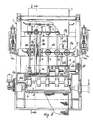
- the reference numeral 1 indicates the bed of the expanded sheet metal production machine.
- the bed 1 has a surface 2 on which the sheet metal (L) slides. This surface terminates at the level of a backing blade 3.
- the backing blade 3 is mounted on a slide 4 horizontally slidable in the bed 2 through a distance which is limited at the end comprising the backing blade by a stop member 5.
- Rods 6 are fixed to the slide, these in practice constituting the rods of pneumatic cylinders 7 connected to a compressed air source, not shown.
- the cylinders in question are fixed to a cross-member 8 within the bed 1.
- the backing blade 10 Under the thrust of the pneumatic cylinders 7 the backing blade 10 tends to abut against the stop member 5 rigid with the bed 1.
- the backing blade 3 is designed to cooperate with a toothed blade 20 mounted in a slide 21 which can be driven with reciprocating horizontal motion by known means, not shown, and described for example in the initially stated patents.
- the slide 21 is mounted in a ram 22 mobile vertically under the control of crank mechanisms 23, which are not shown or described. An example thereof is described in the initially cited patents.
- the toothed blade 20 is therefore able to undergo both vertical motion away from and towards the underlying backing blade 3, and horizontal motion.
- the feed device 13 comprises an upper cross-member 13a connecting together a pair of side members 13b.
- a second cross-member connects the two side members 13b together below the slide surface 2.
- the second cross-member upperly carries a plate 13d for example consisting of or covered with a friction material, which penetrates into an aperture 2a in the surface 2 and has its upper face substantially in line with the slide surface 2.
- the second cross-member carries sleeves 13e in which bushes or ball bearings 13f are mounted to allow linear movement.
- Guide rods 13g pass through the sleeves 13e and are fixed to inner transverse walls 1a of the bed 1.
- the threaded rod 13n of a double-acting pneumatic cylinder 13o is fixed to the base of each of the two side members 13b by a bracket 13m.
- the rod 13n is guided axially in supports 13p rigid with the bed 1, and between the two supports carries a threaded ring nut 13q for adjusting the feed stroke of the feed device 13, as described hereinafter.
- the brake 12, which acts on the sheet L alternately with the programmed feed device 13, comprises a brake shoe 12a of high coefficient of friction provided at the lower end of a plate 12b from which there rises a series of supports 12c.
- the supports 12c are mounted on a shaft 12d comprising cams 12e, the rotation of which enables the shoe 12a to be applied to the underlying sheet metal L or to be withdrawn from it.
- the shaft 12d carries two arms 12f at its two ends. Each arm is hinged to a double acting pneumatic cylinder 12g hinged at its based to the bed 1.
- the sheet flattener 11 lowerly comprises a plate 11a rigid with supports 11b traversed by a camshaft 11c driven by gears 11d and a rack (not visible on the figures) by means of a double-acting pneumatic cylinder 11e.
- This cylinder controls the raising and lowering of the plate 11a from and towards the sheet metal L.
- the machine is provided with a control unit 40.
- the operator sets on said control unit the parameters of the expanded sheet metal to be obtained. Data representing the machine conditions are continuously fed to this unit. These data are compared with the preset parameters. When coincidence is verified, signals are emitted to modify the machine operating conditions. Said data are provided by sensors.
- first sensor S1 see Figure 3
- end-of-travel sensors S2, S3 for the feed device 13.
- the operator sets, for example, the number of strokes which the feed device 13 must effect before a given event occurs.
- a metal sheet A of a given length is to be produced, such as that shown in Figure 4, ie having a front end portion A1 and a rear end portion A2 which are equal and without stretch, ie free of apertures 50.
- the stretching operation therefore concerns only the intermediate portion A3 of the sheet.
- the toothed blade 20 and the backing blade 3 mounted on the machine are correct for the particular processing to which the metal sheet A is to be subjected.
- the operator places the sheet A on the slide surface 2, which is such as to allow easy sliding of the sheet, for example because it carries a very light film of lubricant, because it is of suitable surface finish, or because it combines these two aspects.
- this pitch being indicated by P in Figure 4, he correctly positions the ring nuts 13q of the feed devices.
- the distance between these ring nuts and the left hand support 13p ( Figure 3) of the devices 13 is equal to this pitch. If the front and rear end portions A1, A2 of the metal sheet correspond for example to five pitches P, the operator sets this parameter on the control unit 40. This means that the blade 20 must remain at rest and distant from the backing blade 3 through five initial feed pitch movements and five final feed pitch movements.
- this value is also set on the control unit 40. This means that stretching of the metal sheet A commences after the five initial pitch movements (corresponding to the portion A1), this stretching ceasing when there are five final pitch movements to go (corresponding to the portion A2).
- the operator places the metal sheet on the slide surface 2 taking care that at least a given portion of the sheet lies within the feed device 13.
- this device On starting the machine, only this device operates. Its shoe locks the sheet A against the plate 13d by virtue of pressure being supplied to the double-acting cylinders 13h which control it. Pressure is then applied to the cylinders 13o so that the sheet A moves forward (arrow X of Figure 3) through one pitch towards the backing blade 3.
- the sensor S2 positioned thereat transmits this information to the control unit 40 which causes the shoe 131 to rise and the device 13 to return to its initial position.
- the other end-of-travel sensor S3 causes the sheet A to undergo a further forward movement.
- the sensor S1 acts to cause the feed device to return to its initial position even if it has not effected a whole pitch movement.
- the feed device is enabled for five pitch movements (to obtain the portion A1) without the blade 20 being brought into operation, ie without being driven to produce the stretching effect by cooperation with the backing blade 3.
- the operating conditions are modified in the sense that the blade 20 is operated to produce the stretching stage lasting for the scheduled one hundred pitch movements.
- the sheet A moves through one pitch at a time by the action of the device 13 in the manner described, the brake 12 is applied and the blade 20 lowered, followed by disengagement and return of the feed device 13.
- the control unit releases the brake 12 and halts the blade 20 in a position distant from the backing blade 3 to commence a stage corrresponding to that described in relation to the portion A1, ie to obtain the rear end portion A2.
- the sensor S1 the machine stops.
- the intitial part of the strip is passed under the feed device 13.
- the machine is started.
- the device feeds the strip as far as the backing blade 3 with the set pitch movement.
- the sensor S1 activates the backing blade.
- the stretching operation thus begins.
- the control unit 40 halts the feed movement and causes the brake to act, but keeps the toothed blade 20 moving for one more descent stroke. As this further descent takes place after the toothed blade 20 has undergone a horizontal movement, a totally stretched sheet is cut from the strip. Said operation then recommences.
- the sensors S1, S2 and 3 can be chosen from a large number of well known types such as of photoelectric cell or photodiode type or proximity sensors for example of magnetic, inductive, capacitive or other type. Their signals can be counted and compared with the preset data by using electronic circuits widely known in the control field. Based on the data received, the control unit 40 which comprises said circuits controls solenoid valves, for example of two or three-way and/or reversing type, for the feed and discharge of air to and from the pneumatic cylinders.
- solenoid valves for example of two or three-way and/or reversing type
Landscapes
- Engineering & Computer Science (AREA)
- Mechanical Engineering (AREA)
- Shaping By String And By Release Of Stress In Plastics And The Like (AREA)
- Laminated Bodies (AREA)
Applications Claiming Priority (2)
| Application Number | Priority Date | Filing Date | Title |
|---|---|---|---|
| IT294288 | 1988-06-10 | ||
| IT02942/88A IT1220269B (it) | 1988-06-10 | 1988-06-10 | Perfezionamenti alle macchine per produrre lamiera stirata |
Publications (2)
| Publication Number | Publication Date |
|---|---|
| EP0345489A2 true EP0345489A2 (de) | 1989-12-13 |
| EP0345489A3 EP0345489A3 (de) | 1990-10-10 |
Family
ID=11104124
Family Applications (1)
| Application Number | Title | Priority Date | Filing Date |
|---|---|---|---|
| EP19890108709 Withdrawn EP0345489A3 (de) | 1988-06-10 | 1989-05-16 | Vorrichtungen zur Herstellung von Streckmetall |
Country Status (2)
| Country | Link |
|---|---|
| EP (1) | EP0345489A3 (de) |
| IT (1) | IT1220269B (de) |
Cited By (2)
| Publication number | Priority date | Publication date | Assignee | Title |
|---|---|---|---|---|
| US5063647A (en) * | 1988-07-29 | 1991-11-12 | Hans Schmidlin | Method for handling and further processing a honeycomb band |
| CN110125693A (zh) * | 2019-05-22 | 2019-08-16 | 肇庆科达机械制造有限公司 | 一种大规格高合金自动化生产线 |
Family Cites Families (3)
| Publication number | Priority date | Publication date | Assignee | Title |
|---|---|---|---|---|
| US3011244A (en) * | 1959-03-16 | 1961-12-05 | American Brake Shoe Co | Apparatus for producing expanded metal |
| US3512438A (en) * | 1967-12-11 | 1970-05-19 | James T Burdge | Strip stock feeding system for punch press |
| US4329897A (en) * | 1979-03-13 | 1982-05-18 | Scribner Albert W | Control system for pneumatic punch press feeders |
-
1988
- 1988-06-10 IT IT02942/88A patent/IT1220269B/it active
-
1989
- 1989-05-16 EP EP19890108709 patent/EP0345489A3/de not_active Withdrawn
Cited By (2)
| Publication number | Priority date | Publication date | Assignee | Title |
|---|---|---|---|---|
| US5063647A (en) * | 1988-07-29 | 1991-11-12 | Hans Schmidlin | Method for handling and further processing a honeycomb band |
| CN110125693A (zh) * | 2019-05-22 | 2019-08-16 | 肇庆科达机械制造有限公司 | 一种大规格高合金自动化生产线 |
Also Published As
| Publication number | Publication date |
|---|---|
| EP0345489A3 (de) | 1990-10-10 |
| IT8802942A0 (it) | 1988-06-10 |
| IT1220269B (it) | 1990-06-06 |
Similar Documents
| Publication | Publication Date | Title |
|---|---|---|
| DE69320015T2 (de) | Vorrichtung zur Krümmung von Nadeln mit automatischer Zuführung | |
| EP0980314B1 (de) | Verfahren und vorrichtung zur montage biegsamer platten, z.b. druckplatten | |
| EP0613739B1 (de) | Biegverfahren und -gerät | |
| DE2247234A1 (de) | Stoffwendevorrichtung | |
| DE2919551A1 (de) | Anordnung mit einer numerisch gesteuerten revolverstanze und einer automatischen werkstueckzufuhreinrichtung | |
| US4580710A (en) | Stock feeder with hydraulic shock absorber | |
| US4090703A (en) | Feeding apparatus for sheet material | |
| KR910007926B1 (ko) | 헤밍장치 | |
| EP0345489A2 (de) | Vorrichtungen zur Herstellung von Streckmetall | |
| DE69621257T2 (de) | Längenverstellbares fördersystem | |
| US5689986A (en) | Apparatus and method for prenotching and dimensionally measuring a roll formed part | |
| DE3881374T2 (de) | Stossabsorbierender Werkstückträger für Biegemaschinen. | |
| US4879894A (en) | Press with movable workpiece support carrier | |
| DE2346797A1 (de) | Automatisches richtverfahren und richtpresse dafuer mit einer richtstelle | |
| DE69321787T2 (de) | Verfahren und Vorrichtung zur Formung von gekrümmten Nadeln | |
| GB1384400A (en) | Stamping presses | |
| US3963161A (en) | Sheet feeder for cupping press | |
| DE10053542A1 (de) | Verfahren zum Herstellen einer Bogenentladungsröhre | |
| DE2303659C3 (de) | Vorrichtung zum automatischen Zu- oder Abführen von Werkstucken zu bzw. aus Werkzeugmaschinen | |
| DE102018117925A1 (de) | Nähmaschine | |
| DE69721949T3 (de) | Presse zum Formen von hergestellten Gegenständen aus Ton | |
| US3599468A (en) | Wire drawing and feeding apparatus | |
| CN2270577Y (zh) | 金属眼镜框弯框机 | |
| EP0321602A1 (de) | Zangenvorschubgerät mit pneumatisch oder hydraulisch angetriebenen Kurbeltrieben | |
| CN219381594U (zh) | 一种塑料制品加工用压印装置 |
Legal Events
| Date | Code | Title | Description |
|---|---|---|---|
| PUAI | Public reference made under article 153(3) epc to a published international application that has entered the european phase |
Free format text: ORIGINAL CODE: 0009012 |
|
| AK | Designated contracting states |
Kind code of ref document: A2 Designated state(s): ES FR GB |
|
| PUAL | Search report despatched |
Free format text: ORIGINAL CODE: 0009013 |
|
| AK | Designated contracting states |
Kind code of ref document: A3 Designated state(s): ES FR GB |
|
| STAA | Information on the status of an ep patent application or granted ep patent |
Free format text: STATUS: THE APPLICATION IS DEEMED TO BE WITHDRAWN |
|
| 18D | Application deemed to be withdrawn |
Effective date: 19910411 |