EP0344595A2 - Magnetische Drucklager - Google Patents
Magnetische Drucklager Download PDFInfo
- Publication number
- EP0344595A2 EP0344595A2 EP89109336A EP89109336A EP0344595A2 EP 0344595 A2 EP0344595 A2 EP 0344595A2 EP 89109336 A EP89109336 A EP 89109336A EP 89109336 A EP89109336 A EP 89109336A EP 0344595 A2 EP0344595 A2 EP 0344595A2
- Authority
- EP
- European Patent Office
- Prior art keywords
- shaft
- thrust
- bearing assembly
- assembly according
- ferromagnetic material
- Prior art date
- Legal status (The legal status is an assumption and is not a legal conclusion. Google has not performed a legal analysis and makes no representation as to the accuracy of the status listed.)
- Granted
Links
Images

Classifications
-
- F—MECHANICAL ENGINEERING; LIGHTING; HEATING; WEAPONS; BLASTING
- F16—ENGINEERING ELEMENTS AND UNITS; GENERAL MEASURES FOR PRODUCING AND MAINTAINING EFFECTIVE FUNCTIONING OF MACHINES OR INSTALLATIONS; THERMAL INSULATION IN GENERAL
- F16C—SHAFTS; FLEXIBLE SHAFTS; ELEMENTS OR CRANKSHAFT MECHANISMS; ROTARY BODIES OTHER THAN GEARING ELEMENTS; BEARINGS
- F16C32/00—Bearings not otherwise provided for
- F16C32/04—Bearings not otherwise provided for using magnetic or electric supporting means
- F16C32/0406—Magnetic bearings
- F16C32/044—Active magnetic bearings
- F16C32/0459—Details of the magnetic circuit
-
- F—MECHANICAL ENGINEERING; LIGHTING; HEATING; WEAPONS; BLASTING
- F16—ENGINEERING ELEMENTS AND UNITS; GENERAL MEASURES FOR PRODUCING AND MAINTAINING EFFECTIVE FUNCTIONING OF MACHINES OR INSTALLATIONS; THERMAL INSULATION IN GENERAL
- F16C—SHAFTS; FLEXIBLE SHAFTS; ELEMENTS OR CRANKSHAFT MECHANISMS; ROTARY BODIES OTHER THAN GEARING ELEMENTS; BEARINGS
- F16C32/00—Bearings not otherwise provided for
- F16C32/04—Bearings not otherwise provided for using magnetic or electric supporting means
- F16C32/0406—Magnetic bearings
- F16C32/044—Active magnetic bearings
- F16C32/0474—Active magnetic bearings for rotary movement
- F16C32/0476—Active magnetic bearings for rotary movement with active support of one degree of freedom, e.g. axial magnetic bearings
-
- F—MECHANICAL ENGINEERING; LIGHTING; HEATING; WEAPONS; BLASTING
- F16—ENGINEERING ELEMENTS AND UNITS; GENERAL MEASURES FOR PRODUCING AND MAINTAINING EFFECTIVE FUNCTIONING OF MACHINES OR INSTALLATIONS; THERMAL INSULATION IN GENERAL
- F16C—SHAFTS; FLEXIBLE SHAFTS; ELEMENTS OR CRANKSHAFT MECHANISMS; ROTARY BODIES OTHER THAN GEARING ELEMENTS; BEARINGS
- F16C2300/00—Application independent of particular apparatuses
- F16C2300/02—General use or purpose, i.e. no use, purpose, special adaptation or modification indicated or a wide variety of uses mentioned
Definitions
- the present invention relates to magnetic bearings for accepting axial thrust loads.
- the configuration is generally such that a solid, circular ferromagnetic disc, secured to a shaft, is used for the rotor of the bearing.
- Annular electromagnetic coils are generally sited on each side of and adjacent the disc and, depending upon the thrust direction, one or other of the electromagnets balances out thrust forces along the shaft axis. This is achieved by a control system which varies the current to the electromagnet in order to maintain a substantially constant gap between the magnet and disc face.
- the diameter of the disc has generally been dictated by the magnitude of the axial load which it is necessary to counteract.
- a magnetic bearing assembly has a rotatable arrangement, at least including a shaft, and, possibly, one, or two additional parts secured to the shaft, ferromagnetic material of the rotatable arrangement both provides, in relation to the shaft axis, two axially spaced, and radially extending, faces to accept thrusts along the shaft in one direction, and extends completely between the two thrust faces, and the assembly also has a magnetic circuit comprising the ferromagnetic material between the two thrust faces, and an electromagnet, the electromagnet has an annular coil and an annular, ferromagnetic core, both the coil and the core being coaxial with the shaft, the coil is located in a channel provided in the core surface opposite to the shaft, and each pole has a radially extending face opposite to, and spaced from, an individually associated thrust face of the two radially extending thrust faces.
- each thrust face may be provided, individually, by a thrust collar, either the thrust collars being machined from the shaft material, or initially separate thrust collars of ferromagnetic material being secured to the shaft.
- ferromagnetic material providing at least one of the thrust faces is tapered in the radially outward direction to reduce the mass thereof.
- At least one of the poles of the electromagnet is tapered in the radially inward direction to minimise flux leakage into the shaft.
- the bearing assembly comprises a shaft 11 which is supported by either conventional mechanical journal bearings (not shown) or radial magnetic bearings (not shown).
- the shaft has a rotor disc 12 which is shown at the shaft end but may be intermediate the shaft.
- Two stationary annular electromagnets 13 and 14 are shown.
- the magnets 13 and 14 comprise equal pole face areas 15, 16 and 17,18 together with annular coils 19,20.
- An external thrust load, "L" is applied to the shaft in the direction of the arrow.
- An axial position sensor 21 senses the axial position of the rotor disc 12 and via a known control system (not shown) the current to the coil 19 of the electro magnet 13 is varied to maintain the clearance 22 between the rotor face 23 and the face 24 of the electro magnet 13 substantially constant.
- the second electro magnet 14 only comes into operation if the direction of the applied thrust load is reversed for some reason.
- the thrust capacity of the bearing is largely dictated by the face area of the electromagnets which in turn dictates the diameter of the rotor disc 12. Where both the axial thrust requirement and the rotational speeds are high the stresses generated at the disc periphery may exceed the strength of the disc material and cause it to burst.
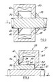
- FIG 2 shows a magnetic thrust bearing according to the present invention and which overcomes the disadvantages of the prior art thrust bearing.
- the bearing assembly shown generally at 30 comprises a shaft 31 having two collars 32,33 either machined from the shaft material as shown in Figure 2, or attached thereto as shown in Figure 3.
- the shaft is made from a ferromagnetic material such as ferritic stainless steel.
- An annular channel-section electromagnet 34 having pole faces 35 and 36 and an annular coil 37 surrounds the shaft 31.
- the external applied thrust load, "L" is in the direction of the arrow.
- the total electromagnet pole face areas may be equal to that shown in Figure 1 for electromagnet 13.
- the thrust load is accepted by two rotor discs or collars 32 and 33 of considerably smaller diameter than the disc 12.
- the available volume for the coil 37 is also considerably greater than in the electromagnet 13. This allows lower power to be used for any given force to be generated and thus results in less heat to be dissipated.
- the circuit for the magnet flux flows through the shaft surface since it is ferromagnetic.
- Figure 3 shows a modification of the bearing of Figure 2, the modifications improving the efficiency of the bearing.
- the thrust collars 32 and 33 have an annular taper 40,41 to reduce still further the forces generated during rotation by reduction in the mass at the outer peripheries of the collars.
- the radially inwardly directed pole pieces 42 and 43 of the electromagnet 34 have an annular tapers 44,45. This minimises flux leakage, which is equivalent to a reduction in the thrust capacity, directly from the faces 38 and 39 ( Figure 2) into the shaft.
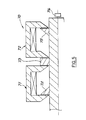
- FIG 4 shows an alternative embodiment 50 where, for example, the shaft 51 may be magnetically non-permeable.
- a ferromagnetic, annular sleeve 52 is attached to the shaft.
- the sleeve has a rear face 53 to co-operate with a pole face 54 of an electromagnet 55 and a radially extending flange or disc 56 with an annular taper 57 to minimise generated forces during rotation.
- the flange face 58 co-operates with the second pole face 59 of the electromagnet 55 the magnetic flux flowing through the axially extending cylindrical body 60 of the sleeve 52 to complete the magnetic circuit.
- the pole pieces 61 and 62 again have annular tapers 63 and 64 to minimise flux leakage in undesirable directions.
- Figure 5 shows an arrangement 70 where the reversal of the direction of the applied thrust load may be accommodated.
- the arrangement comprises two electromagnets 71 and 72 which both act upon a common thrust collar 73 depending upon the thrust direction. Collars 74 and 75 are also provided and which are dedicated to a particular thrust direction.
- a position sensor 76 allied to known control circuitry is also provided.
Landscapes
- Engineering & Computer Science (AREA)
- General Engineering & Computer Science (AREA)
- Mechanical Engineering (AREA)
- Magnetic Bearings And Hydrostatic Bearings (AREA)
Applications Claiming Priority (2)
| Application Number | Priority Date | Filing Date | Title |
|---|---|---|---|
| GB8813019 | 1988-06-02 | ||
| GB8813019A GB2219357B (en) | 1988-06-02 | 1988-06-02 | Magnetic thrust bearings |
Publications (3)
| Publication Number | Publication Date |
|---|---|
| EP0344595A2 true EP0344595A2 (de) | 1989-12-06 |
| EP0344595A3 EP0344595A3 (en) | 1990-10-17 |
| EP0344595B1 EP0344595B1 (de) | 1994-03-16 |
Family
ID=10637923
Family Applications (1)
| Application Number | Title | Priority Date | Filing Date |
|---|---|---|---|
| EP89109336A Expired - Lifetime EP0344595B1 (de) | 1988-06-02 | 1989-05-24 | Magnetische Drucklager |
Country Status (7)
| Country | Link |
|---|---|
| US (1) | US5101130A (de) |
| EP (1) | EP0344595B1 (de) |
| JP (1) | JP2886891B2 (de) |
| KR (1) | KR900000607A (de) |
| DE (1) | DE68913810T2 (de) |
| GB (1) | GB2219357B (de) |
| YU (1) | YU114089A (de) |
Cited By (2)
| Publication number | Priority date | Publication date | Assignee | Title |
|---|---|---|---|---|
| WO2000041290A1 (en) * | 1998-12-30 | 2000-07-13 | High Speed Tech Oy Ltd. | Magnetic circuit structure |
| CN113346671A (zh) * | 2020-12-23 | 2021-09-03 | 苏州苏磁智能科技有限公司 | 一种磁悬浮装置、磁悬浮电机、透平电机系统 |
Families Citing this family (12)
| Publication number | Priority date | Publication date | Assignee | Title |
|---|---|---|---|---|
| JP2946793B2 (ja) * | 1991-03-19 | 1999-09-06 | ブラザー工業株式会社 | 光偏向器 |
| GB2258699A (en) * | 1991-08-10 | 1993-02-17 | Rolls Royce Business Ventures | Shaft bearing arrangement |
| GB2269862B (en) * | 1992-08-22 | 1996-05-08 | Glacier Metal Co Ltd | Electromagnetic bearing arrangement |
| FR2751028B1 (fr) * | 1996-07-10 | 1998-10-23 | Sames Sa | Turbine a suspension magnetofluidique |
| US5789838A (en) * | 1996-10-09 | 1998-08-04 | Satcon Technology Corporation | Three-axis force actuator for a magnetic bearing |
| JP3924844B2 (ja) * | 1997-05-30 | 2007-06-06 | 石川島播磨重工業株式会社 | ターボチャージャのスラスト軸受構造 |
| US6008558A (en) * | 1998-09-17 | 1999-12-28 | Sundstrand Corporation | L-shaped magnetic thrust bearing |
| US8314527B2 (en) * | 2007-06-20 | 2012-11-20 | Beacon Power, Llc | Advanced flywheel and method |
| US7679247B2 (en) * | 2007-06-20 | 2010-03-16 | Beacon Power Corporation | Lift magnet mechanism for flywheel power storage systems |
| US9209663B2 (en) * | 2012-10-08 | 2015-12-08 | Active Power, Inc. | Apparatus and methods for passive magnetic reduction of thrust force in rotating machines |
| US8963393B2 (en) | 2012-12-18 | 2015-02-24 | Abb Research Ltd. | Magnetic thrust bearings |
| KR102366588B1 (ko) * | 2020-02-17 | 2022-02-22 | 엘지전자 주식회사 | 압축기 및 이를 포함하는 칠러 |
Family Cites Families (19)
| Publication number | Priority date | Publication date | Assignee | Title |
|---|---|---|---|---|
| FR1347020A (fr) * | 1962-08-22 | 1963-12-27 | Commissariat Energie Atomique | Machine tournante |
| DE1933031C3 (de) * | 1969-06-30 | 1978-10-26 | Karl 5170 Juelich Boden | Magnetische Lagerung |
| US3865442A (en) * | 1970-12-22 | 1975-02-11 | Nasa | Magnetic bearing |
| US3791704A (en) * | 1971-08-06 | 1974-02-12 | Cambridge Thermionic Corp | Trimming apparatus for magnetic suspension systems |
| DE2213470C3 (de) * | 1972-03-20 | 1988-12-01 | Padana AG, Zug | Magnetisches Lager |
| US3909082A (en) * | 1972-08-30 | 1975-09-30 | Hitachi Ltd | Magnetic bearing devices |
| DE2355104A1 (de) * | 1973-11-03 | 1975-05-15 | Bbc Brown Boveri & Cie | Elektromagnetisches axiallager |
| JPS5226578B2 (de) * | 1974-02-08 | 1977-07-14 | ||
| FR2377549A1 (fr) * | 1977-01-12 | 1978-08-11 | Europ Propulsion | Montage de rotor court de grand diametre |
| JPS5765417A (en) * | 1980-10-09 | 1982-04-21 | Seiko Instr & Electronics Ltd | Magnetic bearing |
| JPS5828014A (ja) * | 1981-08-12 | 1983-02-18 | Fuji Electric Co Ltd | 磁気軸受の励磁調整装置 |
| SU1190113A1 (ru) * | 1982-05-06 | 1985-11-07 | Николаевский Ордена Трудового Красного Знамени Кораблестроительный Институт Им.Адм.С.О.Макарова | Управл емый динамический виброгаситель |
| JPS5919714A (ja) * | 1982-07-26 | 1984-02-01 | Toshiba Corp | 磁気軸受装置 |
| US4527802A (en) * | 1983-03-21 | 1985-07-09 | Mechanical Technology Incorporated | Integral magnetic fluid centrifugal high speed gas seal and method |
| US4652820A (en) * | 1983-03-23 | 1987-03-24 | North American Philips Corporation | Combined position sensor and magnetic motor or bearing |
| JPS61175314A (ja) * | 1985-01-31 | 1986-08-07 | Natl Aerospace Lab | 磁気軸受 |
| US4710656A (en) * | 1986-12-03 | 1987-12-01 | Studer Philip A | Spring neutralized magnetic vibration isolator |
| US4956571A (en) * | 1989-03-01 | 1990-09-11 | Mpb Corporation | Superconducting magnetic bearing |
| JP4929217B2 (ja) | 2008-03-28 | 2012-05-09 | 三菱重工業株式会社 | ガスタービンおよびガスタービンの中間軸ならびにガスタービン圧縮機の冷却方法 |
-
1988
- 1988-06-02 GB GB8813019A patent/GB2219357B/en not_active Expired - Lifetime
-
1989
- 1989-05-24 EP EP89109336A patent/EP0344595B1/de not_active Expired - Lifetime
- 1989-05-24 DE DE68913810T patent/DE68913810T2/de not_active Expired - Fee Related
- 1989-05-29 KR KR1019890007147A patent/KR900000607A/ko not_active Abandoned
- 1989-05-30 US US07/358,140 patent/US5101130A/en not_active Expired - Lifetime
- 1989-05-31 JP JP1136278A patent/JP2886891B2/ja not_active Expired - Fee Related
- 1989-06-02 YU YU01140/89A patent/YU114089A/xx unknown
Cited By (2)
| Publication number | Priority date | Publication date | Assignee | Title |
|---|---|---|---|---|
| WO2000041290A1 (en) * | 1998-12-30 | 2000-07-13 | High Speed Tech Oy Ltd. | Magnetic circuit structure |
| CN113346671A (zh) * | 2020-12-23 | 2021-09-03 | 苏州苏磁智能科技有限公司 | 一种磁悬浮装置、磁悬浮电机、透平电机系统 |
Also Published As
| Publication number | Publication date |
|---|---|
| YU114089A (en) | 1991-10-31 |
| US5101130A (en) | 1992-03-31 |
| DE68913810T2 (de) | 1994-10-27 |
| JPH0226311A (ja) | 1990-01-29 |
| EP0344595A3 (en) | 1990-10-17 |
| EP0344595B1 (de) | 1994-03-16 |
| DE68913810D1 (de) | 1994-04-21 |
| GB8813019D0 (en) | 1988-07-06 |
| GB2219357B (en) | 1992-05-27 |
| GB2219357A (en) | 1989-12-06 |
| JP2886891B2 (ja) | 1999-04-26 |
| KR900000607A (ko) | 1990-01-30 |
Similar Documents
| Publication | Publication Date | Title |
|---|---|---|
| US6121704A (en) | Magnetic bearing | |
| US5729065A (en) | Magnetic bearing cell with rotor and stator | |
| EP0344595B1 (de) | Magnetische Drucklager | |
| US6359357B1 (en) | Combination radial and thrust magnetic bearing | |
| SU1711681A3 (ru) | Магнитный опорный узел ротора с посто нными магнитами дл воспри ти радиальных усилий на опорах | |
| EP0191225B1 (de) | Magnetlager | |
| JP2826156B2 (ja) | スピンドルモータ | |
| EP0584846B1 (de) | Elektromagnetische Lagervorrichtung | |
| US5811904A (en) | Permanent magnet dynamo electric machine | |
| EP0130541B1 (de) | Schwungrad-Einrichtung | |
| EP0411697B1 (de) | Magnetische Lager | |
| EP0225616B1 (de) | Elektrischer Motor | |
| US5767597A (en) | Electromagnetically biased homopolar magnetic bearing | |
| US4983870A (en) | Radial magnetic bearing | |
| US4340261A (en) | Magnetic bearing arrangement | |
| US20100127589A1 (en) | Bearing device having a shaft which is mounted magnetically such that it can rotate about an axis with respect to a stator, and having a damping apparatus | |
| US4983869A (en) | Magnetic bearing | |
| US4597613A (en) | Electromagnetic bearing | |
| CA1249321A (en) | Active radial magnetic bearing with solid rotor for damping critical frequencies | |
| EP0687827A1 (de) | Hybride Magnet/Folien-Gas-Lager | |
| US5032751A (en) | Magnetic fluid bearing | |
| EP0411696A2 (de) | Magnetisches Drucklager | |
| WO2001084693A1 (en) | Full levitation bearing system with improved passive radial magnetic bearings | |
| GB2134326A (en) | Motor for a pump | |
| EP0344596A2 (de) | Magnetische Drucklager |
Legal Events
| Date | Code | Title | Description |
|---|---|---|---|
| PUAI | Public reference made under article 153(3) epc to a published international application that has entered the european phase |
Free format text: ORIGINAL CODE: 0009012 |
|
| AK | Designated contracting states |
Kind code of ref document: A2 Designated state(s): CH DE FR IT LI SE |
|
| PUAL | Search report despatched |
Free format text: ORIGINAL CODE: 0009013 |
|
| AK | Designated contracting states |
Kind code of ref document: A3 Designated state(s): CH DE FR IT LI SE |
|
| 17P | Request for examination filed |
Effective date: 19910326 |
|
| 17Q | First examination report despatched |
Effective date: 19920908 |
|
| ITF | It: translation for a ep patent filed | ||
| GRAA | (expected) grant |
Free format text: ORIGINAL CODE: 0009210 |
|
| AK | Designated contracting states |
Kind code of ref document: B1 Designated state(s): CH DE FR IT LI SE |
|
| REF | Corresponds to: |
Ref document number: 68913810 Country of ref document: DE Date of ref document: 19940421 |
|
| ET | Fr: translation filed | ||
| PLBE | No opposition filed within time limit |
Free format text: ORIGINAL CODE: 0009261 |
|
| STAA | Information on the status of an ep patent application or granted ep patent |
Free format text: STATUS: NO OPPOSITION FILED WITHIN TIME LIMIT |
|
| EAL | Se: european patent in force in sweden |
Ref document number: 89109336.1 |
|
| 26N | No opposition filed | ||
| REG | Reference to a national code |
Ref country code: CH Ref legal event code: PUE Owner name: FEDERAL-MOGUL ENGINEERING LIMITED TRANSFER- DELAWA Ref country code: CH Ref legal event code: PFA Free format text: THE GLACIER METAL COMPANY LIMITED TRANSFER- FEDERAL-MOGUL ENGINEERING LIMITED |
|
| REG | Reference to a national code |
Ref country code: FR Ref legal event code: TP Ref country code: FR Ref legal event code: CD Ref country code: FR Ref legal event code: CA |
|
| PGFP | Annual fee paid to national office [announced via postgrant information from national office to epo] |
Ref country code: FR Payment date: 20040513 Year of fee payment: 16 |
|
| PGFP | Annual fee paid to national office [announced via postgrant information from national office to epo] |
Ref country code: CH Payment date: 20040519 Year of fee payment: 16 |
|
| PGFP | Annual fee paid to national office [announced via postgrant information from national office to epo] |
Ref country code: DE Payment date: 20040520 Year of fee payment: 16 |
|
| PGFP | Annual fee paid to national office [announced via postgrant information from national office to epo] |
Ref country code: SE Payment date: 20040521 Year of fee payment: 16 |
|
| PG25 | Lapsed in a contracting state [announced via postgrant information from national office to epo] |
Ref country code: IT Free format text: LAPSE BECAUSE OF NON-PAYMENT OF DUE FEES;WARNING: LAPSES OF ITALIAN PATENTS WITH EFFECTIVE DATE BEFORE 2007 MAY HAVE OCCURRED AT ANY TIME BEFORE 2007. THE CORRECT EFFECTIVE DATE MAY BE DIFFERENT FROM THE ONE RECORDED. Effective date: 20050524 |
|
| PG25 | Lapsed in a contracting state [announced via postgrant information from national office to epo] |
Ref country code: SE Free format text: LAPSE BECAUSE OF NON-PAYMENT OF DUE FEES Effective date: 20050525 |
|
| PG25 | Lapsed in a contracting state [announced via postgrant information from national office to epo] |
Ref country code: LI Free format text: LAPSE BECAUSE OF NON-PAYMENT OF DUE FEES Effective date: 20050531 Ref country code: CH Free format text: LAPSE BECAUSE OF NON-PAYMENT OF DUE FEES Effective date: 20050531 |
|
| PG25 | Lapsed in a contracting state [announced via postgrant information from national office to epo] |
Ref country code: DE Free format text: LAPSE BECAUSE OF NON-PAYMENT OF DUE FEES Effective date: 20051201 |
|
| REG | Reference to a national code |
Ref country code: CH Ref legal event code: PL |
|
| EUG | Se: european patent has lapsed | ||
| PG25 | Lapsed in a contracting state [announced via postgrant information from national office to epo] |
Ref country code: FR Free format text: LAPSE BECAUSE OF NON-PAYMENT OF DUE FEES Effective date: 20060131 |
|
| REG | Reference to a national code |
Ref country code: FR Ref legal event code: ST Effective date: 20060131 |