EP0344079A1 - Landmaschine mit mindestens einem während der Arbeit angetriebenen Rechrad - Google Patents
Landmaschine mit mindestens einem während der Arbeit angetriebenen Rechrad Download PDFInfo
- Publication number
- EP0344079A1 EP0344079A1 EP89440034A EP89440034A EP0344079A1 EP 0344079 A1 EP0344079 A1 EP 0344079A1 EP 89440034 A EP89440034 A EP 89440034A EP 89440034 A EP89440034 A EP 89440034A EP 0344079 A1 EP0344079 A1 EP 0344079A1
- Authority
- EP
- European Patent Office
- Prior art keywords
- machine according
- housing
- shaft
- toothed wheel
- rotation
- Prior art date
- Legal status (The legal status is an assumption and is not a legal conclusion. Google has not performed a legal analysis and makes no representation as to the accuracy of the status listed.)
- Granted
Links
- 230000005540 biological transmission Effects 0.000 claims description 18
- 230000008878 coupling Effects 0.000 description 3
- 238000010168 coupling process Methods 0.000 description 3
- 238000005859 coupling reaction Methods 0.000 description 3
- 239000004459 forage Substances 0.000 description 2
- 230000009467 reduction Effects 0.000 description 2
- 230000008901 benefit Effects 0.000 description 1
- 230000008859 change Effects 0.000 description 1
- 238000006073 displacement reaction Methods 0.000 description 1
- 230000004048 modification Effects 0.000 description 1
- 238000012986 modification Methods 0.000 description 1
- 238000006467 substitution reaction Methods 0.000 description 1
Images

Classifications
-
- A—HUMAN NECESSITIES
- A01—AGRICULTURE; FORESTRY; ANIMAL HUSBANDRY; HUNTING; TRAPPING; FISHING
- A01D—HARVESTING; MOWING
- A01D78/00—Haymakers with tines moving with respect to the machine
- A01D78/08—Haymakers with tines moving with respect to the machine with tine-carrying rotary heads or wheels
- A01D78/10—Haymakers with tines moving with respect to the machine with tine-carrying rotary heads or wheels the tines rotating about a substantially vertical axis
- A01D78/1057—Drive mechanisms
-
- A—HUMAN NECESSITIES
- A01—AGRICULTURE; FORESTRY; ANIMAL HUSBANDRY; HUNTING; TRAPPING; FISHING
- A01D—HARVESTING; MOWING
- A01D69/00—Driving mechanisms or parts thereof for harvesters or mowers
-
- Y—GENERAL TAGGING OF NEW TECHNOLOGICAL DEVELOPMENTS; GENERAL TAGGING OF CROSS-SECTIONAL TECHNOLOGIES SPANNING OVER SEVERAL SECTIONS OF THE IPC; TECHNICAL SUBJECTS COVERED BY FORMER USPC CROSS-REFERENCE ART COLLECTIONS [XRACs] AND DIGESTS
- Y10—TECHNICAL SUBJECTS COVERED BY FORMER USPC
- Y10S—TECHNICAL SUBJECTS COVERED BY FORMER USPC CROSS-REFERENCE ART COLLECTIONS [XRACs] AND DIGESTS
- Y10S56/00—Harvesters
- Y10S56/06—Clutches and gearing
-
- Y—GENERAL TAGGING OF NEW TECHNOLOGICAL DEVELOPMENTS; GENERAL TAGGING OF CROSS-SECTIONAL TECHNOLOGIES SPANNING OVER SEVERAL SECTIONS OF THE IPC; TECHNICAL SUBJECTS COVERED BY FORMER USPC CROSS-REFERENCE ART COLLECTIONS [XRACs] AND DIGESTS
- Y10—TECHNICAL SUBJECTS COVERED BY FORMER USPC
- Y10T—TECHNICAL SUBJECTS COVERED BY FORMER US CLASSIFICATION
- Y10T74/00—Machine element or mechanism
- Y10T74/19—Gearing
- Y10T74/19023—Plural power paths to and/or from gearing
- Y10T74/19028—Alternate input connections single hand crank
-
- Y—GENERAL TAGGING OF NEW TECHNOLOGICAL DEVELOPMENTS; GENERAL TAGGING OF CROSS-SECTIONAL TECHNOLOGIES SPANNING OVER SEVERAL SECTIONS OF THE IPC; TECHNICAL SUBJECTS COVERED BY FORMER USPC CROSS-REFERENCE ART COLLECTIONS [XRACs] AND DIGESTS
- Y10—TECHNICAL SUBJECTS COVERED BY FORMER USPC
- Y10T—TECHNICAL SUBJECTS COVERED BY FORMER US CLASSIFICATION
- Y10T74/00—Machine element or mechanism
- Y10T74/19—Gearing
- Y10T74/19023—Plural power paths to and/or from gearing
- Y10T74/19051—Single driven plural drives
- Y10T74/19056—Parallel
Definitions
- the present invention relates to an agricultural machine in particular for haymaking, comprising in particular a chassis supporting at least one rotor driven in rotation during work around a substantially vertical axis, which drive is carried out from the shaft of tractor PTO.
- Machines of this kind which are equipped with a rotor for swathing plants lying on the ground must increasingly be able to be coupled both at the front and at the rear of the tractors.
- a second machine can be coupled, for example a baler or forage harvester, at the rear in order to carry out two operations simultaneously.
- Another advantage of mounting the front rake is that the tractor wheels do not pass over the spread forage.
- the present invention in particular aims to remedy these drawbacks. It must in particular offer at a lower cost a machine with at least one rotor that can be driven in the right direction and at the right speed from any front or rear PTO shaft of a tractor.
- an important characteristic of the invention consists in that the machine is equipped with a drive box containing two toothed wheels which mesh with each other and have different diameters and numbers of teeth and each of which is linked to a shaft extending out of the housing and capable of being driven from the power take-off shaft of the tractor, said housing containing a third toothed wheel which is provided with an output shaft which can be connected to the rotor, which third gear can be brought into engagement with one or the other of the two above-mentioned toothed wheels.
- the two sprockets which can be driven from the PTO shaft have numbers of teeth which differ in a ratio such as when the speed of rotation of one is of the order of 1000 rpm the speed of rotation of the other is about 540 rpm.
- This arrangement makes it possible to correctly animate the rotor or rotors of the machine, whether it is at the front or at the rear of the tractor, by using only one housing with only three gears. It is in fact possible to keep practically the same speed of rotation of the third toothed wheel and consequently of the rotor (s), by connecting the PTO shaft of the tractor to the input shaft of the toothed wheel having the smallest diameter if it rotates at 1000 rpm and vice versa, at the input shaft of the toothed wheel which has the largest diameter if it rotates at 540 rpm.
- a torque limiter is provided on the transmission shaft connecting the output shaft of the third toothed wheel of the aforementioned rotor housing. Thanks to this arrangement, the limiter does not undergo any change in direction or speed of rotation which could alter its operation.
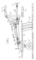
- This machine comprises in particular a frame (1) in the form of a beam. At one of its ends, said chassis carries a coupling bridge (2) used to couple the machine to the lifting device (3) of a drive tractor not shown. The connection between the machine and the tractor is ensured by means of connecting rods (4). This coupling can be done on the rear side or on the front side of the tractor if the latter is equipped accordingly.
- the chassis (1) carries a rotor (5) which can be driven in rotation during work around a central axis (6) substantially vertical.
- This axis (6) is linked to the chassis (1) and carries at its lower end support rollers (7) which roll on the ground at least during work.
- the rotor (5) consists of a rotary hub (8) which carries arms (9) which extend outwards.
- Each of these arms (9) carries tools in the form of forks (10) which move the plants lying on the ground.
- Said arms (9) also comprise, in a manner known per se at their ends situated in the hub (8), cranks provided with rollers which move in a control cam linked to the central axis (6).
- the track of the rollers in this cam is such that, on the front part of their trajectory, the forks (10) are directed downwards and gather the plants and that, on the lateral part of their trajectory, they rise and deposit the plants in the form of a swath.
- control cam can be rotated on or with the central axis (6) depending on the direction of movement. This makes it possible to adjust the control of the arms so that the part of the trajectory on which their tools (10) are directed towards the arm is always at the front - seen in the direction of movement -.
- the rotor (5) is driven in rotation from the PTO shaft (11) of the tractor.
- the transmission means which go from said shaft (11) to the rotor (5) are partially housed in the chassis (1).
- These means comprise a transmission box (12) which is screwed onto the chassis (1).
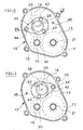
- this box (12) is constituted by two walls (13, 14) in the form of covers which are assembled by means of bolts (15). It contains three cogwheels (16, 17, 18). Two of these wheels (16 and 17) are located side by side and mesh with each other.
- the toothed wheel (16) has sixteen teeth (19) and the other toothed wheel (17) has twenty nine teeth (19).
- This ratio was chosen because it allows to keep the speed given by the PTO shaft (11) if it is 540 rpm or to reduce it to this value if the speed of the shaft ( 11) is 1000 rpm.
- Other ratios could be chosen if the power take-off shafts were to rotate at speeds other than those mentioned above. Likewise, other ratios could be chosen if the two speeds of the PTO shafts were to be reduced to another speed for the rotor drive.
- Each of these two toothed wheels (16, 17) is linked to a drive shaft (20, 21) extending out of the housing (12). These shafts (20 and 21) are guided in rotation in bores provided in the walls (13 and 14) by means of ball bearings. The end of each shaft (20 and 21) which is located outside the housing (12) can be connected to the PTO shaft (11) of the tractor by means of a cardan shaft (22).
- the third gear (18) is located above the other two wheels (16 and 17). It comprises an output shaft (23) which extends out of the housing (12) on the side opposite to that on which the shafts (20 and 21) are located.
- This output shaft (23) is connected to the rotor (5) by means of a transmission shaft (24) comprising cardan joints (25) so as to be articulated.
- the end of the transmission shaft (24) which is directed towards the rotor (5) has a pinion (26) which cooperates with a ring (27) integral with the hub (8) of the rotor (5).
- the ratio between the pinion (26) and the crown (27) ultimately determines the speed of rotation of the rotor (5).
- Said third toothed wheel (18) can be brought into engagement with one or the other of the two aforementioned two wheels (16 and 17) (see Figures 2 and 3). For this it can be tilted by about 180 ° around a geometric axis (28) eccentric with respect to its geometric axis of rotation (29). As is apparent in particular from FIGS. 4 and 5, it is made integral with the output shaft (23) by a key (30).
- This shaft (23) is mounted by means of ball bearings (31) in bores (32 and 33) of a housing (34).
- the latter consists of two rings (35 and 36) which are themselves guided in rotation in bores (37 and 38) provided in the walls (13 and 14).
- the housing (34) also includes an operating lever (42) which is located outside the housing (12). This lever (42) is fixed to the ring (35) by means of two screws (43). There is additionally provided a locking screw (44) which makes it possible to stop the lever (42) and consequently the housing (34) in the positions in which the third toothed wheel (18) is engaged with one or the other of the two toothed wheels (16 and 17).
- the wall (13) has two threaded holes (45) into which the locking screw (44) can be introduced.
- the third toothed wheel (18) which is integral with the output shaft (23) has the same diameter and the same number of teeth (19) as the wheel (17) integral with the shaft d drive (21).
- the ratio between the toothed wheel (18) and the other two toothed wheels (16 and 17) could however be different from that indicated above. This report does not intervene for the harmonization between the two regimes of PTO shafts of tractors.
- a torque limiter (46) It is connected directly to the shaft (23) and is connected to the transmission shaft (24) through the gimbal (25).
- the function of this torque limiter (46) is to interrupt the transmission of the drive movement between the PTO shaft (11) and the rotor (5) when the torque becomes too great. This can happen when an arm (9) of the rotor (5) encounters an obstacle. Thanks to the arrangement of this torque limiter (46) after the transmission unit (12) the speed at which it rotates and its direction of rotation are always the same. This allows it to be perfectly efficient both when the PTO shaft (11) of the tractor used rotates at 540 rpm or 1000 rpm.
- the machine is moved by means of the tractor.
- the rotor (5) is then rotated from the PTO shaft (11) of said tractor.
- this shaft (11) rotates at 540 rpm, it is necessary to connect the cardan shaft (22) to the drive shaft (21) of the toothed wheel (17).
- the third gear (18), the output shaft (23) and the transmission shaft (24) then also rotate at this same speed.
- the direction of rotation of said third gear (18) of the output shaft (23) of the drive shaft (24) can also be adjusted so as to rotate the rotor (5) in the appropriate direction. So if the tree of PTO (11) rotates in the direction in which the drive shaft (24) must rotate. The third gear (18) must be meshed with the gear (16) which will act as an intermediate wheel ( see figure 2). On the other hand, if the PTO shaft (11) rotates in the opposite direction to that in which the transmission shaft (24) is to rotate, the third toothed wheel (18) must be meshed with the toothed wheel (17 ). In this case, the direction of rotation is reversed (see Figure 3).
- the PTO shaft (11) of the tractor rotates at 1000 rpm, it is necessary to connect the cardan shaft (22) to the drive shaft (20) of the toothed wheel (16).
- This toothed wheel (16) then drives the third toothed wheel (18) at a speed reduced to 540 rpm.
- This drive of the third toothed wheel (18) can be done either directly or through the toothed wheel (17) and this according to the desired direction of rotation.
- the third toothed wheel (18) can be meshed with the toothed wheel (16) if one wishes to reverse the direction of rotation given by the PTO shaft (11) of the tractor or with the toothed wheel (17) if you want to keep the same direction of rotation.
- This housing (12) allows the user to adjust the speed and direction of rotation of the rotor (5) by extremely simple maneuvers so that he can drive the machine with any model of tractor.
Landscapes
- Life Sciences & Earth Sciences (AREA)
- Environmental Sciences (AREA)
- Arrangement And Driving Of Transmission Devices (AREA)
- Soil Working Implements (AREA)
Priority Applications (1)
| Application Number | Priority Date | Filing Date | Title |
|---|---|---|---|
| AT89440034T ATE84185T1 (de) | 1988-05-26 | 1989-04-27 | Landmaschine mit mindestens einem waehrend der arbeit angetriebenen rechrad. |
Applications Claiming Priority (2)
| Application Number | Priority Date | Filing Date | Title |
|---|---|---|---|
| FR8807194A FR2631775B1 (fr) | 1988-05-26 | 1988-05-26 | Machine agricole comportant au moins un rotor entraine en rotation durant le travail |
| FR8807194 | 1988-05-26 |
Publications (2)
| Publication Number | Publication Date |
|---|---|
| EP0344079A1 true EP0344079A1 (de) | 1989-11-29 |
| EP0344079B1 EP0344079B1 (de) | 1993-01-07 |
Family
ID=9366747
Family Applications (1)
| Application Number | Title | Priority Date | Filing Date |
|---|---|---|---|
| EP89440034A Expired - Lifetime EP0344079B1 (de) | 1988-05-26 | 1989-04-27 | Landmaschine mit mindestens einem während der Arbeit angetriebenen Rechrad |
Country Status (5)
| Country | Link |
|---|---|
| US (1) | US4953346A (de) |
| EP (1) | EP0344079B1 (de) |
| AT (1) | ATE84185T1 (de) |
| DE (1) | DE68904246T2 (de) |
| FR (1) | FR2631775B1 (de) |
Cited By (1)
| Publication number | Priority date | Publication date | Assignee | Title |
|---|---|---|---|---|
| US5918451A (en) * | 1996-08-06 | 1999-07-06 | Vonesch; Anthony R. | Dual lifting system for rotary hay raking machine |
Families Citing this family (11)
| Publication number | Priority date | Publication date | Assignee | Title |
|---|---|---|---|---|
| FR2678804B1 (fr) * | 1991-07-11 | 1998-09-18 | Kuhn Sa | Machine de fenaison comportant au moins une roue rateleuse, un dispositif de protection et un deflecteur reglable. |
| FR2718324B1 (fr) * | 1994-04-12 | 1996-06-14 | Kuhn Sa | Machine de fenaison, notamment un andaineur, avec au moins un dispositif d'arrêt du rotor. |
| FR2722365B1 (fr) * | 1994-07-13 | 1996-09-20 | Kuhn Sa Societe Anonyme | Machine de fenaison, notamment une andaineuse de vegetaux a bras porte-fourches commandes |
| FR2727823A1 (fr) * | 1994-12-09 | 1996-06-14 | Kuhn Sa | Machine de fenaison transposable dans plusieurs positions de travail |
| FR2740652B1 (fr) * | 1995-11-07 | 1998-01-30 | Kuhn Sa | Machine de fenaison comportant au moins un rotor d'andainage et permettant notamment une meilleure adaptation du rotor au relief du terrain |
| FR2746577B1 (fr) * | 1996-03-29 | 1998-05-29 | Kuhn Sa | Machine de fenaison comportant un dispositif de protection deplacable |
| FR2754136B1 (fr) * | 1996-10-03 | 1999-01-22 | Kuhn Sa | Machine de fenaison comportant un chassis compose de plusieurs troncons articules entre eux |
| FR2756137B1 (fr) * | 1996-11-26 | 1999-01-22 | Kuhn Sa | Machine de fenaison, notamment une andaineuse avec un deflecteur d'andainage reglage automatiquement dans differentes positions |
| US6272826B1 (en) | 1999-04-29 | 2001-08-14 | Sitrex S.R.L. | Method and apparatus for positioning a hay rake |
| US6805018B2 (en) * | 2002-09-16 | 2004-10-19 | Chester William Chattin | Portable multi-speed, multi-input, multi-output drive for power take-off's and the like |
| US9528319B1 (en) * | 2014-04-02 | 2016-12-27 | Thomas James Dostal | Ice auger reversal attachment |
Citations (10)
| Publication number | Priority date | Publication date | Assignee | Title |
|---|---|---|---|---|
| FR1337291A (fr) * | 1961-06-23 | 1963-09-13 | Fahr Ag Maschf | Faneuse remorquée par tracteur |
| CH389305A (de) * | 1960-03-18 | 1965-03-15 | Fahr Ag Maschf | Getriebe für landwirtschaftliche Maschinen |
| GB1132647A (en) * | 1965-04-13 | 1968-11-06 | Int Harvester Co | Rotary vegetation cutter |
| DE1655950A1 (de) * | 1968-02-10 | 1971-09-09 | Hermann Ziegler | Zusatzgetriebe fuer Schlepper mit Zapfwelle |
| FR2399201A1 (fr) * | 1977-08-06 | 1979-03-02 | Mengele & Soehne Masch Karl | Mecanisme de transmission fixe pour machines agricoles |
| FR2491287A1 (fr) * | 1980-10-06 | 1982-04-09 | Poettinger Ohg Alois | Ensileuse comportant un jeu d'engrenages pouvant pivoter dans differentes positions |
| EP0063531A1 (de) * | 1981-04-22 | 1982-10-27 | Kuhn S.A. | Landwirtschaftliche Maschine mit Übertragungsvorrichtung |
| FR2509117A1 (fr) * | 1981-07-09 | 1983-01-14 | Krone Bernhard Gmbh Maschf | Moissonneuse a disques avec dispositif de reglage des roues dentees d'entrainement |
| EP0155063A2 (de) * | 1984-03-15 | 1985-09-18 | C. van der Lely N.V. | Mähmaschine |
| EP0165191A1 (de) * | 1984-05-25 | 1985-12-18 | Kuhn S.A. | Landmaschine mit verbessertem Getriebe |
Family Cites Families (5)
| Publication number | Priority date | Publication date | Assignee | Title |
|---|---|---|---|---|
| DE389305C (de) | 1923-05-18 | 1924-02-02 | Wilhelm Strelow | Triebsystem fuer Wechselstromzaehler nach Ferrarisschem Prinzip |
| US2590675A (en) * | 1950-01-07 | 1952-03-25 | Albert H Bottorff | Gear power take-off drive for hammer mills |
| US3426610A (en) * | 1967-04-25 | 1969-02-11 | Neville T Henkel | Locking device for adjustable gearing |
| US4133216A (en) * | 1977-12-16 | 1979-01-09 | Vamco Machine & Tool, Inc. | Gear support assembly |
| US4601348A (en) * | 1984-08-24 | 1986-07-22 | Cox Floyd E | Reversible auger drive kit for post hole digger |
-
1988
- 1988-05-26 FR FR8807194A patent/FR2631775B1/fr not_active Expired - Fee Related
-
1989
- 1989-04-27 EP EP89440034A patent/EP0344079B1/de not_active Expired - Lifetime
- 1989-04-27 AT AT89440034T patent/ATE84185T1/de not_active IP Right Cessation
- 1989-04-27 DE DE8989440034T patent/DE68904246T2/de not_active Expired - Fee Related
- 1989-05-22 US US07/354,832 patent/US4953346A/en not_active Expired - Lifetime
Patent Citations (10)
| Publication number | Priority date | Publication date | Assignee | Title |
|---|---|---|---|---|
| CH389305A (de) * | 1960-03-18 | 1965-03-15 | Fahr Ag Maschf | Getriebe für landwirtschaftliche Maschinen |
| FR1337291A (fr) * | 1961-06-23 | 1963-09-13 | Fahr Ag Maschf | Faneuse remorquée par tracteur |
| GB1132647A (en) * | 1965-04-13 | 1968-11-06 | Int Harvester Co | Rotary vegetation cutter |
| DE1655950A1 (de) * | 1968-02-10 | 1971-09-09 | Hermann Ziegler | Zusatzgetriebe fuer Schlepper mit Zapfwelle |
| FR2399201A1 (fr) * | 1977-08-06 | 1979-03-02 | Mengele & Soehne Masch Karl | Mecanisme de transmission fixe pour machines agricoles |
| FR2491287A1 (fr) * | 1980-10-06 | 1982-04-09 | Poettinger Ohg Alois | Ensileuse comportant un jeu d'engrenages pouvant pivoter dans differentes positions |
| EP0063531A1 (de) * | 1981-04-22 | 1982-10-27 | Kuhn S.A. | Landwirtschaftliche Maschine mit Übertragungsvorrichtung |
| FR2509117A1 (fr) * | 1981-07-09 | 1983-01-14 | Krone Bernhard Gmbh Maschf | Moissonneuse a disques avec dispositif de reglage des roues dentees d'entrainement |
| EP0155063A2 (de) * | 1984-03-15 | 1985-09-18 | C. van der Lely N.V. | Mähmaschine |
| EP0165191A1 (de) * | 1984-05-25 | 1985-12-18 | Kuhn S.A. | Landmaschine mit verbessertem Getriebe |
Cited By (1)
| Publication number | Priority date | Publication date | Assignee | Title |
|---|---|---|---|---|
| US5918451A (en) * | 1996-08-06 | 1999-07-06 | Vonesch; Anthony R. | Dual lifting system for rotary hay raking machine |
Also Published As
| Publication number | Publication date |
|---|---|
| DE68904246D1 (de) | 1993-02-18 |
| ATE84185T1 (de) | 1993-01-15 |
| FR2631775A1 (fr) | 1989-12-01 |
| FR2631775B1 (fr) | 1991-10-11 |
| DE68904246T2 (de) | 1993-07-22 |
| EP0344079B1 (de) | 1993-01-07 |
| US4953346A (en) | 1990-09-04 |
Similar Documents
| Publication | Publication Date | Title |
|---|---|---|
| EP0344079B1 (de) | Landmaschine mit mindestens einem während der Arbeit angetriebenen Rechrad | |
| EP0318407B1 (de) | Heuerntemaschine mit mindestens einem Rechrad mit gesteuerten Werkzeug-Tragarmen | |
| EP0345183B1 (de) | Heuwerbungsmaschine mit einem Rechrad | |
| EP0772969B1 (de) | Heuwerbungsmaschine mit mindestens einem Rotor zum Schwaden | |
| EP0692185B1 (de) | Heuwerbungsmaschine, namentlich ein Schwader mit gesteuerten Zinkentragarmen | |
| EP0614604B1 (de) | Heuwerbungsmaschine | |
| EP0680688B1 (de) | Heuwerbungsmaschine, insbesondere ein Schwader für Futter | |
| EP0558430B1 (de) | Heuschwader mit einem Mechanismus zur Unterbrechung des Rotorantriebes | |
| WO1989005572A1 (fr) | Appareil de traitement du sol, notamment par emottage et compactage | |
| EP0165191B1 (de) | Landmaschine mit verbessertem Getriebe | |
| EP0574289B1 (de) | Getriebe für Fahrzeug mit Frontantrieb und querliegendem Motor mit erhöhter Bodenfreiheit | |
| EP0655188B1 (de) | Heuwerbungsmaschine | |
| FR2545678A1 (fr) | Cultivateur equipe de roues de terre accroissant sa stabilite | |
| EP0772970B1 (de) | Heuwerbungsmaschine, insbesondere ein Zett-Wender | |
| FR2541553A1 (fr) | Herse rotative munie d'un rouleau entraine | |
| EP0654209B1 (de) | Heuwerbungsmaschine | |
| FR2727823A1 (fr) | Machine de fenaison transposable dans plusieurs positions de travail | |
| EP1523233B1 (de) | Heumaschine | |
| EP0692184B1 (de) | Heuwerbungsmaschine, namentlich ein Schwader, mit einem verbesserten Steuerorgan der Zinkentragarme | |
| EP0442833B1 (de) | Heuwerbungsmaschine mit verbesserter Schutzvorrichtung | |
| EP0541470B1 (de) | Mähmaschine mit einem Rotor, welcher das geschnittene Gut insbesondere zu den Trägern der Schneidorgane bringt | |
| FR2623050A1 (fr) | Machine de fenaison avec au moins une roue rateleuse equipee de bras porte-outils commandes | |
| BE524708A (de) |
Legal Events
| Date | Code | Title | Description |
|---|---|---|---|
| PUAI | Public reference made under article 153(3) epc to a published international application that has entered the european phase |
Free format text: ORIGINAL CODE: 0009012 |
|
| AK | Designated contracting states |
Kind code of ref document: A1 Designated state(s): AT DE FR IT NL |
|
| 17P | Request for examination filed |
Effective date: 19900418 |
|
| 17Q | First examination report despatched |
Effective date: 19910618 |
|
| GRAA | (expected) grant |
Free format text: ORIGINAL CODE: 0009210 |
|
| AK | Designated contracting states |
Kind code of ref document: B1 Designated state(s): AT DE FR IT NL |
|
| REF | Corresponds to: |
Ref document number: 84185 Country of ref document: AT Date of ref document: 19930115 Kind code of ref document: T |
|
| REF | Corresponds to: |
Ref document number: 68904246 Country of ref document: DE Date of ref document: 19930218 |
|
| ITF | It: translation for a ep patent filed | ||
| PLBE | No opposition filed within time limit |
Free format text: ORIGINAL CODE: 0009261 |
|
| STAA | Information on the status of an ep patent application or granted ep patent |
Free format text: STATUS: NO OPPOSITION FILED WITHIN TIME LIMIT |
|
| 26N | No opposition filed | ||
| PGFP | Annual fee paid to national office [announced via postgrant information from national office to epo] |
Ref country code: AT Payment date: 20050321 Year of fee payment: 17 |
|
| PGFP | Annual fee paid to national office [announced via postgrant information from national office to epo] |
Ref country code: NL Payment date: 20050325 Year of fee payment: 17 |
|
| PGFP | Annual fee paid to national office [announced via postgrant information from national office to epo] |
Ref country code: DE Payment date: 20050401 Year of fee payment: 17 |
|
| PGFP | Annual fee paid to national office [announced via postgrant information from national office to epo] |
Ref country code: FR Payment date: 20060426 Year of fee payment: 18 |
|
| PG25 | Lapsed in a contracting state [announced via postgrant information from national office to epo] |
Ref country code: AT Free format text: LAPSE BECAUSE OF NON-PAYMENT OF DUE FEES Effective date: 20060427 |
|
| PGFP | Annual fee paid to national office [announced via postgrant information from national office to epo] |
Ref country code: IT Payment date: 20060430 Year of fee payment: 18 |
|
| PG25 | Lapsed in a contracting state [announced via postgrant information from national office to epo] |
Ref country code: NL Free format text: LAPSE BECAUSE OF NON-PAYMENT OF DUE FEES Effective date: 20061101 Ref country code: DE Free format text: LAPSE BECAUSE OF NON-PAYMENT OF DUE FEES Effective date: 20061101 |
|
| NLV4 | Nl: lapsed or anulled due to non-payment of the annual fee |
Effective date: 20061101 |
|
| PG25 | Lapsed in a contracting state [announced via postgrant information from national office to epo] |
Ref country code: FR Free format text: LAPSE BECAUSE OF NON-PAYMENT OF DUE FEES Effective date: 20070430 |
|
| PG25 | Lapsed in a contracting state [announced via postgrant information from national office to epo] |
Ref country code: IT Free format text: LAPSE BECAUSE OF NON-PAYMENT OF DUE FEES Effective date: 20070427 |