EP0343995A2 - Appareil de commande d'un moteur de balayage pour commander la vitesse de rotation d'un moteur de balayage - Google Patents
Appareil de commande d'un moteur de balayage pour commander la vitesse de rotation d'un moteur de balayage Download PDFInfo
- Publication number
- EP0343995A2 EP0343995A2 EP89305322A EP89305322A EP0343995A2 EP 0343995 A2 EP0343995 A2 EP 0343995A2 EP 89305322 A EP89305322 A EP 89305322A EP 89305322 A EP89305322 A EP 89305322A EP 0343995 A2 EP0343995 A2 EP 0343995A2
- Authority
- EP
- European Patent Office
- Prior art keywords
- rotating speed
- scanner motor
- scanning
- circuit
- signal
- Prior art date
- Legal status (The legal status is an assumption and is not a legal conclusion. Google has not performed a legal analysis and makes no representation as to the accuracy of the status listed.)
- Granted
Links
Images


Classifications
-
- H—ELECTRICITY
- H02—GENERATION; CONVERSION OR DISTRIBUTION OF ELECTRIC POWER
- H02P—CONTROL OR REGULATION OF ELECTRIC MOTORS, ELECTRIC GENERATORS OR DYNAMO-ELECTRIC CONVERTERS; CONTROLLING TRANSFORMERS, REACTORS OR CHOKE COILS
- H02P5/00—Arrangements specially adapted for regulating or controlling the speed or torque of two or more electric motors
-
- G—PHYSICS
- G06—COMPUTING; CALCULATING OR COUNTING
- G06K—GRAPHICAL DATA READING; PRESENTATION OF DATA; RECORD CARRIERS; HANDLING RECORD CARRIERS
- G06K15/00—Arrangements for producing a permanent visual presentation of the output data, e.g. computer output printers
- G06K15/02—Arrangements for producing a permanent visual presentation of the output data, e.g. computer output printers using printers
- G06K15/12—Arrangements for producing a permanent visual presentation of the output data, e.g. computer output printers using printers by photographic printing, e.g. by laser printers
- G06K15/1204—Arrangements for producing a permanent visual presentation of the output data, e.g. computer output printers using printers by photographic printing, e.g. by laser printers involving the fast moving of an optical beam in the main scanning direction
- G06K15/1219—Detection, control or error compensation of scanning velocity or position, e.g. synchronisation
-
- G—PHYSICS
- G02—OPTICS
- G02B—OPTICAL ELEMENTS, SYSTEMS OR APPARATUS
- G02B26/00—Optical devices or arrangements for the control of light using movable or deformable optical elements
- G02B26/08—Optical devices or arrangements for the control of light using movable or deformable optical elements for controlling the direction of light
- G02B26/10—Scanning systems
- G02B26/12—Scanning systems using multifaceted mirrors
- G02B26/121—Mechanical drive devices for polygonal mirrors
- G02B26/122—Control of the scanning speed of the polygonal mirror
-
- G—PHYSICS
- G06—COMPUTING; CALCULATING OR COUNTING
- G06K—GRAPHICAL DATA READING; PRESENTATION OF DATA; RECORD CARRIERS; HANDLING RECORD CARRIERS
- G06K15/00—Arrangements for producing a permanent visual presentation of the output data, e.g. computer output printers
- G06K15/02—Arrangements for producing a permanent visual presentation of the output data, e.g. computer output printers using printers
- G06K15/12—Arrangements for producing a permanent visual presentation of the output data, e.g. computer output printers using printers by photographic printing, e.g. by laser printers
-
- H—ELECTRICITY
- H04—ELECTRIC COMMUNICATION TECHNIQUE
- H04N—PICTORIAL COMMUNICATION, e.g. TELEVISION
- H04N1/00—Scanning, transmission or reproduction of documents or the like, e.g. facsimile transmission; Details thereof
- H04N1/04—Scanning arrangements, i.e. arrangements for the displacement of active reading or reproducing elements relative to the original or reproducing medium, or vice versa
- H04N1/047—Detection, control or error compensation of scanning velocity or position
- H04N1/053—Detection, control or error compensation of scanning velocity or position in main scanning direction, e.g. synchronisation of line start or picture elements in a line
-
- H—ELECTRICITY
- H04—ELECTRIC COMMUNICATION TECHNIQUE
- H04N—PICTORIAL COMMUNICATION, e.g. TELEVISION
- H04N1/00—Scanning, transmission or reproduction of documents or the like, e.g. facsimile transmission; Details thereof
- H04N1/04—Scanning arrangements, i.e. arrangements for the displacement of active reading or reproducing elements relative to the original or reproducing medium, or vice versa
- H04N1/113—Scanning arrangements, i.e. arrangements for the displacement of active reading or reproducing elements relative to the original or reproducing medium, or vice versa using oscillating or rotating mirrors
- H04N1/1135—Scanning arrangements, i.e. arrangements for the displacement of active reading or reproducing elements relative to the original or reproducing medium, or vice versa using oscillating or rotating mirrors for the main-scan only
-
- H—ELECTRICITY
- H04—ELECTRIC COMMUNICATION TECHNIQUE
- H04N—PICTORIAL COMMUNICATION, e.g. TELEVISION
- H04N2201/00—Indexing scheme relating to scanning, transmission or reproduction of documents or the like, and to details thereof
- H04N2201/024—Indexing scheme relating to scanning, transmission or reproduction of documents or the like, and to details thereof deleted
- H04N2201/02406—Arrangements for positioning elements within a head
- H04N2201/02439—Positioning method
-
- H—ELECTRICITY
- H04—ELECTRIC COMMUNICATION TECHNIQUE
- H04N—PICTORIAL COMMUNICATION, e.g. TELEVISION
- H04N2201/00—Indexing scheme relating to scanning, transmission or reproduction of documents or the like, and to details thereof
- H04N2201/04—Scanning arrangements
- H04N2201/047—Detection, control or error compensation of scanning velocity or position
- H04N2201/04753—Control or error compensation of scanning position or velocity
- H04N2201/04755—Control or error compensation of scanning position or velocity by controlling the position or movement of a scanning element or carriage, e.g. of a polygonal mirror, of a drive motor
-
- H—ELECTRICITY
- H04—ELECTRIC COMMUNICATION TECHNIQUE
- H04N—PICTORIAL COMMUNICATION, e.g. TELEVISION
- H04N2201/00—Indexing scheme relating to scanning, transmission or reproduction of documents or the like, and to details thereof
- H04N2201/04—Scanning arrangements
- H04N2201/047—Detection, control or error compensation of scanning velocity or position
- H04N2201/04753—Control or error compensation of scanning position or velocity
- H04N2201/04794—Varying the control or compensation during the scan, e.g. using continuous feedback or from line to line
Definitions
- the present invention relates to a scanner motor controller for controlling a scanner motor for driving a polygonal rotating mirror which reflects a laser beam for scanning operation in a laser printer or the like.
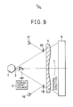
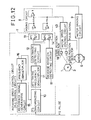
- the applicant of the present patent application proposed a construction for a laser printer as shown in Fig. 14 in Japanese Patent application No. 63-1517.
- This laser printer is provided with a polygonal rotating mirror 1 driven by a scanner motor for continuous rotation.
- a laser beam emitted from a signal light source 2 is reflected by the reflecting surfaces 3 each being a nonspherical surface of the polygonal rotating mirror 1, and then the reflected laser beam is focused on the circumference of a photoconductive drum 5.
- the scanner motor is controlled so as to operate continuously at a constant rotating speed on the basis of the result of comparison of a pulse signal generated by the scanner motor, for example, a FG pulse signal, and a reference clock generated by a quartz-crystal oscillator.
- a PLL control circuit compares the FG pulse signal with the reference clock, and then regulates a driving voltage applied to the scanner motor on the basis of the phase deviation and frequency deviation of the FG pulse signal from the reference clock so that the scanner motor operates at a constant rotating speed.
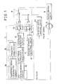
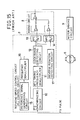
- a scanner motor controller for controlling the rotating speed of the scanner motor will be described with reference to Fig. 15.
- a scanner motor 6, a rotating speed control circuit 7, a mixing circuit 8 and a motor driving circuit 9 are connected in a loop.
- the rotating speed control circuit 7 comprises a FG synchronizing circuit 10 which receives the FG pulse signal from the scanner motor 6, an AFC timing frequency demultiplier 11 and a lock range detecting circuit 12 and a frequency DA converter 13, which are connected in series in that order, a phase DA converter 14 connected in parallel to the lock range detecting circuit 12 and connected to the mixing circuit 8, a frequency demultiplier 16 connected to the FG synchronizing circuit 10, a reference signal generating circuit 15 having a quartz-crystal oscillator and connected to the frequency demultiplier 16, and a reverse rotation detecting circuit 17 connected to the phase DA converter 14 and the lock range detecting circuit 12.
- a reflecting mirror 18 is disposed on the path of a laser beam reflected by each reflecting surface 3 of the polygonal rotating mirror 1 and falling on a scanning start position on the circumference of the photoconductive drum 5, and a start position detector 19 is disposed so as to receive a laser beam reflected by the reflecting mirror 18.
- the scanner motor 6 When driven for rotation by the motor driving circuit 9, the scanner motor 6 generates a FG pulse signal.
- the FG pulse signal is compared with a reference signal generated by the reference signal generating circuit 15 by the FG synchronizing circuit 10, and then the scanner motor 6 is controlled for operation at a constant rotating speed on the basis of the result of the comparison.
- a signal provided by the start position detector 19 is used for deciding the start position of the laser beam reflected by the polygonal rotating mirror 1, namely, a position of the laser beam failing on a scanning start position on the circumference of the photoconductive drum 5.
- the polygonal rotating mirror 1 can be rotated at a constant rotating speed by maintaining the scanner motor 6 at a constant rotating speed.
- the scanning speed of the scanning laser beam on the circumference of the photoconductive drum 5 must be constant, and the laser beam must be projected on the photoconductive drum 5 at regular time intervals by the six reflecting surfaces 3 of the polygonal rotating mirror 1 having the shape of a hexagonal prism. Therefore, the regular rotational movement of the polygonal rotating mirror 1 in each turn thereof is essential and the simple control of the rotating speed of the polygonal rotating mirror 1 is unable to make the laser printer function satisfactorily.
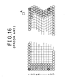
- the scanning speed varies periodically at a period corresponding to one turn of the polygonal rotating mirror 1 even if the polygonal rotating mirror 1 is rotated at a constant rotating speed, when the center hole of the polygonal rotating mirror 1 is eccentric with respect to the polygonal circumference thereof. Furthermore, the periodical variation of the scanning speed causes variation in scanning distance even if the scanning start position is constant. In such a case, the scanning end position varies periodically and, when the laser printer is operated to draw a straight line along the feed direction, a zigzag line as indicated at A in Fig. 16 is printed and hence the laser printer is unable to print in high print quality.
- transverse direction is the scanning direction and numerals indicated on the left side are the numbers of the sequential scanning lines.
- a motor driving circuit controlled by a rotating speed control circuit which compares a FG pulse signal generated by a scanner motor for rotating a polygonal rotating mirror to reflect a laser beam for scanning operation with a reference clock to determine the deviations of the phase and frequency of the FG pulse signal respectively from those of the reference clock and controls the output voltage of the motor driving circuit so that the scanner motor operates at a constant rotating speed, is connected to a rotating speed varying circuit for varying the rotating speed of the scanner motor within one turn of the output shaft of the scanner motor.
- the scanner motor is controlled for operation at a constant rotating speed by the rotating speed control circuit, and the rotating speed of the scanner motor is varied within one turn of the polygonal rotating mirror according to a rotating speed varying signal generated by the rotating speed varying circuit to correct variations in scanning distance and scanning speed attributable to mechanical errors in the polygonal rotating mirror so that the scanning beam is reflected at a constant period and at a constant scanning speed.
- a scanner motor controller for an optical scanning apparatus having a polygonal rotating mirror for reflecting a laser beam for scanning operation and a scanner motor for driving the polygonal rotating mirror for rotation, comprises a motor driving circuit for driving the scanner motor, a rotating speed control circuit which compares a FG pulse signal generated by the scanner motor with a reference clock and controls the motor driving circuit on the basis of the respective deviations of the phase and frequency of the FG pulse signal from the reference clock so that the scanner motor operates at a constant rotating speed, and a rotating speed varying circuit connected to the motor driving circuit to determine a time interval between a moment when a laser beam passes one end of a range swept by the laser beam and a moment when the laser beam passes the other end of the range on the basis of the output signals of detectors for detecting the laser beam, and to provide a rotating speed varying signal on the basis of the time interval.
- a rotating speed varying signal provided by the rotating speed varying circuit is superposed on a control signal provided by the rotating speed control circuit to control the motor driving circuit so that the scanner motor is driven for operation at a constant rotating speed, so that rotating speed of the scanner motor is varied within an angle of rotation for each reflecting surface of the polygonal rotating mirror to correct errors in the scanning operation of the laser beam reflected by each reflecting surface of the polygonal rotating mirror attributable to mechanical errors, such as the eccentric attachment of the polygonal rotating mirror on the output shaft of the scanner motor, in the polygonal rotating mirror, so that the laser beam is reflected to scan at a constant period and a constant scanning speed through a constant scanning distance and thereby print quality is improved.
- a scanner motor controller for an optical scanning apparatus having a polygonal rotating mirror for reflecting a laser beam for scanning operation and a scanner motor for driving the polygonal rotating mirror for rotation comprises: a motor driving circuit for driving the scanner motor; a rotating speed control circuit which compares a FG pulse signal generated by the scanner motor with a reference clock and controls the motor driving circuit on the basis of the phase deviation and frequency deviation of the FG pulse signal from the reference clock so that the scanner motor operates at a constant rotating speed; a start position detector disposed in a range swept by a laser beam to provide a start signal upon the detection of a laser beam; an end position detector disposed at a position in the range to provide an end signal upon the detection of a laser beam; and a motor speed control circuit connected to the motor driving circuit and comprising a block signal memory which counts the number of pulses of the reference clock generated in a period between the start signal and the end signal corresponding to an angle of rotation of the polygonal rotating mirror for each
- the rotating speed control circuit controls the scanner motor for operation at a constant rotating speed, while a rotating speed varying signal produced by the motor speed control circuit is superposed on a control signal provided by the rotating speed control circuit, so that the rotating speed of the scanner motor is varied within each turn of the polygonal rotating mirror to correct errors in the scanning period, scanning speed and scanning distance of the laser beam reflected by the polygonal rotating mirror attributable to mechanical errors in the polygonal rotating mirror.
- the laser beam reflected by the polygonal rotating mirror scans the circumference of a photoconductive drum at a constant period and at a constant scanning speed through a constant scanning distance to print in high print quality.
- An optical scanning system associated with a scanner motor controller in a first embodiment according to the present invention is similar in construction to that described previously with reference to Fig. 14, and hence the description thereof will be omitted.
- the scanner motor controller comprises a rotating speed control circuit 7, a mixing circuit 8, a motor driving circuit 9, and a rotating speed varying circuit 20.
- a scanner motor 6 is included in the loop of the rotating speed control circuit 7, the mixing circuit 8 and the motor driving circuit 9.
- the rotating speed control circuit 7 comprises a FG synchronizing circuit 10 which receives a FG pulse signal from the scanner motor 6, an AFC timing frequency demultiplier 11 and a lock range detecting circuit 12, which are connected in series in that order, a frequency DA converter 13 and a phase DA converter 14, which are connected in parallel, connected to the mixing circuit 8, a frequency demultiplier 16 connected to the FG synchronizing circuit 10, a reference clock generating circuit 15 connected to the frequency demultiplier 16, and a reverse rotation detecting circuit 17 connected to the lock range detecting circuit 12 and the phase DA converter 14.
- a rotating speed varying circuit 20 is connected to the scanner motor 6 and the mixing circuit 8.
- the rotating speed varying circuit 20 consists of two monostable multivibrators 23 and 24, variable resistors 21 (VR1) and 22 (VR2) connected respectively to the monostable multivibrators 23 and 24, and a variable resistor 25 (VR3) connected to the monostable multivibrator 22.
- the scanner motor 6 When driven by the motor driving circuit 9, the scanner motor 6 generates a FG pulse signal.
- the FG synchronizing circuit 10 compares the FG pulse signal with a reference clock generated by the reference clock generating circuit 15.
- the scanner motor 6 is controlled for operation at a constant rotating speed on the basis of the result of the comparison.
- the polygonal rotating mirror 1 is rotated by the scanner motor 6 thus controlled to reflect a scanning beam, and the condition of the scanning beam is detected.
- the scanning beam is not necessarily reflected in a constant condition even if the polygonal mirror 1 is rotated uniformly at a constant rotating speed.
- the variable resistors 21 and 22 are adjusted to make the rotating speed varying circuit 18 generate a rotating speed varying signal to vary the rotating speed of the scanner motor 6 within one turn of the polygonal rotating mirror 1 so that variations in the scanning beam attributable to mechanical errors in the polygonal rotating mirror 1 are cancelled.
- the scanner motor 6 is provided with a signal generator, not shown, using a Hall element or the like to generate a pulse every turn of the output shaft thereof.
- the monostable multivibrator 23 is actuated at the leading edge or trailing edge of the pulse generated by the signal generator of the scanner motor 6 to generate a pulse having a pulse width of t1
- the monostable multivibrator 24 is actuated by the pulse generated by the monostable multivibrator 23 to generate a pulse having a pulse width of t2
- the variable resistor 22 is adjusted so that t2/T (T is the period of the pulse signal generated by the monostable multivibrator 24) is approximately 1/2.
- the output level of the rotating speed varying circuit 20 is adjusted by the variable resistor 25.
- a rotating speed varying signal produced by the rotating speed varying circuit 20 is superposed on a rotating speed control signal produced by the rotating speed control circuit 7 to vary the rotating speed of the scanner motor 6 within every turn of the polygonal rotating mirror 1. Since t2/T is approximately 1/2, the duty factor of the output signal of the rotating speed varying circuit 20 is 50%, so that rotating speed of the polygonal rotating mirror 1 is controlled smoothly by acceleration during half a turn and deceleration during a half a turn.
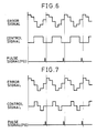
- Fig. 6 shows an error signal and a corresponding rotating speed varying signal generated when the rotating speed of the polygonal rotating mirror varies periodically. Thus, errors in the scanning speed of the scanning beam are cancelled.
- a scanner motor controller in a second embodiment according to the present invention is substantially the same in construction as the scanner motor controller in the first embodiment, except that the scanner motor controller in the second embodiment is provided additionally with monostable multivibrators 28 and 29 provided respectively with variable resistors 26 (VR4) and 27 (VR5) and connected to the output of the monostable multivibrator 22.
- the rotating speed varying circuit 20 of the scanner controller in the second embodiment provides an acceleration and deceleration pulse signal.
- the pulse width t4 is adjusted by the variable resistor 26, and the pulse width t5 is adjusted by the variable resistor 27.
- the waveform of the output signal of the rotating speed varying circuit 20 is the same as the error signal in pulse width and amplitude.
- the rotating speed of the polygonal mirror 1 is regulated subtly within every turn of the polygonal rotating mirror 1.
- a scanner motor controller in a third embodiment according to the present invention is substantially the same in construction as those of the foregoing embodiments and hence parts like or corresponding to those previously described with reference to Figs. 1, 2 and 4 are denoted by the same reference characters and the description thereof will be omitted.
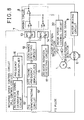
- An optical system associated with the scanner motor controller in the third embodiment is provided, in addition to the components of the optical system shown in Fig. 14, with a reflecting mirror 30, which is disposed at the scanning end position of the scanning beam.
- the scanner motor controller comprises, in addition to the components of the scanner motor controller shown in Fig. 15, an end position detector 31 disposed so as to receive the scanning beam reflected by the reflecting mirror 30, and a motor speed control circuit 32 connected to the pulse signal generating circuit, not shown, of the scanner motor 6, the start position detector 19, the end position detector 31 and the mixing circuit 8.
- the motor speed control circuit 32 comprises an exclusive OR circuit 33 having input terminals connected respectively to the start position detector 19 and the end position detector 31; a first counter 34 having an input terminal connected to the output terminal of the exclusive OR circuit 33; an AND gate 35 having input terminals connected respectively to the 22 terminal and the 23 terminal of the first counter 34, and an output terminal connected to the CLEAR terminal of the first counter 34; an AND gate 36 having input terminals connected respectively to the 20 terminal of the first counter 34 and the reference clock generating circuit 15; a second counter 37 having an input terminal connected to the output terminal of the AND gate 36; a memory 38 having an input terminal connected to the output terminal of the second counter 37, a DA converter 39 having an input terminal connected to the memory 38; a monostable multivibrator 41 connected to a variable resistor 40 (VR6) and having an input terminal connected to the output terminal of the DA converter 39; and a variable resistor 42 (VR7) connected to the output terminal of the monostable multivibrator 41.
- VR6 variable resistor 40
- the first counter 34 is cleared when the count reaches twelve, provided that the polygonal rotating mirror 1 is a hexagonal rotating mirror, because the first counter counts two pulses, i.e., a start pulse and an end pulse, for each reflecting surface of the polygonal rotating mirror 1.
- the scanner motor 6 When driven by the motor driving circuit 9, the scanner motor 6 generates a FG pulse signal.
- the FG synchronizing circuit 10 compares the FG pulse signal with a reference clock generated by the reference clock generating circuit 15, and the scanner motor controller controls the scanner motor 6 on the basis of the comparison so that the scanner motor 6 operates at a constant rotating speed.
- the scanning condition of the scanning beam is not necessarily constant even if the polygonal rotating mirror 1 is rotated uniformly at a constant rotating speed, because mechanical errors in the polygonal rotating mirror 1 affects the reflecting mode of the polygonal rotating mirror 1.
- the start position detector 19 and the end position detector 31 give detection signals to the exclusive OR circuit 33.
- the exclusive OR circuit 33 gives an output signal to the first counter 34.
- the first counter 34 is cleared at the sixth end pulse (twelfth output signal of the first counter 34).
- An output signal which appears at the 20 terminal of the first counter 34 corresponds to a time interval between a moment when the scanning beam is detected by the start position detector 19 and a moment when the scanning beam is detected by the end position detector 31.
- the logical product of the output signal and the reference clock namely, a time interval signal for the corresponding reflecting surface 3 of the polygonal rotating mirror 1 is applied to the second counter 37 and then the time interval signal is stored in the memory 38.
- the DA converter 39 produces a stepped disturbance signal corresponding to frequency through the F/V conversion of the time interval signals.
- the disturbance signal is applied to the motor driving circuit 9 as a value corresponding to the scanning speed in the precedent scanning cycle.
- the disturbance signal is applied to the motor driving circuit 9 at an appropriate phase according to the frequency characteristics of the scanner motor 6 so that errors in the scanning speed for each reflecting surface 3 are cancelled.
- Fig. 11 shows an example of such a control mode, in which a control signal cancelling the error signal is applied to the motor driving circuit 9.
- the disturbance signal corresponding to the irregularity in the scanning speed in the preceding turn of the polygonal rotating mirror 1 to a control signal provided by the rotating speed control circuit 7 (PLL control circuit) to diminish irregularity in the scanning speed. Consequently, all the scanning beams reflected by the reflecting surfaces 3 of the polygonal rotating mirror 1 fall on the circumference of the photoconductive drum 5 substantially at the same scanning end position though dots may be dislocated locally from the correct position within the scanning range.
- a scanner motor controller in a fourth embodiment according to the present invention will be described hereinafter with reference to Fig. 12 and 13, in which parts like or corresponding to those previously described in conjunction with the foregoing embodiments are denoted by the same reference characters and the description thereof will be omitted.
- An optical system associated with the scanner motor controller in the fourth embodiment is provided, in addition to the components shown in Fig. 14, a reflecting mirror 30 at the scanning end position of the scanning beam.
- the scanner motor controller comprises, in addition to the components shown in Fig. 15, a scanning end position detector 31 which receives the scanning beam reflected by the reflecting mirror 30 to detect the arrival of the scanning beam at the scanning end position, and a motor speed control circuit 43 having input terminals connected to the start position detector 19, the end position detector 31 and the scanner motor 6, and an output terminal connected to the mixing circuit 8, which in turn is connected to the motor driving circuit 9.
- the motor speed control circuit 43 comprisiveses: a flip-flop 44, a block pulse generating circuit 45, a jitter measuring circuit 46, a latch circuit 47, an averaging circuit, a block signal memory, a DA converter 50, a low-pass filter 51, a jitter correction circuit 52 and an amplitude adjustment circuit, which are connected in series in that order.
- the amplitude adjustment circuit 53 is connected to the mixing circuit 8.
- a reference clock generating circuit 54 which generates a reference clock is connected to the jitter measurement circuit 46.
- Preset circuits 55 and 56 set for the scanning speed data stored in the block signal memory 49 are connected respectively to block data comparators 57 and 58.
- the block data comparators 57 and 58 are connected to the latch circuit 47 and respectively to a maximum value circuit 59 and a minimum value circuit 60.
- the maximum value circuit 59 and the minimum value circuit 60 are connected to a subtraction circuit 62, which in turn is connected to a data memory 61 and a comparator 63.
- the comparator 63 is connected through an analog switch 64 to the block signal memory 49, the DA converter 50 and the amplitude adjustment circuit 53.
- the scanning condition of the scanning beam is not necessarily constant even if the polygonal rotating mirror 1 is rotated uniformly at a constant rotating speed, because the scanning condition of the scanning beam is affected by mechanical errors in the polygonal rotating mirror 1.
- the arrival of the scanning beam at the scanning start position and at the scanning end position is detected by the start position detector 19 and the end position detector 31.
- the block pulse generating circuit 45 generates a block pulse signal in response to detection signals provided by the start position detector 19 and the end position detector 31. A time interval in which the block pulse signal is HIGH is measured in a digital mode by using the reference clock.
- the averaging circuit 48 averages errors in scanning speed for the reflecting surfaces 3 to obtain a mean error and stores the mean error in the block signal memory 49 before the motor speed control circuit 43 functions.
- the scanning speed data is converted into a corresponding analog signal by the DA converter 50, the analog signal is filtered by the low-pass filter 51 to obtain a jitter correction signal by the jitter correction circuit 52. Then, the jitter correction signal is applied through the amplitude adjustment circuit 53 to the mixing circuit 8 to control the rotating speed of the scanner motor.
- the scanning speed of the scanning beam reflected by each reflecting surface 3 of the polygonal rotating mirror 1 provided by the latch circuit 47 is compared with the preset scanning speed of the laser beam reflected by the same reflecting surface 3 in the preceding scanning cycle, the difference between the maximum and the minimum within the block is determined by the subtraction circuit 62, the difference is compared with the data of the preceding sector by the comparator 63, and then the rotating speed of the scanner motor 6 is controlled so that the phase and amplitude are corrected to optimum values. That is, the phase and the amplitude are adjusted in a digital mode so that the absolute value of the difference between the maximum and the minimum within the block is reduced to a minimum.
- Initial data stored in the preset circuits 55 and 56 or in the block signal memory 49 may be a scanning speed data stored in a ROM or the like in assembling the scanner motor controller as a fixed constant.
- the scanning speed is subject to variation due to the aging of the optical system and variation in the ambient condition, it is desirable to renew the initial data in setting the printer or before starting the printing operation.
- renewing the initial data data must be processed only by the rotating speed control circuit 7 while the motor speed control circuit 43 is disconnected from the mixing circuit 8.
Landscapes
- Physics & Mathematics (AREA)
- Engineering & Computer Science (AREA)
- General Physics & Mathematics (AREA)
- Optics & Photonics (AREA)
- General Engineering & Computer Science (AREA)
- Theoretical Computer Science (AREA)
- Multimedia (AREA)
- Signal Processing (AREA)
- Power Engineering (AREA)
- Facsimile Scanning Arrangements (AREA)
- Mechanical Optical Scanning Systems (AREA)
- Laser Beam Printer (AREA)
Applications Claiming Priority (6)
| Application Number | Priority Date | Filing Date | Title |
|---|---|---|---|
| JP129999/88 | 1988-05-27 | ||
| JP63129999A JPH01303085A (ja) | 1988-05-27 | 1988-05-27 | スキヤナモータ回転制御回路 |
| JP63167099A JPH0216523A (ja) | 1988-07-05 | 1988-07-05 | 光走査装置 |
| JP167099/88 | 1988-07-05 | ||
| JP169864/88 | 1988-07-07 | ||
| JP63169864A JPH0219820A (ja) | 1988-07-07 | 1988-07-07 | スキヤナモータ回転制御回路 |
Publications (3)
| Publication Number | Publication Date |
|---|---|
| EP0343995A2 true EP0343995A2 (fr) | 1989-11-29 |
| EP0343995A3 EP0343995A3 (fr) | 1992-01-08 |
| EP0343995B1 EP0343995B1 (fr) | 1994-07-20 |
Family
ID=27316043
Family Applications (1)
| Application Number | Title | Priority Date | Filing Date |
|---|---|---|---|
| EP89305322A Expired - Lifetime EP0343995B1 (fr) | 1988-05-27 | 1989-05-25 | Appareil de commande d'un moteur de balayage pour commander la vitesse de rotation d'un moteur de balayage |
Country Status (4)
| Country | Link |
|---|---|
| US (1) | US4975626A (fr) |
| EP (1) | EP0343995B1 (fr) |
| KR (1) | KR930003035B1 (fr) |
| DE (1) | DE68916862T2 (fr) |
Cited By (1)
| Publication number | Priority date | Publication date | Assignee | Title |
|---|---|---|---|---|
| EP1096292A2 (fr) * | 1999-10-28 | 2001-05-02 | Canon Kabushiki Kaisha | Dispositif de balayage optique et appareil de formation d'images en couleurs |
Families Citing this family (29)
| Publication number | Priority date | Publication date | Assignee | Title |
|---|---|---|---|---|
| GB2217051B (en) * | 1988-04-07 | 1992-12-09 | Sony Corp | A servo system for a motor |
| US5450121A (en) * | 1991-12-20 | 1995-09-12 | Compaq Computer Corporation | Margin control for laser printers |
| JP2757494B2 (ja) * | 1989-09-29 | 1998-05-25 | ブラザー工業株式会社 | 走査露光装置 |
| EP0450529B1 (fr) * | 1990-03-31 | 1997-01-29 | Sanyo Electric Co., Ltd. | Circuit d'asservissement de moteur pour appareil de reproduction de disque |
| US5083140A (en) * | 1990-04-10 | 1992-01-21 | Minnesota Mining And Manufacturing Company | Multiple charge images initiation with scan synchronization |
| JP2779053B2 (ja) * | 1990-09-25 | 1998-07-23 | 株式会社日立製作所 | 光走査装置 |
| US5153644A (en) * | 1991-08-19 | 1992-10-06 | Xerox Corporation | Dual mode correction of image distortion in a xerographic printing apparatus |
| US5225923A (en) * | 1992-07-09 | 1993-07-06 | General Scanning, Inc. | Scanning microscope employing improved scanning mechanism |
| JP3212200B2 (ja) * | 1992-11-27 | 2001-09-25 | 東芝テック株式会社 | 光走査装置 |
| US5445017A (en) * | 1993-08-24 | 1995-08-29 | Mita Industrial Co., Ltd. | Motor start examining device and method |
| US5530642A (en) * | 1994-11-14 | 1996-06-25 | Xerox Corporation | Control system for aspect ratio and magnification of a raster output scanner |
| US5943087A (en) * | 1995-09-13 | 1999-08-24 | Rohm Co., Ltd. | Laser beam printing machine |
| US5808658A (en) * | 1997-03-31 | 1998-09-15 | Xerox Corporation | Regulator with phase shift for polygon rephase without divide |
| US6252618B1 (en) | 2000-06-15 | 2001-06-26 | Lexmark International, Inc. | Method of controlling print registration in an electrophotographic machine |
| US6285383B1 (en) | 2000-09-14 | 2001-09-04 | Lexmark International, Inc. | Method of controlling laser scanner phase in a multicolor electrophotographic machine |
| US6459443B1 (en) | 2001-06-21 | 2002-10-01 | Lexmark International, Inc | Method of minimizing print delay due to mirror motor warm-up in an electrophotographic machine |
| US6831736B2 (en) * | 2002-10-07 | 2004-12-14 | Applied Materials Israel, Ltd. | Method of and apparatus for line alignment to compensate for static and dynamic inaccuracies in scanning |
| JP4695342B2 (ja) * | 2003-09-03 | 2011-06-08 | 富士通株式会社 | 光スイッチ制御装置および移動体制御装置 |
| US7206012B2 (en) * | 2004-03-24 | 2007-04-17 | Lexmark International, Inc. | Memory device on optical scanner and apparatus and method for storing characterizing information on the memory device |
| US7349123B2 (en) * | 2004-03-24 | 2008-03-25 | Lexmark International, Inc. | Algorithms and methods for determining laser beam process direction position errors from data stored on a printhead |
| US7375738B2 (en) * | 2004-03-24 | 2008-05-20 | Lexmark International, Inc. | Electronic systems and methods for reducing laser beam process direction position errors |
| US7639407B2 (en) * | 2004-03-24 | 2009-12-29 | Lexmark International, Inc. | Systems for performing laser beam linearity correction and algorithms and methods for generating linearity correction tables from data stored in an optical scanner |
| US7837302B2 (en) * | 2005-11-03 | 2010-11-23 | Marvell International Technology Ltd. | Inkjet printhead system and method using laser-based heating |
| JP5000325B2 (ja) * | 2007-02-09 | 2012-08-15 | 東芝機械株式会社 | 位相差検出装置及び回転位置検出装置 |
| JP2008241345A (ja) | 2007-03-26 | 2008-10-09 | Toshiba Mach Co Ltd | 位相検出装置及び位置検出装置 |
| WO2009128198A1 (fr) * | 2008-04-15 | 2009-10-22 | パナソニック株式会社 | Dispositif d'entraînement de moteur, dispositif à circuit intégré, dispositif à moteur et système d'entraînement de moteur |
| JP2009294542A (ja) * | 2008-06-06 | 2009-12-17 | Canon Inc | 光走査装置及び画像形成装置 |
| JP5906115B2 (ja) * | 2012-03-29 | 2016-04-20 | 川崎重工業株式会社 | 光走査装置及びレーザ加工装置 |
| CN112742801A (zh) * | 2020-12-30 | 2021-05-04 | 镇江长悦光电科技有限公司 | 一种高速激光清洗装置及其使用方法 |
Citations (5)
| Publication number | Priority date | Publication date | Assignee | Title |
|---|---|---|---|---|
| US4310757A (en) * | 1978-07-07 | 1982-01-12 | Pitney Bowes Inc. | Apparatus for correcting scanning speed in a polygon used for laser scanning |
| US4410234A (en) * | 1979-04-10 | 1983-10-18 | Fumitsu Limited | Timing pulse generator for scanning apparatus |
| US4587531A (en) * | 1984-11-05 | 1986-05-06 | Eastman Kodak Company | Clock signal producing apparatus |
| US4694156A (en) * | 1986-02-14 | 1987-09-15 | Xerox Corporation | Pixel placement sensing arrangement using split detecting elements |
| US4734715A (en) * | 1985-05-31 | 1988-03-29 | Kabushiki Kaisha Toshiba | Variable light beam scanning apparatus |
Family Cites Families (1)
| Publication number | Priority date | Publication date | Assignee | Title |
|---|---|---|---|---|
| JPS6189765A (ja) * | 1984-10-08 | 1986-05-07 | Fuji Photo Film Co Ltd | 記録走査装置 |
-
1989
- 1989-05-25 DE DE68916862T patent/DE68916862T2/de not_active Expired - Fee Related
- 1989-05-25 EP EP89305322A patent/EP0343995B1/fr not_active Expired - Lifetime
- 1989-05-26 KR KR1019890007093A patent/KR930003035B1/ko not_active IP Right Cessation
- 1989-05-26 US US07/357,604 patent/US4975626A/en not_active Expired - Fee Related
Patent Citations (5)
| Publication number | Priority date | Publication date | Assignee | Title |
|---|---|---|---|---|
| US4310757A (en) * | 1978-07-07 | 1982-01-12 | Pitney Bowes Inc. | Apparatus for correcting scanning speed in a polygon used for laser scanning |
| US4410234A (en) * | 1979-04-10 | 1983-10-18 | Fumitsu Limited | Timing pulse generator for scanning apparatus |
| US4587531A (en) * | 1984-11-05 | 1986-05-06 | Eastman Kodak Company | Clock signal producing apparatus |
| US4734715A (en) * | 1985-05-31 | 1988-03-29 | Kabushiki Kaisha Toshiba | Variable light beam scanning apparatus |
| US4694156A (en) * | 1986-02-14 | 1987-09-15 | Xerox Corporation | Pixel placement sensing arrangement using split detecting elements |
Cited By (4)
| Publication number | Priority date | Publication date | Assignee | Title |
|---|---|---|---|---|
| EP1096292A2 (fr) * | 1999-10-28 | 2001-05-02 | Canon Kabushiki Kaisha | Dispositif de balayage optique et appareil de formation d'images en couleurs |
| EP1096292A3 (fr) * | 1999-10-28 | 2002-07-10 | Canon Kabushiki Kaisha | Dispositif de balayage optique et appareil de formation d'images en couleurs utilisant ledit dispositif |
| US7015940B1 (en) | 1999-10-28 | 2006-03-21 | Canon Kabushiki Kaisha | Scanning optical apparatus and color image forming apparatus using the same |
| US7365764B2 (en) | 1999-10-28 | 2008-04-29 | Canon Kabushiki Kaisha | Scanning optical apparatus and color image forming apparatus using the same |
Also Published As
| Publication number | Publication date |
|---|---|
| DE68916862T2 (de) | 1995-03-02 |
| EP0343995B1 (fr) | 1994-07-20 |
| DE68916862D1 (de) | 1994-08-25 |
| KR930003035B1 (ko) | 1993-04-16 |
| KR900019328A (ko) | 1990-12-24 |
| US4975626A (en) | 1990-12-04 |
| EP0343995A3 (fr) | 1992-01-08 |
Similar Documents
| Publication | Publication Date | Title |
|---|---|---|
| EP0343995B1 (fr) | Appareil de commande d'un moteur de balayage pour commander la vitesse de rotation d'un moteur de balayage | |
| EP1392049B1 (fr) | Appareil de formation d'image | |
| US5671076A (en) | Image display device using vibrating mirror | |
| US4962981A (en) | Optical scanner | |
| US5444525A (en) | Image forming apparatus with image recording timing control | |
| US5966231A (en) | Method and apparatus for aligning multiple laser beams | |
| US5541637A (en) | Image exposure apparatus with compensation for variations in scanning rate | |
| US4630223A (en) | Scanner amplitude stabilization system | |
| US5982402A (en) | Apparatus for printing color image by combination of optical beam scanning units and photosensitive drums | |
| US4800271A (en) | Galvanometric optical scanning system having synchronization photodetectors | |
| US6133932A (en) | Method and apparatus for adjusting a line synchronization signal in response to photoreceptor motion | |
| US20020012549A1 (en) | Image forming apparatus with controlled image carrier rotation driving based on previous rotation state | |
| EP0691783A2 (fr) | Générateur d'horloge d'éléments d'image | |
| US20100067927A1 (en) | Optical scanner and image forming apparatus including same | |
| US5059987A (en) | Synchronizing signal generating system | |
| US5193013A (en) | Scanner with non-linearity compensating pixel clock | |
| US6639620B2 (en) | Light beam scanning apparatus | |
| US5122678A (en) | Image clock signal generating system with initial phase matching means in phase-locked loop | |
| US5095315A (en) | Multipoint synchronization optical writing apparatus | |
| US20030214572A1 (en) | Image forming apparatus | |
| JPH0219820A (ja) | スキヤナモータ回転制御回路 | |
| JP3382385B2 (ja) | 画像形成装置 | |
| KR100340158B1 (ko) | 화상 형성 장치 및 방법 | |
| US5793036A (en) | Synchronizing signal generating circuit for optical scanning device | |
| US5161046A (en) | Beam position control apparatus |
Legal Events
| Date | Code | Title | Description |
|---|---|---|---|
| PUAI | Public reference made under article 153(3) epc to a published international application that has entered the european phase |
Free format text: ORIGINAL CODE: 0009012 |
|
| 17P | Request for examination filed |
Effective date: 19890602 |
|
| AK | Designated contracting states |
Kind code of ref document: A2 Designated state(s): DE FR GB |
|
| PUAL | Search report despatched |
Free format text: ORIGINAL CODE: 0009013 |
|
| AK | Designated contracting states |
Kind code of ref document: A3 Designated state(s): DE FR GB |
|
| 17Q | First examination report despatched |
Effective date: 19921209 |
|
| GRAA | (expected) grant |
Free format text: ORIGINAL CODE: 0009210 |
|
| AK | Designated contracting states |
Kind code of ref document: B1 Designated state(s): DE FR GB |
|
| REF | Corresponds to: |
Ref document number: 68916862 Country of ref document: DE Date of ref document: 19940825 |
|
| ET | Fr: translation filed | ||
| PLBE | No opposition filed within time limit |
Free format text: ORIGINAL CODE: 0009261 |
|
| STAA | Information on the status of an ep patent application or granted ep patent |
Free format text: STATUS: NO OPPOSITION FILED WITHIN TIME LIMIT |
|
| 26N | No opposition filed | ||
| PGFP | Annual fee paid to national office [announced via postgrant information from national office to epo] |
Ref country code: FR Payment date: 20010518 Year of fee payment: 13 |
|
| PGFP | Annual fee paid to national office [announced via postgrant information from national office to epo] |
Ref country code: DE Payment date: 20010522 Year of fee payment: 13 |
|
| PGFP | Annual fee paid to national office [announced via postgrant information from national office to epo] |
Ref country code: GB Payment date: 20010523 Year of fee payment: 13 |
|
| REG | Reference to a national code |
Ref country code: GB Ref legal event code: IF02 |
|
| PG25 | Lapsed in a contracting state [announced via postgrant information from national office to epo] |
Ref country code: GB Free format text: LAPSE BECAUSE OF NON-PAYMENT OF DUE FEES Effective date: 20020525 |
|
| PG25 | Lapsed in a contracting state [announced via postgrant information from national office to epo] |
Ref country code: DE Free format text: LAPSE BECAUSE OF NON-PAYMENT OF DUE FEES Effective date: 20021203 |
|
| GBPC | Gb: european patent ceased through non-payment of renewal fee |
Effective date: 20020525 |
|
| PG25 | Lapsed in a contracting state [announced via postgrant information from national office to epo] |
Ref country code: FR Free format text: LAPSE BECAUSE OF NON-PAYMENT OF DUE FEES Effective date: 20030131 |
|
| REG | Reference to a national code |
Ref country code: FR Ref legal event code: ST |