EP0343976A2 - Filterapparat - Google Patents
Filterapparat Download PDFInfo
- Publication number
- EP0343976A2 EP0343976A2 EP89305283A EP89305283A EP0343976A2 EP 0343976 A2 EP0343976 A2 EP 0343976A2 EP 89305283 A EP89305283 A EP 89305283A EP 89305283 A EP89305283 A EP 89305283A EP 0343976 A2 EP0343976 A2 EP 0343976A2
- Authority
- EP
- European Patent Office
- Prior art keywords
- housing
- filter element
- end cap
- ribs
- seal edge
- Prior art date
- Legal status (The legal status is an assumption and is not a legal conclusion. Google has not performed a legal analysis and makes no representation as to the accuracy of the status listed.)
- Granted
Links
Images

Classifications
-
- B—PERFORMING OPERATIONS; TRANSPORTING
- B29—WORKING OF PLASTICS; WORKING OF SUBSTANCES IN A PLASTIC STATE IN GENERAL
- B29C—SHAPING OR JOINING OF PLASTICS; SHAPING OF MATERIAL IN A PLASTIC STATE, NOT OTHERWISE PROVIDED FOR; AFTER-TREATMENT OF THE SHAPED PRODUCTS, e.g. REPAIRING
- B29C66/00—General aspects of processes or apparatus for joining preformed parts
- B29C66/50—General aspects of joining tubular articles; General aspects of joining long products, i.e. bars or profiled elements; General aspects of joining single elements to tubular articles, hollow articles or bars; General aspects of joining several hollow-preforms to form hollow or tubular articles
- B29C66/51—Joining tubular articles, profiled elements or bars; Joining single elements to tubular articles, hollow articles or bars; Joining several hollow-preforms to form hollow or tubular articles
- B29C66/54—Joining several hollow-preforms, e.g. half-shells, to form hollow articles, e.g. for making balls, containers; Joining several hollow-preforms, e.g. half-cylinders, to form tubular articles
-
- B—PERFORMING OPERATIONS; TRANSPORTING
- B01—PHYSICAL OR CHEMICAL PROCESSES OR APPARATUS IN GENERAL
- B01D—SEPARATION
- B01D27/00—Cartridge filters of the throw-away type
- B01D27/005—Making filter elements not provided for elsewhere
-
- B—PERFORMING OPERATIONS; TRANSPORTING
- B01—PHYSICAL OR CHEMICAL PROCESSES OR APPARATUS IN GENERAL
- B01D—SEPARATION
- B01D27/00—Cartridge filters of the throw-away type
- B01D27/08—Construction of the casing
-
- B—PERFORMING OPERATIONS; TRANSPORTING
- B01—PHYSICAL OR CHEMICAL PROCESSES OR APPARATUS IN GENERAL
- B01D—SEPARATION
- B01D29/00—Filters with filtering elements stationary during filtration, e.g. pressure or suction filters, not covered by groups B01D24/00 - B01D27/00; Filtering elements therefor
- B01D29/11—Filters with filtering elements stationary during filtration, e.g. pressure or suction filters, not covered by groups B01D24/00 - B01D27/00; Filtering elements therefor with bag, cage, hose, tube, sleeve or like filtering elements
- B01D29/13—Supported filter elements
- B01D29/15—Supported filter elements arranged for inward flow filtration
-
- B—PERFORMING OPERATIONS; TRANSPORTING
- B01—PHYSICAL OR CHEMICAL PROCESSES OR APPARATUS IN GENERAL
- B01D—SEPARATION
- B01D35/00—Filtering devices having features not specifically covered by groups B01D24/00 - B01D33/00, or for applications not specifically covered by groups B01D24/00 - B01D33/00; Auxiliary devices for filtration; Filter housing constructions
- B01D35/02—Filters adapted for location in special places, e.g. pipe-lines, pumps, stop-cocks
-
- B—PERFORMING OPERATIONS; TRANSPORTING
- B29—WORKING OF PLASTICS; WORKING OF SUBSTANCES IN A PLASTIC STATE IN GENERAL
- B29C—SHAPING OR JOINING OF PLASTICS; SHAPING OF MATERIAL IN A PLASTIC STATE, NOT OTHERWISE PROVIDED FOR; AFTER-TREATMENT OF THE SHAPED PRODUCTS, e.g. REPAIRING
- B29C65/00—Joining or sealing of preformed parts, e.g. welding of plastics materials; Apparatus therefor
- B29C65/02—Joining or sealing of preformed parts, e.g. welding of plastics materials; Apparatus therefor by heating, with or without pressure
-
- B—PERFORMING OPERATIONS; TRANSPORTING
- B29—WORKING OF PLASTICS; WORKING OF SUBSTANCES IN A PLASTIC STATE IN GENERAL
- B29C—SHAPING OR JOINING OF PLASTICS; SHAPING OF MATERIAL IN A PLASTIC STATE, NOT OTHERWISE PROVIDED FOR; AFTER-TREATMENT OF THE SHAPED PRODUCTS, e.g. REPAIRING
- B29C66/00—General aspects of processes or apparatus for joining preformed parts
- B29C66/01—General aspects dealing with the joint area or with the area to be joined
- B29C66/05—Particular design of joint configurations
- B29C66/10—Particular design of joint configurations particular design of the joint cross-sections
- B29C66/13—Single flanged joints; Fin-type joints; Single hem joints; Edge joints; Interpenetrating fingered joints; Other specific particular designs of joint cross-sections not provided for in groups B29C66/11 - B29C66/12
- B29C66/131—Single flanged joints, i.e. one of the parts to be joined being rigid and flanged in the joint area
- B29C66/1312—Single flange to flange joints, the parts to be joined being rigid
-
- B—PERFORMING OPERATIONS; TRANSPORTING
- B29—WORKING OF PLASTICS; WORKING OF SUBSTANCES IN A PLASTIC STATE IN GENERAL
- B29C—SHAPING OR JOINING OF PLASTICS; SHAPING OF MATERIAL IN A PLASTIC STATE, NOT OTHERWISE PROVIDED FOR; AFTER-TREATMENT OF THE SHAPED PRODUCTS, e.g. REPAIRING
- B29C66/00—General aspects of processes or apparatus for joining preformed parts
- B29C66/50—General aspects of joining tubular articles; General aspects of joining long products, i.e. bars or profiled elements; General aspects of joining single elements to tubular articles, hollow articles or bars; General aspects of joining several hollow-preforms to form hollow or tubular articles
- B29C66/51—Joining tubular articles, profiled elements or bars; Joining single elements to tubular articles, hollow articles or bars; Joining several hollow-preforms to form hollow or tubular articles
- B29C66/54—Joining several hollow-preforms, e.g. half-shells, to form hollow articles, e.g. for making balls, containers; Joining several hollow-preforms, e.g. half-cylinders, to form tubular articles
- B29C66/543—Joining several hollow-preforms, e.g. half-shells, to form hollow articles, e.g. for making balls, containers; Joining several hollow-preforms, e.g. half-cylinders, to form tubular articles joining more than two hollow-preforms to form said hollow articles
-
- B—PERFORMING OPERATIONS; TRANSPORTING
- B29—WORKING OF PLASTICS; WORKING OF SUBSTANCES IN A PLASTIC STATE IN GENERAL
- B29C—SHAPING OR JOINING OF PLASTICS; SHAPING OF MATERIAL IN A PLASTIC STATE, NOT OTHERWISE PROVIDED FOR; AFTER-TREATMENT OF THE SHAPED PRODUCTS, e.g. REPAIRING
- B29C66/00—General aspects of processes or apparatus for joining preformed parts
- B29C66/50—General aspects of joining tubular articles; General aspects of joining long products, i.e. bars or profiled elements; General aspects of joining single elements to tubular articles, hollow articles or bars; General aspects of joining several hollow-preforms to form hollow or tubular articles
- B29C66/51—Joining tubular articles, profiled elements or bars; Joining single elements to tubular articles, hollow articles or bars; Joining several hollow-preforms to form hollow or tubular articles
- B29C66/54—Joining several hollow-preforms, e.g. half-shells, to form hollow articles, e.g. for making balls, containers; Joining several hollow-preforms, e.g. half-cylinders, to form tubular articles
- B29C66/545—Joining several hollow-preforms, e.g. half-shells, to form hollow articles, e.g. for making balls, containers; Joining several hollow-preforms, e.g. half-cylinders, to form tubular articles one hollow-preform being placed inside the other
-
- B—PERFORMING OPERATIONS; TRANSPORTING
- B01—PHYSICAL OR CHEMICAL PROCESSES OR APPARATUS IN GENERAL
- B01D—SEPARATION
- B01D2101/00—Types of filters having loose filtering material
- B01D2101/005—Types of filters having loose filtering material with a binder between the individual particles or fibres
-
- B—PERFORMING OPERATIONS; TRANSPORTING
- B29—WORKING OF PLASTICS; WORKING OF SUBSTANCES IN A PLASTIC STATE IN GENERAL
- B29C—SHAPING OR JOINING OF PLASTICS; SHAPING OF MATERIAL IN A PLASTIC STATE, NOT OTHERWISE PROVIDED FOR; AFTER-TREATMENT OF THE SHAPED PRODUCTS, e.g. REPAIRING
- B29C65/00—Joining or sealing of preformed parts, e.g. welding of plastics materials; Apparatus therefor
- B29C65/02—Joining or sealing of preformed parts, e.g. welding of plastics materials; Apparatus therefor by heating, with or without pressure
- B29C65/06—Joining or sealing of preformed parts, e.g. welding of plastics materials; Apparatus therefor by heating, with or without pressure using friction, e.g. spin welding
- B29C65/0672—Spin welding
-
- B—PERFORMING OPERATIONS; TRANSPORTING
- B29—WORKING OF PLASTICS; WORKING OF SUBSTANCES IN A PLASTIC STATE IN GENERAL
- B29C—SHAPING OR JOINING OF PLASTICS; SHAPING OF MATERIAL IN A PLASTIC STATE, NOT OTHERWISE PROVIDED FOR; AFTER-TREATMENT OF THE SHAPED PRODUCTS, e.g. REPAIRING
- B29C65/00—Joining or sealing of preformed parts, e.g. welding of plastics materials; Apparatus therefor
- B29C65/02—Joining or sealing of preformed parts, e.g. welding of plastics materials; Apparatus therefor by heating, with or without pressure
- B29C65/08—Joining or sealing of preformed parts, e.g. welding of plastics materials; Apparatus therefor by heating, with or without pressure using ultrasonic vibrations
-
- B—PERFORMING OPERATIONS; TRANSPORTING
- B29—WORKING OF PLASTICS; WORKING OF SUBSTANCES IN A PLASTIC STATE IN GENERAL
- B29C—SHAPING OR JOINING OF PLASTICS; SHAPING OF MATERIAL IN A PLASTIC STATE, NOT OTHERWISE PROVIDED FOR; AFTER-TREATMENT OF THE SHAPED PRODUCTS, e.g. REPAIRING
- B29C65/00—Joining or sealing of preformed parts, e.g. welding of plastics materials; Apparatus therefor
- B29C65/02—Joining or sealing of preformed parts, e.g. welding of plastics materials; Apparatus therefor by heating, with or without pressure
- B29C65/18—Joining or sealing of preformed parts, e.g. welding of plastics materials; Apparatus therefor by heating, with or without pressure using heated tools
- B29C65/20—Joining or sealing of preformed parts, e.g. welding of plastics materials; Apparatus therefor by heating, with or without pressure using heated tools with direct contact, e.g. using "mirror"
-
- B—PERFORMING OPERATIONS; TRANSPORTING
- B29—WORKING OF PLASTICS; WORKING OF SUBSTANCES IN A PLASTIC STATE IN GENERAL
- B29C—SHAPING OR JOINING OF PLASTICS; SHAPING OF MATERIAL IN A PLASTIC STATE, NOT OTHERWISE PROVIDED FOR; AFTER-TREATMENT OF THE SHAPED PRODUCTS, e.g. REPAIRING
- B29C65/00—Joining or sealing of preformed parts, e.g. welding of plastics materials; Apparatus therefor
- B29C65/48—Joining or sealing of preformed parts, e.g. welding of plastics materials; Apparatus therefor using adhesives, i.e. using supplementary joining material; solvent bonding
-
- B—PERFORMING OPERATIONS; TRANSPORTING
- B29—WORKING OF PLASTICS; WORKING OF SUBSTANCES IN A PLASTIC STATE IN GENERAL
- B29C—SHAPING OR JOINING OF PLASTICS; SHAPING OF MATERIAL IN A PLASTIC STATE, NOT OTHERWISE PROVIDED FOR; AFTER-TREATMENT OF THE SHAPED PRODUCTS, e.g. REPAIRING
- B29C65/00—Joining or sealing of preformed parts, e.g. welding of plastics materials; Apparatus therefor
- B29C65/70—Joining or sealing of preformed parts, e.g. welding of plastics materials; Apparatus therefor by moulding
-
- B—PERFORMING OPERATIONS; TRANSPORTING
- B29—WORKING OF PLASTICS; WORKING OF SUBSTANCES IN A PLASTIC STATE IN GENERAL
- B29C—SHAPING OR JOINING OF PLASTICS; SHAPING OF MATERIAL IN A PLASTIC STATE, NOT OTHERWISE PROVIDED FOR; AFTER-TREATMENT OF THE SHAPED PRODUCTS, e.g. REPAIRING
- B29C66/00—General aspects of processes or apparatus for joining preformed parts
- B29C66/70—General aspects of processes or apparatus for joining preformed parts characterised by the composition, physical properties or the structure of the material of the parts to be joined; Joining with non-plastics material
- B29C66/71—General aspects of processes or apparatus for joining preformed parts characterised by the composition, physical properties or the structure of the material of the parts to be joined; Joining with non-plastics material characterised by the composition of the plastics material of the parts to be joined
-
- B—PERFORMING OPERATIONS; TRANSPORTING
- B29—WORKING OF PLASTICS; WORKING OF SUBSTANCES IN A PLASTIC STATE IN GENERAL
- B29C—SHAPING OR JOINING OF PLASTICS; SHAPING OF MATERIAL IN A PLASTIC STATE, NOT OTHERWISE PROVIDED FOR; AFTER-TREATMENT OF THE SHAPED PRODUCTS, e.g. REPAIRING
- B29C66/00—General aspects of processes or apparatus for joining preformed parts
- B29C66/80—General aspects of machine operations or constructions and parts thereof
- B29C66/83—General aspects of machine operations or constructions and parts thereof characterised by the movement of the joining or pressing tools
- B29C66/832—Reciprocating joining or pressing tools
- B29C66/8322—Joining or pressing tools reciprocating along one axis
-
- B—PERFORMING OPERATIONS; TRANSPORTING
- B29—WORKING OF PLASTICS; WORKING OF SUBSTANCES IN A PLASTIC STATE IN GENERAL
- B29L—INDEXING SCHEME ASSOCIATED WITH SUBCLASS B29C, RELATING TO PARTICULAR ARTICLES
- B29L2031/00—Other particular articles
- B29L2031/14—Filters
Definitions
- the present invention relates to filters and, more particularly, to an apparatus for filtering impurities from a fluid, i.e., a liquid or a gas, and a method of manufacturing such a filtering apparatus.
- a fluid may contain many different impurities, and, in a variety of circumstances, these impurities must be removed before the fluid can be used. For example, in many medical applications, impurities must be filtered from a liquid before the liquid can be passed into a patient.
- a filtering apparatus for removing impurities from a fluid would be as inexpensive as possible. This is especially true in the medical field where skyrocketing costs are a major burden, and the expense of an apparatus or procedure may limit the availability of the apparatus or procedure.
- the present invention provides an apparatus for filtering a fluid comprising a housing having first and second openings and defining a fluid flow path between the first and second openings, the housing further having first and second identical body portions joined to one another, and a filter arrangement disposed within the housing in the fluid flow path and including a filter element having a first surface communicating with the first opening and a second surface communicating with the second opening, the filter arrangement being secured within the housing solely by mechanical compression between the first and second body portions.
- the present invention also provides an apparatus for filtering a fluid comprising a housing having an inlet and an outlet and defining a fluid flow path between the inlet and the outlet, the housing further having first and second opposing surfaces disposed on the interior of the housing and a seal edge projecting inwardly from the second surface; an end cap disposed within the housing, abutting the first surface of the housing, and having a projecting seal edge opposing the seal edge of the housing; and a filter element disposed in the fluid flow path within the housing, the filter element having an upstream surface communicating with the inlet, a downstream surface communicating with the outlet, and first and second end surfaces, the first end surface of the filter element abutting the end cap with the seal edge of the end cap protruding into the first end surface of the filter element and the second end surface of the filter element abutting the second end of the housing with the seal edge of the housing protruding into the second end surface of the filter element.
- the present invention additionally provides an apparatus for filtering a fluid comprising a substantially cylindrical housing including a first end portion having an inlet, a second end portion having an outlet, and a side wall and defining a fluid flow path between the inlet and the outlet, the housing comprising first and second identical body portions joined to one another circumferentially at the side wall, each body portion including one end of the housing, an annular seal edge directed axially inwardly from the end of the housing, and a plurality of ribs, each rib having a first surface facing substantially radially inwardly and a second surface facing substantially axially inwardly with respect to the housing; and a filter arrangement disposed in the fluid flow path within the housing and secured within the housing solely by mechanical compression between the first and second body portions, the filter arrangement including a hollow, generally externally cylindrical, microfibrous filter element having first and second porous end surfaces, an outer surface communicating with the inlet, and an inner surface communicating with the outlet, the filter element being disposed coaxially within the housing with the second end surface of
- the present invention provides a method for manufacturing a filtering apparatus comprising the steps of bringing the first end surface of a filter element into contact with a first body portion having a seal edge projecting toward the first end of the filter element; bringing the second end surface of the filter element into contact with an end cap having a seal edge projecting toward the second end of the filter element; joining the first body portion to a second body portion to form a housing; and driving the seal edges into the respective end surfaces of the filter element and securing the end cap and the filter element within the housing solely by mechanical compression between the body portions.
- Various aspects of the present invention each contribute to a reduction in the cost of the filtering apparatus. For example, by forming the housing from two identical body portions, the expense of making a mold for more than one body portion and the expense of separate molding procedures for more than one body portion are eliminated. By securing the filter arrangement within the housing solely by mechanical compression, the filter apparatus may be more quickly and, therefore, more inexpensively manufactured because the additional step of adhering or welding the filter arrangement to the housing is not required. Further, by abutting one end of the filter element directly against an end of the housing, the number and, therefore, the cost of components is reduced because no end cap is required on that end of the filter element.
- a filtering apparatus While it is relatively inexpensive, a filtering apparatus according to the present invention is nonetheless highly reliable and effective. Mechanical compression of the filtering apparatus ensures that it remains securely in place, and the protrusion of the seal edges into the ends of the filter element prevents the fluid from bypassing the filter element as the fluid flows through the filtering apparatus.
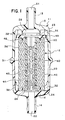
- an exemplary filtering apparatus 10 embodying the present invention generally comprises a housing 11 and a filter arrangement 12 disposed within the housing 11.
- the housing 11 has an inlet 13 and an outlet 14 and defines a fluid flow path through the housing between the inlet 13 and the outlet 14.
- the filter arrangement 12 is positioned in the fluid flow path to remove impurities from fluid flowing through the housing 11.
- the housing may have any suitable configuration and may be fashioned from any appropriately impervious material which is chemically compatible with the fluid to be filtered.
- the housing 11 is preferably fashioned in a generally cylindrical configuration from a polymeric material, including a thermoplastic such as polyvinylchloride, acrylonitrile butadiene styrene, polyethylene, polypropylene, or polyamide.
- the housing 11 has an inlet end portion 15 which includes the inlet 13, an outlet end portion 16 which includes the outlet 14, and each end portion 15, 16 has a side wall 20 which side walls together substantially extend between the inlet and outlet 13, 14.
- the inlet 13 and the outlet 14 are disposed coaxially with respect to the housing 11 and each may be formed as any suitable connector.
- the inlet and the outlet may be formed as threaded connectors or "quick release" connectors.
- the inlet 13 and the outlet 14 are formed as hose connectors, each comprising a cylindrical protrusion having an exterior lip and a respective central opening 21, 22 which provides communication between the outside and inside of the housing 11.
- the housing is formed from first and second body portions, preferably identical body portions.
- the housing 11 is formed from an inlet body portion 23 and an identical outlet body portion 24 joined to one another at join faces 30, 31 extending circumferentially about the side wall 20 of the housing 11.
- Each body portion 23, 24 includes one end portion 15, 16 of the housing 11 and a seal edge 25, 26 which projects axially inwardly from the interior of the housing 11.
- each seal edge 25, 26 is formed integrally with the housing 11 and has a generally annular configuration encircling the opening 21, 22 of the inlet 13 or the outlet 14 respectively.
- the filtering apparatus further includes a structure for properly positioning and securing the filter arrangement within the housing.
- This structure may be variously configured including, for example, as an annular boss along the interior of the housing.
- the housing 11 includes a plurality of ribs 32 positioned within each end portion 15, 16 of the housing 11, preferably integrally formed with the housing 11.
- the ribs may be formed in a variety of shapes, each rib 32 of the exemplary filtering apparatus 10 has a "stepped" configuration including three different surfaces.
- the first surface 33 of each rib is nearest the respective outer end of the end portion 15, 16 of the housing 11 at which the rib 32 is located and faces substantially radially inwardly.
- the second surface 34 is generally perpendicular to the first surface 33 and faces substantially axially inwardly.
- the third surface 35 is generally perpendicular to the second surface 34, is closer to the side wall 20 of the housing 11 than the first surface 33, and faces susbtantially radially inwardly.
- the filter arrangement may be variously configured without departing from the scope of the invention.
- it may be designed for axial flow or radial inside-out flow; it may include a pleated element of membrane sheeting or a porous membrane of annular section; or it may include a sorbent material for sorbing certain impurities.
- the filter arrangement 12 includes a hollow, generally cylindrical filter element 36 coaxially disposed within the housing 11 and designed for radial outside-in flow.
- the filter element 36 includes first and second porous plane end surfaces 40, 41, an outer cylindrical surface 42 which communicates with the inlet 13, and an inner cylindrical surface 43 which communicates with the outlet 14.
- the filter element 36 may comprise any suitable filter medium and may have any appropriate absolute pore rating for removing impurities.
- the filter medium may comprise an annular section mass of polymeric microfibers, such as that available from Pall Corporation under the trademark PROFILE, and may have an absolute pore rating in the range from about 90 microns to less than 1 micron.
- the exemplary filtering apparatus 10 also includes a perforated core 44 and a blind end cap 45.
- the perforate core 44 may be positioned circumjacent to the inner surface 43 of the filter element 36 to support the filter element 36 against the forces associated with the pressure drop across the filter element 36.
- the blind end cap 45 caps the first end surface 40 of the filter element 36.
- the blind end cap includes a generally annular seal edge 46 which protrudes into the first end surface 40 of the filter element 36, opposing the seal edge 26 on the outlet end portion 16 of the housing 11 which protrudes into the second end surface 41 of the filter element 36.
- the end cap 45 also includes a centring tongue 50 which fits within the core 44 to centre the end cap 45 on the first end surface 40 of the filter element 36.
- the filter arrangement 12 is secured within the housing 11 solely by mechanical compression between first and second surfaces of the housing 11.
- the filter arrangement 12 is secured between a first surface which comprises the plurality of second surfaces 34 of the ribs 32 within the inlet end portion 15 of the housing 11 and a second surface which comprises the interior surface of the outlet end portion 16 of the housing 11.
- the end cap 45 abuts but is not joined to the plurality of second surfaces 34 of the ribs 32 while the second end surface 41 of the filter element abuts but is not joined to the interior surface of the outlet end portion 16 of the housing 11. Further, the end cap 45 abuts but is not joined to the first end surface 40 of the filter element 36.
- An exemplary method of manufacturing a filtering apparatus generally comprises bringing one end of a filter element into contact with a body portion having a seal edge which projects toward that end of the filter element and bringing the other end of the filter element into contact with an end cap having a seal edge which projects toward that end of the filter element.
- the outlet body portion 24 of the housing 11 may be placed in the lower rest of a hot plate welding machine with the join face 31 of the outlet body portion 24 facing upwardly.
- the filter element 36 may then be placed in the outlet body portion 24 with the second end surface 41 of the filter element resting on the seal edge 26 of the outlet body portion 24.
- the first surfaces 33 of the ribs 32 on the outlet body portion 24 serve to centre the filter element coaxially within the housing 11.
- the end cap 45 may then be placed on the first end surface 40 of the filter element 36 with the centring tongue 50 positioned in the core 44 and the seal edge 46 of the end cap 45 resting on the first end surface 40 of the filter element 36.
- the welding machine may include a support rod which extends through the outlet opening 22 and the outlet 14 and through the centre of the core 44 and engages the centring tongue 50 of the end cap 45.
- the inlet body portion 23 may be placed in the lower rest of a hot plate welding machine with the join face 30 facing upwardly.
- the blind end cap 45 may then be placed on the plurality of second surfaces 34 of the ribs 32 on the inlet body portion 23.
- the third surfaces 35 of the ribs 32 serve to centre the end cap 45 in the inlet body portion 23.
- the first end 40 of the filter element 36 may then be placed on the seal edge 46 of the end cap 45 with the centring tongue 50 positioned within the core 44.
- the exemplary method of manufacturing the filtering apparatus further comprises joining the first body portion to a second body portion to form a housing, driving the seal edges into the respective ends of the filter element, and securing the end cap and the filter element within the housing solely by mechanical compression between the body portions.
- the inlet body portion 23 may be placed over the outlet body portion 24 with the respective join faces 30, 31 facing one another.
- a hot plate may be brought into contact with the join faces 30, 31 for a predetermined amount of time sufficient to soften or melt the join faces 30, 31.
- the join faces 30, 31 are then forced together, joining the inlet body portion 23 to the outlet body portion 24.
- the outlet body portion 24 may be placed over the inlet body portion 23 with the respective join faces 31, 30 facing one another.
- a hot plate may be brought into contact with the join faces 31, 30 for a predetermined amount of time sufficient to soften or melt the join faces 31, 30.
- the join faces 31, 30 are then forced together, joining the outlet body portion 24 to the inlet body portion 23.
- the join faces 30, 31 may alternatively be joined in any other suitable manner including, for example, sonic welding, vibration welding, spin bonding, bonding by an adhesive, or molding a circumferential collar around the join faces 30, 31.
- the filter arrangement 12 is compressed between the inlet and outlet body portions 23, 24, driving the seal edge 46 of the end cap 45 and the seal edge 26 of the outlet body portion 24 into the first and second ends 40, 41 of the filter element 36.
- the seal edge 46 of the end cap 45 may have been driven into the first end 40 of the filter ele ment 36 before the filter element 36 was placed in the outlet body portion 24.
- the housing 11 is dimensioned such that once the join faces 30, 31 are joined to one another, the filter arrangement 12 is tightly secured solely by mechanical compression between the inlet and outlet body portions 23, 24.
- the filter arrangement 12 is tightly secured between the second surfaces 35 of the ribs 32 in the inlet body portion 23 and the interior surface of the outlet end 16 of the housing 11 with the first and second ends 40, 41 of the filter element 36 tightly wedged against the end cap 45 and the outlet end 16 of the housing 11.
- the hose connectors of the inlet 13 and the outlet 14 of the exemplary filtering apparatus 10 may be attached to hoses (not shown) of a fluid system. Fluid to be filtered may then be directed into the exemplary filtering apparatus 10 to the inlet 13 where it is diverted by the end cap 45 to the outer, upstream surface 42 of the filter element 36. The fluid is then forced radially inwardly through the filter medium of the filter element 36 where the impurities are removed from the fluid. The fluid is prevented from flowing around the first end 40 of the filter element 36 and bypassing the filter medium of the filter element 36 by the seal formed between the first end 40 of the filter element 36 and the end cap 45.
- the fluid is prevented from flowing around the second end 41 of the filter element 36 and bypassing the filter medium of the filter element 36 by the seal formed between the second end 41 of the filter element 36 and the outlet end 16 of the hous ing 11.
- the filtrate exits the filter element 36 at the inner, downstream surface 43, passes through the perforated core 44, and then flows axially through the outlet 14.
- a filtering apparatus may be used in a variety of applications.
- the filtering apparatus may be used to filter liquids such as water and, specifcially, as a prefilter for the water supply of a dialysis machine. Because the filtering apparatus is relatively inexpensive, it may be frequently replaced to prevent the accumulation of impurities, such as harmful bacteria. More generally, the filtering apparatus may be used as a filter for drink dispensers or as a general purpose filter for filtering a variety of fluids in laboratories.
- Filters sold under the trade mark PROFILE have the following essential characteristics: "A cylindrical fibrous structure comprising a fibrous mass of non-woven, synthetic, polymeric microfibers, said microfibers being substantially free of fiber-to-fiber bonding and secured to each other by mechanical entanglement or intertwining, and said fibrous mass having a substantially constant voids volume over at least a substantial portion thereof as measured in the radial direction, the constant voids volume being combined with graded fiber cross-section whereby a varying pore size is provided over said substantial portion.”
Landscapes
- Engineering & Computer Science (AREA)
- Mechanical Engineering (AREA)
- Chemical & Material Sciences (AREA)
- Chemical Kinetics & Catalysis (AREA)
- Separation Using Semi-Permeable Membranes (AREA)
- Filtering Of Dispersed Particles In Gases (AREA)
- Filtration Of Liquid (AREA)
Priority Applications (1)
| Application Number | Priority Date | Filing Date | Title |
|---|---|---|---|
| EP19940201137 EP0613710A1 (de) | 1988-05-27 | 1989-05-25 | Filtervorrichtung |
Applications Claiming Priority (2)
| Application Number | Priority Date | Filing Date | Title |
|---|---|---|---|
| GB8812672A GB2218919B (en) | 1988-05-27 | 1988-05-27 | Filtering apparatus |
| GB8812672 | 1988-05-27 |
Related Child Applications (2)
| Application Number | Title | Priority Date | Filing Date |
|---|---|---|---|
| EP94201137.0 Division-Into | 1989-05-25 | ||
| EP19940201137 Division EP0613710A1 (de) | 1988-05-27 | 1989-05-25 | Filtervorrichtung |
Publications (3)
| Publication Number | Publication Date |
|---|---|
| EP0343976A2 true EP0343976A2 (de) | 1989-11-29 |
| EP0343976A3 EP0343976A3 (de) | 1990-07-25 |
| EP0343976B1 EP0343976B1 (de) | 1998-01-14 |
Family
ID=10637703
Family Applications (2)
| Application Number | Title | Priority Date | Filing Date |
|---|---|---|---|
| EP19940201137 Withdrawn EP0613710A1 (de) | 1988-05-27 | 1989-05-25 | Filtervorrichtung |
| EP19890305283 Expired - Lifetime EP0343976B1 (de) | 1988-05-27 | 1989-05-25 | Filterapparat |
Family Applications Before (1)
| Application Number | Title | Priority Date | Filing Date |
|---|---|---|---|
| EP19940201137 Withdrawn EP0613710A1 (de) | 1988-05-27 | 1989-05-25 | Filtervorrichtung |
Country Status (5)
| Country | Link |
|---|---|
| EP (2) | EP0613710A1 (de) |
| JP (1) | JP2561957B2 (de) |
| CA (1) | CA1339951C (de) |
| DE (1) | DE68928539T2 (de) |
| GB (1) | GB2218919B (de) |
Cited By (4)
| Publication number | Priority date | Publication date | Assignee | Title |
|---|---|---|---|---|
| EP0442069A3 (en) * | 1990-02-16 | 1991-10-23 | Bayer Ag | Filter candle with filter sock |
| EP0408377A3 (en) * | 1989-07-13 | 1992-03-04 | Pall Corporation | Filter assembly |
| WO2001087455A1 (en) * | 2000-05-15 | 2001-11-22 | Honeywell International Inc. | Plastic filter housing having a weld seam skewed with regard to a plane normal to the longitudinal axis of the housing |
| EP2460589B1 (de) * | 2010-12-03 | 2018-10-10 | Samsung Electronics Co., Ltd. | Hydrodynamischer Filter, Filtervorrichtung damit und Filterverfahren mit dem hydrodynamischen Filter |
Families Citing this family (11)
| Publication number | Priority date | Publication date | Assignee | Title |
|---|---|---|---|---|
| DE29504607U1 (de) * | 1995-03-17 | 1996-07-11 | Robert Bosch Gmbh, 70469 Stuttgart | Kraftstoffilter mit einem Gehäuse aus Aluminium |
| AU729705B2 (en) * | 1996-11-26 | 2001-02-08 | 3M Innovative Properties Company | Encapsulated lenticular filter cartridge |
| US5965019A (en) * | 1996-11-26 | 1999-10-12 | Cuno Incorporated | Encapsulated lenticular filter cartridge |
| AU759630B2 (en) * | 1996-11-26 | 2003-04-17 | 3M Innovative Properties Company | Encapsulated lenticular filter cartridge |
| NL1012700C1 (nl) * | 1999-07-26 | 1999-09-16 | Triad Holding Bv | Filterinrichting voor microfiltrering van olie, in het bijzonder voor toepassing bij motoren, alsmede filterhuis bestemd voor een dergelijke filterinrichting. |
| AU2001274291A1 (en) * | 2000-06-23 | 2002-01-02 | Pall Corporation | Filter assemblies |
| US6835236B2 (en) | 2002-01-25 | 2004-12-28 | Sporlan Valve Company | Molded core filter drier with filter media molded to core |
| CN1303384C (zh) * | 2002-01-25 | 2007-03-07 | 斯伯兰阀门公司 | 模制芯干燥过滤器 |
| US6835235B2 (en) | 2002-01-25 | 2004-12-28 | Sporlan Valve Company | Molded core filter drier with filter media molded to core for use in heat pump systems |
| CN110787540A (zh) * | 2019-12-03 | 2020-02-14 | 南通兆华机械制造有限公司 | 一种内面套膜的gl过滤器 |
| DE102021206215A1 (de) | 2021-06-17 | 2022-12-22 | Mahle International Gmbh | Partikelfilter |
Family Cites Families (13)
| Publication number | Priority date | Publication date | Assignee | Title |
|---|---|---|---|---|
| GB841818A (en) * | 1958-07-09 | 1960-07-20 | Fram Corp | Improvements relating to liquid filters |
| US3355863A (en) * | 1966-03-08 | 1967-12-05 | Gen Motors Corp | Air cleaner and silencer assemnbly |
| GB1201156A (en) * | 1966-11-10 | 1970-08-05 | W & R Balston Ltd | Filter apparatus |
| US3891416A (en) * | 1973-07-20 | 1975-06-24 | Baxter Laboratories Inc | Cardiotomy reservoir |
| US3932153A (en) * | 1974-02-14 | 1976-01-13 | John Byrns | Nebulizer bacteria filter |
| US3920553A (en) * | 1974-06-27 | 1975-11-18 | Amf Inc | Positioning device for filter cartridge assembly |
| US4062781A (en) * | 1976-06-04 | 1977-12-13 | Whatman Reeve Angel Limited | Disposable filter with interchangeable end elements |
| DE2940144A1 (de) * | 1979-10-03 | 1981-04-16 | Elektro-Stahlbau H.J. Behncke, 8011 Putzbrunn | Trinkwasser-feinfilter |
| GB2094652B (en) * | 1981-03-17 | 1985-01-09 | Frantz Filters Inc | Improved axial flow oil filter |
| EP0139639A1 (de) * | 1983-03-16 | 1985-05-08 | Whatman Reeve Angel Plc | Filterpatrone mit endkappe |
| GB2181967B (en) * | 1985-10-02 | 1989-09-27 | Boc Health Care | Scavenging and filtration apparatus |
| US4728421A (en) * | 1986-05-14 | 1988-03-01 | Penguin Pumps, Inc. | Filter apparatus for utilization with hollow cylindrical filter elements |
| GB8622706D0 (en) * | 1986-09-20 | 1986-10-29 | Domnick Hunter Filters Ltd | Filter assembly |
-
1988
- 1988-05-27 GB GB8812672A patent/GB2218919B/en not_active Expired - Lifetime
-
1989
- 1989-05-25 EP EP19940201137 patent/EP0613710A1/de not_active Withdrawn
- 1989-05-25 EP EP19890305283 patent/EP0343976B1/de not_active Expired - Lifetime
- 1989-05-25 DE DE68928539T patent/DE68928539T2/de not_active Expired - Fee Related
- 1989-05-26 CA CA 600847 patent/CA1339951C/en not_active Expired - Fee Related
- 1989-05-29 JP JP1135707A patent/JP2561957B2/ja not_active Expired - Fee Related
Cited By (5)
| Publication number | Priority date | Publication date | Assignee | Title |
|---|---|---|---|---|
| EP0408377A3 (en) * | 1989-07-13 | 1992-03-04 | Pall Corporation | Filter assembly |
| EP0442069A3 (en) * | 1990-02-16 | 1991-10-23 | Bayer Ag | Filter candle with filter sock |
| WO2001087455A1 (en) * | 2000-05-15 | 2001-11-22 | Honeywell International Inc. | Plastic filter housing having a weld seam skewed with regard to a plane normal to the longitudinal axis of the housing |
| US6651823B1 (en) | 2000-05-15 | 2003-11-25 | Honeywell International Inc. | Plastic filter housing formed from multiple sections and having a skewed weld seam, and filter incorporating same |
| EP2460589B1 (de) * | 2010-12-03 | 2018-10-10 | Samsung Electronics Co., Ltd. | Hydrodynamischer Filter, Filtervorrichtung damit und Filterverfahren mit dem hydrodynamischen Filter |
Also Published As
| Publication number | Publication date |
|---|---|
| GB2218919B (en) | 1993-01-13 |
| GB2218919A (en) | 1989-11-29 |
| DE68928539T2 (de) | 1998-06-18 |
| EP0343976B1 (de) | 1998-01-14 |
| EP0343976A3 (de) | 1990-07-25 |
| CA1339951C (en) | 1998-07-14 |
| GB8812672D0 (en) | 1988-06-29 |
| JPH0263508A (ja) | 1990-03-02 |
| JP2561957B2 (ja) | 1996-12-11 |
| DE68928539D1 (de) | 1998-02-19 |
| EP0613710A1 (de) | 1994-09-07 |
Similar Documents
| Publication | Publication Date | Title |
|---|---|---|
| US5290445A (en) | Filtering apparatus | |
| EP0343976B1 (de) | Filterapparat | |
| US4501663A (en) | Filter cartridges and methods and components for making them | |
| US6568539B1 (en) | Renewable filter with a bypass valve | |
| CA2230590C (en) | An in-line blood filtration device | |
| JPH08506996A (ja) | フィルタ組立体 | |
| CA1148094A (en) | Filter cartridges and methods and components for making them | |
| US20110259812A1 (en) | Filter element and seal therefor | |
| CA2122759A1 (en) | Oil filter with inner and outer coaxial filter elements | |
| EP0929355A1 (de) | Anordnung mit sich ausdehnbarer, eingeschlossener filterkartusche | |
| US6156198A (en) | Filter element for a fluid filter | |
| EP0078419B1 (de) | Pharmazeutische Wegwerffilteranordnung | |
| EP3928849B1 (de) | Filteranordnung mit vorfiltrierungsfilterelement und filtervorrichtung | |
| US6739459B1 (en) | Filter element including bonded end caps and support core | |
| US5776342A (en) | Filter assembly | |
| EP1096983A1 (de) | Filterelement und verfahren zu seiner herstellung | |
| US4732677A (en) | Thermally formed stacked disc filter | |
| GB2254268A (en) | Filter | |
| US7407057B2 (en) | Plastic transmission filter | |
| US5017287A (en) | Dual cup-shaped supporting filter body | |
| EP1562687B1 (de) | Kunststoffgetriebefilter | |
| JPH08168656A (ja) | フィルタ−エレメント組立用部材 |
Legal Events
| Date | Code | Title | Description |
|---|---|---|---|
| PUAI | Public reference made under article 153(3) epc to a published international application that has entered the european phase |
Free format text: ORIGINAL CODE: 0009012 |
|
| AK | Designated contracting states |
Kind code of ref document: A2 Designated state(s): DE FR IT |
|
| PUAL | Search report despatched |
Free format text: ORIGINAL CODE: 0009013 |
|
| AK | Designated contracting states |
Kind code of ref document: A3 Designated state(s): DE FR IT |
|
| 17P | Request for examination filed |
Effective date: 19901220 |
|
| 17Q | First examination report despatched |
Effective date: 19920415 |
|
| GRAG | Despatch of communication of intention to grant |
Free format text: ORIGINAL CODE: EPIDOS AGRA |
|
| GRAG | Despatch of communication of intention to grant |
Free format text: ORIGINAL CODE: EPIDOS AGRA |
|
| GRAH | Despatch of communication of intention to grant a patent |
Free format text: ORIGINAL CODE: EPIDOS IGRA |
|
| GRAH | Despatch of communication of intention to grant a patent |
Free format text: ORIGINAL CODE: EPIDOS IGRA |
|
| GRAA | (expected) grant |
Free format text: ORIGINAL CODE: 0009210 |
|
| DX | Miscellaneous (deleted) | ||
| AK | Designated contracting states |
Kind code of ref document: B1 Designated state(s): DE FR IT |
|
| REF | Corresponds to: |
Ref document number: 68928539 Country of ref document: DE Date of ref document: 19980219 |
|
| ITF | It: translation for a ep patent filed | ||
| ET | Fr: translation filed | ||
| PLBE | No opposition filed within time limit |
Free format text: ORIGINAL CODE: 0009261 |
|
| STAA | Information on the status of an ep patent application or granted ep patent |
Free format text: STATUS: NO OPPOSITION FILED WITHIN TIME LIMIT |
|
| 26N | No opposition filed | ||
| PGFP | Annual fee paid to national office [announced via postgrant information from national office to epo] |
Ref country code: DE Payment date: 20070517 Year of fee payment: 19 |
|
| PGFP | Annual fee paid to national office [announced via postgrant information from national office to epo] |
Ref country code: IT Payment date: 20070525 Year of fee payment: 19 |
|
| PGFP | Annual fee paid to national office [announced via postgrant information from national office to epo] |
Ref country code: FR Payment date: 20070510 Year of fee payment: 19 |
|
| REG | Reference to a national code |
Ref country code: FR Ref legal event code: ST Effective date: 20090119 |
|
| PG25 | Lapsed in a contracting state [announced via postgrant information from national office to epo] |
Ref country code: FR Free format text: LAPSE BECAUSE OF NON-PAYMENT OF DUE FEES Effective date: 20080602 Ref country code: DE Free format text: LAPSE BECAUSE OF NON-PAYMENT OF DUE FEES Effective date: 20081202 |
|
| PG25 | Lapsed in a contracting state [announced via postgrant information from national office to epo] |
Ref country code: IT Free format text: LAPSE BECAUSE OF NON-PAYMENT OF DUE FEES Effective date: 20080525 |