EP0343964B1 - Verbindungsvorrichtung für optische Fasern - Google Patents
Verbindungsvorrichtung für optische Fasern Download PDFInfo
- Publication number
- EP0343964B1 EP0343964B1 EP89305262A EP89305262A EP0343964B1 EP 0343964 B1 EP0343964 B1 EP 0343964B1 EP 89305262 A EP89305262 A EP 89305262A EP 89305262 A EP89305262 A EP 89305262A EP 0343964 B1 EP0343964 B1 EP 0343964B1
- Authority
- EP
- European Patent Office
- Prior art keywords
- optical fiber
- housing
- slide
- adjacent
- free end
- Prior art date
- Legal status (The legal status is an assumption and is not a legal conclusion. Google has not performed a legal analysis and makes no representation as to the accuracy of the status listed.)
- Expired - Lifetime
Links
- 239000013307 optical fiber Substances 0.000 title claims description 99
- 230000003287 optical effect Effects 0.000 description 3
- 230000005693 optoelectronics Effects 0.000 description 3
- 238000010276 construction Methods 0.000 description 2
- 239000011521 glass Substances 0.000 description 2
- DHKHKXVYLBGOIT-UHFFFAOYSA-N 1,1-Diethoxyethane Chemical compound CCOC(C)OCC DHKHKXVYLBGOIT-UHFFFAOYSA-N 0.000 description 1
- 239000004697 Polyetherimide Substances 0.000 description 1
- 229910000831 Steel Inorganic materials 0.000 description 1
- 229920004738 ULTEM® Polymers 0.000 description 1
- 239000011354 acetal resin Substances 0.000 description 1
- 230000002238 attenuated effect Effects 0.000 description 1
- DMFGNRRURHSENX-UHFFFAOYSA-N beryllium copper Chemical group [Be].[Cu] DMFGNRRURHSENX-UHFFFAOYSA-N 0.000 description 1
- 230000000295 complement effect Effects 0.000 description 1
- 230000006835 compression Effects 0.000 description 1
- 238000007906 compression Methods 0.000 description 1
- 229920006351 engineering plastic Polymers 0.000 description 1
- 238000004519 manufacturing process Methods 0.000 description 1
- 239000000463 material Substances 0.000 description 1
- 239000013308 plastic optical fiber Substances 0.000 description 1
- 229920002492 poly(sulfone) Polymers 0.000 description 1
- 229920001601 polyetherimide Polymers 0.000 description 1
- 229920006324 polyoxymethylene Polymers 0.000 description 1
- 230000001681 protective effect Effects 0.000 description 1
- 239000011347 resin Substances 0.000 description 1
- 229920005989 resin Polymers 0.000 description 1
- 239000004065 semiconductor Substances 0.000 description 1
- 239000010959 steel Substances 0.000 description 1
Images

Classifications
-
- G—PHYSICS
- G02—OPTICS
- G02B—OPTICAL ELEMENTS, SYSTEMS OR APPARATUS
- G02B6/00—Light guides; Structural details of arrangements comprising light guides and other optical elements, e.g. couplings
- G02B6/24—Coupling light guides
- G02B6/42—Coupling light guides with opto-electronic elements
- G02B6/4292—Coupling light guides with opto-electronic elements the light guide being disconnectable from the opto-electronic element, e.g. mutually self aligning arrangements
-
- G—PHYSICS
- G02—OPTICS
- G02B—OPTICAL ELEMENTS, SYSTEMS OR APPARATUS
- G02B6/00—Light guides; Structural details of arrangements comprising light guides and other optical elements, e.g. couplings
- G02B6/24—Coupling light guides
- G02B6/36—Mechanical coupling means
- G02B6/38—Mechanical coupling means having fibre to fibre mating means
- G02B6/3801—Permanent connections, i.e. wherein fibres are kept aligned by mechanical means
- G02B6/3806—Semi-permanent connections, i.e. wherein the mechanical means keeping the fibres aligned allow for removal of the fibres
-
- G—PHYSICS
- G02—OPTICS
- G02B—OPTICAL ELEMENTS, SYSTEMS OR APPARATUS
- G02B6/00—Light guides; Structural details of arrangements comprising light guides and other optical elements, e.g. couplings
- G02B6/24—Coupling light guides
- G02B6/36—Mechanical coupling means
- G02B6/38—Mechanical coupling means having fibre to fibre mating means
- G02B6/3807—Dismountable connectors, i.e. comprising plugs
- G02B6/3833—Details of mounting fibres in ferrules; Assembly methods; Manufacture
- G02B6/3834—Means for centering or aligning the light guide within the ferrule
- G02B6/3838—Means for centering or aligning the light guide within the ferrule using grooves for light guides
-
- G—PHYSICS
- G02—OPTICS
- G02B—OPTICAL ELEMENTS, SYSTEMS OR APPARATUS
- G02B6/00—Light guides; Structural details of arrangements comprising light guides and other optical elements, e.g. couplings
- G02B6/24—Coupling light guides
- G02B6/36—Mechanical coupling means
- G02B6/3628—Mechanical coupling means for mounting fibres to supporting carriers
- G02B6/3648—Supporting carriers of a microbench type, i.e. with micromachined additional mechanical structures
- G02B6/3652—Supporting carriers of a microbench type, i.e. with micromachined additional mechanical structures the additional structures being prepositioning mounting areas, allowing only movement in one dimension, e.g. grooves, trenches or vias in the microbench surface, i.e. self aligning supporting carriers
-
- G—PHYSICS
- G02—OPTICS
- G02B—OPTICAL ELEMENTS, SYSTEMS OR APPARATUS
- G02B6/00—Light guides; Structural details of arrangements comprising light guides and other optical elements, e.g. couplings
- G02B6/24—Coupling light guides
- G02B6/36—Mechanical coupling means
- G02B6/3628—Mechanical coupling means for mounting fibres to supporting carriers
- G02B6/3684—Mechanical coupling means for mounting fibres to supporting carriers characterised by the manufacturing process of surface profiling of the supporting carrier
- G02B6/3696—Mechanical coupling means for mounting fibres to supporting carriers characterised by the manufacturing process of surface profiling of the supporting carrier by moulding, e.g. injection moulding, casting, embossing, stamping, stenciling, printing, or with metallic mould insert manufacturing using LIGA or MIGA techniques
Definitions
- the invention concerns optical fiber connectors such as can coaxially interconnect free ends of two optical fibers or can connect an optical fiber to an opto-electronic element.
- the invention is particularly concerned with multiple optical connectors.
- Prior optical fiber connectors tend to be expensive, often requiring mechanical elements to be secured permanently to the free ends of the optical fibers, followed by attaching each such element either to a complementary element or to a fixture. Doing so can require special tools. See, for example, Thomas & Betts Corp. Cat. No. 93800SK.
- a relatively inexpensive optical fiber connector can be constructed as disclosed in U.S. Pat. No. 4,470,180 (Blomgren).
- a preferred Blomgren connector includes an elongated mount that is encompassed by a resiliently deformable housing which, in its relatively undeformed state, can pinch an optical fiber against a groove in the surface of the mount. When compressed, the housing is deformed to permit an optical fiber to be positioned on the mount or to be withdrawn. When the compression is released with a free end of an optical fiber positioned on the mount, the housing returns to its undeformed state to grip the free end as shown in Fig. 6B of the Blomgren patent. In the same way, a second optical fiber can be coaxially interconnected with the first in abutting relation as shown in Blomgren Fig. 6C.
- a mechanical splice now on the market (“Dorran/3M” mechanical splice) which employs the Blomgren Optical fiber connector has a strain-relief chock that grips a protective covering or buffer of each connected optical fiber to ensure against accidental loosening.
- FR-A-2560392 discloses an optical fiber connector comprising a mount having a groove and encompassed by a substantially cylindrical, resiliently deformable housing that, when substantially undeformed, can pinch the free end of an optical fiber against the groove or, when deformed, can release the free end.
- the reference further discloses means for deforming the housing and means for gripping an intermediate portion of the optical fiber, the free end of which is being pinched by the housing.
- an optical fiber connector including: an elongate mount having a longitudinal groove for receiving the free end of at least one optical fiber and encompassed by a normally substantially cylindrical, resiliently deformable housing that, when substantially undeformed, can pinch the free end of the optical fiber against the groove or, when deformed, can permit the optical fiber to be inserted into or removed from the groove, means for deforming said housing, and means for gripping an intermediate portion of the optical fiber when its free end is being pinched by the housing, characterised by the fact that said connector further comprises: a block provided with an elongate cavity in which said elongate mount encompassed by said cylindrical housing is lodged, said block being furthermore provided with a longitudinal channel extending adjacent and substantially parallel to said elongate cavity, and at least one slide positioned within said channel and movable therein between an advanced position adjacent said housing and a retracted position adjacent said gripping means, so as respectively to actuate said means for deforming said housing when moved to said advanced position and said means for gripping said intermediate
- the slide preferably is formed so that it can be moved with one finger between its advanced and retracted positions, thus making it unnecessary to employ a separate tool for connecting or disconnecting optical fibers.
- the novel optical fiber connector To enable the novel optical fiber connector to connect two optical fibers coaxially, its housing should either be split or sufficiently resilient so that when one end of the housing is deformed to release one of a pair of interconnected optical fibers, the other end of the housing can continue to pinch the other of the pair.
- the block of such a connector should include two movable devices as described, each acting on one of the abutting optical fibers.
- the housing is sufficiently transparent to permit one to see that the end of an optical fiber extends approximately to the center of the mount when the other half of the connector is empty. When one of the optical fibers is in position, it acts as a stop for the coaxial optical fiber.
- Such an optical fiber connector like that of the Blomgren patent, is inexpensive, easy to use and does not require any auxiliary tool.
- the novel optical connector can be inexpensively constructed to form coaxial connections between a large number of pairs of optical fibers while virtually assuring that they will not become loosened accidentally.
- Both the compressing of the housing and the gripping of an intermediate portion of an optical fiber is accomplished by a single protrusion from the aforementioned slide.
- That protrusion can be a ball bearing held by a pocket of the slide.
- the block can carry a lever that is centrally pivoted so that the end of the lever can either compress the housing or can grip an intermediate portion of the optical fiber when the housing is not being compressed.
- This intermediate gripping ensures that the free end of the optical fiber is securely held in position, thus providing a reliable connection until the slide or lever is operated to release the optical fiber.
- the connector can incorporate means for slightly detuning the splice to attenuate transmitted signals.
- the longitudinal groove in the mount can have a central discontinuity to position the abutting optical fibers to be slightly out of perfect coaxial alignment, thus slightly attenuating light transmitted through the connector. Doing so is desirable whenever there is a danger that the light signals being transmitted might be so intense as to cause a detector to go into saturation.
- the mount can be quickly and inexpensively changed from time to time to reduce the attenuation, thus keeping the transmitted signal levels substantially constant.
- the present invention also concerns an assembly of optical fiber connectors as defined in claim 10.
- a block 10 holds an array of optical fiber connectors 12, four of which are shown wholly or in part, each of identical construction.
- the block 10 has a cavity 14 in which a mount 16 of elliptical cross section is lodged to position with precision a longitudinal v-groove 18 in the mount at one end of its major axis. Free ends of a pair of optical fibers 20 and 21 are nested in each of the V-grooves in abutting coaxial relation.
- a deformable housing 22 which, when substantially not deformed, is cylindrical and pinches both optical fibers 20 and 21 against the longitudinal v-groove 18.
- Each of the connectors 12 has a pair of elongated slides 24 and 25, each of which is slidable in an elongated channel 28 formed in the block 10.
- Each of the slides 24 and 25 is shown in its retracted position in Fig. 1, and a slide 25 is in its advanced position in Fig. 2.
- Each of the slides 24 and 25 has a pocket containing a ball 30 and 31, respectively, that protrudes from one side of the slide to ride against a wall 32 of the channel 28.
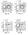
- a slide 25 When a slide 25 is in its advanced position as shown in Fig. 2, its ball 31 presses an upstanding lug 35 against the housing 22, deforming that portion of the housing as shown in Fig. 4, thus lifting the housing to free the optical fiber 21 to permit it either to be inserted into or removed from the v-groove 18 of the mount 16.
- the housing 22 is released to assume its normally substantially cylindrical shape and thus pinch the optical fiber 21 against the v-groove of the mount 16 as shown in Fig. 5.
- Such retraction causes one corner of the slide 25 and its ball 31 to press against a slanted surface 37 of a post 39.
- the post in turn is pressed against an intermediate portion of the optical fiber 21, thus locking the optical fiber securely in place until the slide is again moved to its advanced position.
- each of slides 24 and 25 has an upstanding projection 40 and 41, respectively, to permit a user to slide them along the channel 28 with the fingertip. Hence, no tool is required to connect optical fibers into the illustrated optical fiber connectors. Movement of the slides is limited by the ends 42 and 43 of each of the channels 28, and each slide acts as a stop for the other, thus permitting only one of the two connected optical fibers to be manipulated at one time.
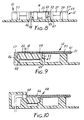
- each of the mounts 16 is lodged in the block 10 is shown in Figs. 8 and 9. As seen in Fig. 8, the ends of each housing 22 are cut away to permit a shoulder 46 and 47 at each end of the mount 16 to rest on a seat 48 and 49, respectively, formed in the block 10.
- a wall 53 at an end of each cavity 14 and the top surface 55 of the block 10 of each connector are formed with furrows 57 for guiding an optical fiber into each of the optical fiber connectors 12, and each mount 16 at an end of its groove 18 has a bell mouth 59 as seen in Figs. 2 and 9 to enhance threading optical fibers into the v-groove 18.
- Each of the optical fibers 20 and 21 has a buffer 60 and 61, respectively, that is stripped away from that portion of the optical fiber that extends into the V-groove 18 while protecting the portion of the optical fiber that is contacted by one of the posts 39.
- any of the mounts 16 of the illustrated optical fiber connectors can easily be replaced by a mount having a stepped groove so that connected pairs of optical fibers are slightly out of perfect coaxial alignment, thus passing attenuated signals for reasons discussed above.
- an optical fiber connector 64 which is identical in construction to half of one of the optical fiber connectors 12, permits an optical fiber 66 to be connected to an opto-electronic element 68.
- a prototype of the block 10 illustrated in Figs. 1-9 has been constructed to have six optical fiber connectors for six pairs of glass optical fibers, each having a diameter of 125 ⁇ m without the buffer 60 or 61.
- Both the block and the slides 24 and 25 were machined from acetal resin, even though they would in production be more economically molded of a high impact, low creep, engineering plastic such as polyetherimide resin (e.g., "Ultem” from G.E.).
- the housings 22 were cut from extruded polysulfone tubing which has good transparency.
- a useful material for the housings which is not transparent is beryllium copper.
- the balls 30 and 31 were standard steel ball bearings.
Landscapes
- Physics & Mathematics (AREA)
- General Physics & Mathematics (AREA)
- Optics & Photonics (AREA)
- Mechanical Coupling Of Light Guides (AREA)
Claims (10)
- Verbindungsvorrichtung für optische Fasern, dadurch gekennzeichnet, daß die Vorrichtung folgendes umfaßt:
ein längliche Halterung (16) mit einem länglichen Kanal (18) zur Aufnahme des freien Endes (20) von mindestens einer optischen Faser (60) und wobei die Halterung von einem im Normalzustand im wesentlichen zylinderförmigen, elastisch verformbaren Gehäuse (22) eingeschlossen wird, welches, wenn es im wesentlichen unverformt ist, das freie Ende (20) der optischen Faser (60) gegen den Kanal (18) klemmen kann, oder welches, wenn es verformt ist, ermöglichen kann, daß die optische Faser (60) in den Kanal (18) eingeführt werden kann bzw. aus dem Kanal entfernt werden kann,
eine Einrichtung (30, 35) zur Verformung des genannten Gehäuses (22), und
eine Einrichtung (30, 39) zum Greifen eines mittleren Teils der optischen Faser (60), wenn deren freies Ende (20) durch das Gehäuse (22) eingeklemmt wird,
dadurch gekennzeichnet, daß die genannte Verbindungseinrichtung ferner folgendes umfaßt:
einen Block (10), der mit einem länglichen Hohlraum (14) versehen ist, in dem die von dem genannten zylinderförmigen Gehäuse (22) eingeschlossene längliche Halterung (16) angebracht ist, wobei der genannte Block (10) ferner mit einem länglichen Kanal (28) versehen ist, der sich neben und im wesentlichen parallel zu dem genannten länglichen Hohlraum (14) erstreckt, und
mindestens einen Schieber (24), der in dem genannten Kanal (28) positioniert ist und der darin zwischen einer vorgeschobenen Position neben dem genannten Gehäuse (22) und einer zurückgezogenen Position neben der Greifeinrichtung (30, 39) bewegt werden kann, um so entsprechend die Einrichtung (30, 35) zur Verformung des genannten Gehäuses (22) zu betätigen, wenn der Schieber an die vorgeschobene Position bewegt wird und um die genannte Einrichtung (30, 39) zum Greien des genannten mittleren Teils der optischen Faser (60) zu betätigen, wenn der Schieber an die zurückgezogene Position bewegt wird. - Verbindungsvorrichtung für optische Fasern nach Anspruch 1, dadurch gekennzeichnet, daß der Schieber (24) eine Einrichtung (40) umfaßt, mit der der Schieber durch einen Finger zwischen der vorgeschobenen und der zurückgezogenen Position bewegt werden kann.
- Verbindungsvorrichtung für optische Fasern nach Anspruch 1, dadurch gekennzeichnet, daß die Halterung (16) und das Gehäuse (22) so angeordnet sind, daß sie die freien Enden (20, 21) von zwei optischen Fasern (60, 61) unabhängig gegen den Kanal (18) klemmen, und zwar in aneinanderstoßender, koaxialer Beziehung, dadurch gekennzeichnet, daß die genannte Verbindungsvorrichtung für optische Fasern ferner folgendes umfaßt:
einen zweiten Schieber (25), der ebenfalls in dem genannten Kanal (28) positioniert ist und der zwischen einer vorgeschobenen Position neben dem Gehäuse (22) und einer zurückgezogenen Position neben einem mittleren Teil der zweiten optischen Faser (61) bewegt werden kann,
eine zweite Einrichtung (31, 35), die durch die Bewegung des zweiten Schiebers (25) an dessen vorgeschobene Position betätigt wird, um das Gehäuse (22) neben dem freien Ende (21) der zweiten optischen Faser (61) zu verformen, und
eine zweite Einrichtung (31, 39), die durch die Bewegung des zweiten Schiebers (25) an dessen zurückgezogene Position betätigt wird, um den mittleren Teil der genannten zweiten optischen Faser (61) zu greifen. - Verbindungsvorrichtung für optische Fasern nach Anspruch 1, dadurch gekennzeichnet, daß die genannte Einrichtung (30, 35) zur Verformung des Gehäuses einen Ansatz (35) aufweist, der von dem Block (10) zwischen dem genannten Gehäuse (22) und dem genannten Kanal (28) vorsteht, und daß die Einrichtung eine Einrichtung (30) aufweist, die von dem Schieber (24) vorsteht, um den genannten Ansatz (35) gegen das genannte Gehäuse (22) zu drücken, wenn sich der Schieber (24) in dessen vorgeschobenen Position befindet.
- Verbindungsvorrichtung für optische Fasern nach Anspruch 4, dadurch gekennzeichnet, daß die von dem Schieber (24) vorstehende Einrichtung (30) ein Kugellager umfaßt, welches durch eine Tasche des Schiebers gehalten wird.
- Verbindungsvorrichtung für optische Fasern nach Anspruch 1, dadurch gekennzeichnet, daß die genannte Einrichtung (30, 39) zum Greifen des mittleren Teils der optischen Faser (60) einen Pfosten (39) umfaßt, der von dem Block (10) neben dem genannten Kanal in einer von dem Hohlraum (14) entfernten Position vorsteht, und daß die Einrichtung eine Einrichtung (30) aufweist, die von dem Schieber (24) vorsteht, um den genannten Pfosten (39) gegen den genannten mittleren Teil der optischen Faser zu drücken, wobei deren freies Ende durch das Gehäuse eingeklemmt wird.
- Verbindungsvorrichtung für optische Fasern nach Anspruch 6, dadurch gekennzeichnet, daß die Fläche des Pfostens (39), die mit der vorstehenden Einrichtung in Kontakt gerät, zugespitzt ist.
- Verbindungsvorrichtung für optische Fasern nach Anspruch 3, dadurch gekennzeichnet, daß der genannte Block (10) mit einer Mehrzahl von länglichen Hohlräumen (14) ausgebildet ist, von denen jeder eine längliche Halterung (16) lagert, die von einem entsprechenden Gehäuse (22) eingeschlossen wird, sowie ferner mit einer gleichen Anzahl von Kanälen (28) und wobei ein erster (24) und zweiter (25) Schieber beweglich in jedem Kanal (28) positioniert sind.
- Verbindungsvorrichtung für optische Fasern nach Anspruch 8, dadurch gekennzeichnet, daß jedes Gehäuse (22) ausreichend elastisch ist, so daß bei Verformung eines Gehäuseendes, um eine optische Faser (60) eines verbundenen optischen Faserpaares (60, 61) freizugeben, das andere Ende des Gehäuses weiterhin die andere Faser (61) des Paares einklemmt und wobei der genannte Block (10) eine Mehrzahl erster und zweiter Einrichtungen (30, 31, 35, 39) umfaßt, die durch Bewegung eines entsprechenden Schiebers (24, 25) betätigt werden, um das angrenzende Ende des entsprechenden Gehäuses (22) zu verformen, oder um den mittleren Teil einer entsprechenden optischen Faser (60, 61) zu greifen, wobei deren freies Ende (20, 21) durch einen Teil eines entsprechenden Gehäuses (22) eingeklemmt wird.
- Zusammenbau von Verbindungseinrichtungen (12) für optische Fasern, folgendes umfassend:
einen Block (10), der mit einer Mehrzahl von sich parallel erstreckenden, länglichen Hohlräumen (14) versehen ist, sowie mit einer Mehrzahl von länglichen Kanälen (28), von denen sich jeder neben und im wesentlichen parallel zu einem entsprechenden länglichen Hohlraum (14) aus deren Mehrzahl erstreckt;
eine längliche Halterung (16), die entsprechend in jedem Hohlraum (14) der genannten Mehrzahl von Hohlräumen lagert, wobei jeder Halterung (16) einen länglichen V-Kanal (18) zur Aufnahme eines freien Endes (20) von wenigstens einer optischen Faser (60) aufweist, um dieses genau zu positionieren;
ein im Normalzustand im wesentlichen elastisches, zylinderförmiges, verformbares Gehäuse (22), welches jede Halterung (16) einschließt, so daß es, wenn es im wesentlichen unverformt ist, das freie Ende (20) der optischen Faser (60) gegen den V-Kanal (18) drücken kann und wenn es elliptisch verformt ist, ermöglicht, daß die optische Faser (60) in einen Kanal (18) eingeführt werden oder aus diesem entfernt werden kann;
mindestens einen Schieber (24), der entsprechend in jedem Kanal (28) aus der genannten Mehrzahl von Kanälen positioniert ist und der in dem Kanal zwischen einer vorgeschobenen und einer zurückgezogenen Position bewegt werden kann;
einen Ansatz (35), der von dem Block (10) zwischen jedem Kanal (28) und dem angrenzenden Gehäuse (22) vorsteht, gelagert in dem entsprechenden Hohlraum (14); und
einen Pfosten (39), der von dem Block (10) neben jedem Kanal (28) an einer Längsachsenposition vorsteht, die von dem entsprechenden Hohlraum (14) entfernt ist; wobei
jeder Schieber (24) einen Vorsprung (30) aufweist, der, wenn sich der Schieber an dessen vorgeschobenen Position befindet, den genannten Ansatz (35) drückt, um das angrenzende Gehäuse (22) zu verformen und um somit zu ermöglichen, daß das freie Ende (20) der optischen Faser (60) in die entsprechende Halterung (16) eingeführt oder von dieser gelöst werden kann, und wenn sich der Schieber (24) an dessen zurückgezogenen Position befindet, so wird der Pfosten (39) gegen einen mittleren Teil der optischen Faser (60) gedrückt, wenn deren freies Ende (20) von dem Gehäuse (22) eingeklemmt wird.
Applications Claiming Priority (2)
| Application Number | Priority Date | Filing Date | Title |
|---|---|---|---|
| US07/198,872 US4890896A (en) | 1988-05-26 | 1988-05-26 | Connecting device for optical fibers |
| US198872 | 1988-05-26 |
Publications (3)
| Publication Number | Publication Date |
|---|---|
| EP0343964A2 EP0343964A2 (de) | 1989-11-29 |
| EP0343964A3 EP0343964A3 (en) | 1990-08-01 |
| EP0343964B1 true EP0343964B1 (de) | 1993-10-27 |
Family
ID=22735207
Family Applications (1)
| Application Number | Title | Priority Date | Filing Date |
|---|---|---|---|
| EP89305262A Expired - Lifetime EP0343964B1 (de) | 1988-05-26 | 1989-05-24 | Verbindungsvorrichtung für optische Fasern |
Country Status (9)
| Country | Link |
|---|---|
| US (1) | US4890896A (de) |
| EP (1) | EP0343964B1 (de) |
| JP (1) | JPH0224608A (de) |
| AU (1) | AU620616B2 (de) |
| BR (1) | BR8902413A (de) |
| CA (1) | CA1321721C (de) |
| DE (1) | DE68910185T2 (de) |
| ES (1) | ES2045430T3 (de) |
| ZA (1) | ZA893985B (de) |
Families Citing this family (13)
| Publication number | Priority date | Publication date | Assignee | Title |
|---|---|---|---|---|
| US5138681A (en) * | 1988-04-18 | 1992-08-11 | Minnesota Mining And Manufacturing Company | Optical fiber splice |
| US4948224A (en) * | 1989-02-21 | 1990-08-14 | Modrey Henry J | Connector for optical fibers and the like |
| HU213333B (en) * | 1990-01-05 | 1997-05-28 | Minnesota Mining & Mfg | Optical fibre-connector |
| US5392373A (en) * | 1993-11-29 | 1995-02-21 | The Whitaker Corporation | Apparatus for optically coupling an optical fiber to an electro-optic device |
| JP3232845B2 (ja) * | 1994-01-24 | 2001-11-26 | 株式会社村田製作所 | 誘電体共振器装置 |
| US5734775A (en) * | 1996-02-06 | 1998-03-31 | Vidacovich; Kenneth John | Method and system for fiber optic splice activation and deactivation within an optical fiber distribution frame |
| US6404955B1 (en) * | 2001-07-03 | 2002-06-11 | Corning, Incorporated | System and method for fabricating arrayed optical fiber collimators |
| JP2005070507A (ja) * | 2003-08-26 | 2005-03-17 | Sumitomo Electric Ind Ltd | 光モジュール及び光結合調心方法 |
| KR100797652B1 (ko) | 2007-07-03 | 2008-01-24 | 주식회사 옵텔콤 | 광 컨넥터 및 광섬유 케이블 조립방법 |
| CA2734213C (en) | 2008-08-19 | 2018-06-26 | Belden Cdt (Canada) Inc. | Slide actuated field installable fiber optic connector |
| US7957623B2 (en) * | 2008-09-19 | 2011-06-07 | Pyrophotonics Lasers Inc. | Deformable thermal pads for optical fibers |
| MX2014008211A (es) | 2012-01-13 | 2014-08-08 | Afl Telecommunications Llc | Detector de eventos de fibra optica. |
| FR2998662B1 (fr) * | 2012-11-23 | 2019-10-25 | Airbus Operations | Dispositif de mesure de deformation et implantation d'un tel dispositif dans un element |
Family Cites Families (9)
| Publication number | Priority date | Publication date | Assignee | Title |
|---|---|---|---|---|
| FR2104693B1 (de) * | 1970-07-30 | 1974-11-08 | Jeumont Schneider | |
| FR2382017A1 (fr) * | 1977-02-23 | 1978-09-22 | Socapex | Connecteur pour monofibre optique |
| FR2420777A1 (fr) * | 1978-03-24 | 1979-10-19 | Lignes Telegraph Telephon | Procede et appareillage de raccordement de cables a fibres optiques |
| AU510179B2 (en) * | 1978-06-12 | 1980-06-12 | Thomas & Betts Corporation | Fiber optic splice |
| US4470180A (en) * | 1981-05-26 | 1984-09-11 | Minnesota Mining And Manufacturing Company | Device for restraining an object or objects therein |
| FR2560392B1 (fr) * | 1984-02-23 | 1986-06-06 | Mars Alcatel | Dispositif de raccordement de fibres optiques et procede d'execution d'une jonction |
| FR2593294B1 (fr) * | 1986-01-23 | 1990-01-05 | Alsthom Cgee | Connecteur pour fibres optiques |
| JPS6344605A (ja) * | 1986-08-12 | 1988-02-25 | Sumitomo Electric Ind Ltd | 光フアイバ把持具 |
| US4778243A (en) * | 1986-12-08 | 1988-10-18 | Siemens Aktiengesellschaft | Connector element for a light waveguide |
-
1988
- 1988-05-26 US US07/198,872 patent/US4890896A/en not_active Expired - Fee Related
-
1989
- 1989-05-24 ES ES89305262T patent/ES2045430T3/es not_active Expired - Lifetime
- 1989-05-24 DE DE89305262T patent/DE68910185T2/de not_active Expired - Fee Related
- 1989-05-24 EP EP89305262A patent/EP0343964B1/de not_active Expired - Lifetime
- 1989-05-25 AU AU35198/89A patent/AU620616B2/en not_active Ceased
- 1989-05-25 JP JP1132527A patent/JPH0224608A/ja active Pending
- 1989-05-25 ZA ZA893985A patent/ZA893985B/xx unknown
- 1989-05-26 BR BR898902413A patent/BR8902413A/pt not_active IP Right Cessation
- 1989-05-26 CA CA000600765A patent/CA1321721C/en not_active Expired - Fee Related
Also Published As
| Publication number | Publication date |
|---|---|
| CA1321721C (en) | 1993-08-31 |
| DE68910185T2 (de) | 1994-05-11 |
| ZA893985B (en) | 1991-01-30 |
| EP0343964A2 (de) | 1989-11-29 |
| EP0343964A3 (en) | 1990-08-01 |
| US4890896A (en) | 1990-01-02 |
| BR8902413A (pt) | 1990-01-16 |
| ES2045430T3 (es) | 1994-01-16 |
| DE68910185D1 (de) | 1993-12-02 |
| JPH0224608A (ja) | 1990-01-26 |
| AU3519889A (en) | 1989-11-30 |
| AU620616B2 (en) | 1992-02-20 |
Similar Documents
| Publication | Publication Date | Title |
|---|---|---|
| US4890896A (en) | Connecting device for optical fibers | |
| CA2254709C (en) | Connector for plastic optical fiber | |
| EP0271721B1 (de) | Optischer Verbinder und dessen Herstellungsverfahren | |
| EP0699932B1 (de) | Verbinder für optisches Faserbündel und Herstellungsmethode dafür | |
| US8244084B2 (en) | Expanded beam, single fiber, fiber optic connector | |
| US4225214A (en) | Connector construction | |
| EP0077478B1 (de) | Lichtleitfaserverbinder | |
| TW369614B (en) | Pull-push fiber optical array connector | |
| GB1565038A (en) | Single optical fibre connector | |
| CA2115058A1 (en) | Multiple optical fiber splice | |
| CA2272515A1 (en) | Optical adapter including a ferrule assembly | |
| EP0374136A3 (de) | Stecker für ein faseroptisches Kabel | |
| US6637948B2 (en) | Receptacle module | |
| US5179607A (en) | Fluted, high efficiency fiber optic adapter | |
| US5113462A (en) | High energy fiber optica coupler | |
| KR20150099474A (ko) | 빔 확장형 광 커넥터 인서트 부재 | |
| EP0560796A1 (de) | Faseroptische kopplungsvorrichtung und verfahren. | |
| US20220283383A1 (en) | Pull proof fiber optic connector system | |
| KR101512689B1 (ko) | 빔 확장형 광커넥터 어댑터 부재 | |
| EP0438898B1 (de) | Wiederverwendbarer faseroptischer mechanischer Verbinder | |
| CN2548169Y (zh) | 光纤阵列 | |
| EP0032785A2 (de) | Fiberoptischer Verbinder | |
| CN209895033U (zh) | 一种用于光纤耦合的高机械强度快速自定位锁止结构 | |
| CA1246369A (en) | Optical fiber centering device | |
| KR101515112B1 (ko) | 광 커넥터의 커넥터 인서트 부재 제조 방법 |
Legal Events
| Date | Code | Title | Description |
|---|---|---|---|
| PUAI | Public reference made under article 153(3) epc to a published international application that has entered the european phase |
Free format text: ORIGINAL CODE: 0009012 |
|
| AK | Designated contracting states |
Kind code of ref document: A2 Designated state(s): BE DE ES FR GB IT NL SE |
|
| PUAL | Search report despatched |
Free format text: ORIGINAL CODE: 0009013 |
|
| AK | Designated contracting states |
Kind code of ref document: A3 Designated state(s): BE DE ES FR GB IT NL SE |
|
| 17P | Request for examination filed |
Effective date: 19901002 |
|
| 17Q | First examination report despatched |
Effective date: 19920519 |
|
| ITF | It: translation for a ep patent filed | ||
| GRAA | (expected) grant |
Free format text: ORIGINAL CODE: 0009210 |
|
| AK | Designated contracting states |
Kind code of ref document: B1 Designated state(s): BE DE ES FR GB IT NL SE |
|
| REF | Corresponds to: |
Ref document number: 68910185 Country of ref document: DE Date of ref document: 19931202 |
|
| REG | Reference to a national code |
Ref country code: ES Ref legal event code: FG2A Ref document number: 2045430 Country of ref document: ES Kind code of ref document: T3 |
|
| ET | Fr: translation filed | ||
| PLBE | No opposition filed within time limit |
Free format text: ORIGINAL CODE: 0009261 |
|
| STAA | Information on the status of an ep patent application or granted ep patent |
Free format text: STATUS: NO OPPOSITION FILED WITHIN TIME LIMIT |
|
| 26N | No opposition filed | ||
| EAL | Se: european patent in force in sweden |
Ref document number: 89305262.1 |
|
| PGFP | Annual fee paid to national office [announced via postgrant information from national office to epo] |
Ref country code: FR Payment date: 19950411 Year of fee payment: 7 |
|
| PGFP | Annual fee paid to national office [announced via postgrant information from national office to epo] |
Ref country code: SE Payment date: 19950420 Year of fee payment: 7 |
|
| PGFP | Annual fee paid to national office [announced via postgrant information from national office to epo] |
Ref country code: DE Payment date: 19950425 Year of fee payment: 7 Ref country code: BE Payment date: 19950425 Year of fee payment: 7 |
|
| PGFP | Annual fee paid to national office [announced via postgrant information from national office to epo] |
Ref country code: GB Payment date: 19950428 Year of fee payment: 7 |
|
| PGFP | Annual fee paid to national office [announced via postgrant information from national office to epo] |
Ref country code: ES Payment date: 19950508 Year of fee payment: 7 |
|
| PGFP | Annual fee paid to national office [announced via postgrant information from national office to epo] |
Ref country code: NL Payment date: 19950531 Year of fee payment: 7 |
|
| PG25 | Lapsed in a contracting state [announced via postgrant information from national office to epo] |
Ref country code: GB Effective date: 19960524 |
|
| PG25 | Lapsed in a contracting state [announced via postgrant information from national office to epo] |
Ref country code: SE Effective date: 19960525 Ref country code: ES Free format text: LAPSE BECAUSE OF NON-PAYMENT OF DUE FEES Effective date: 19960525 |
|
| PG25 | Lapsed in a contracting state [announced via postgrant information from national office to epo] |
Ref country code: BE Effective date: 19960531 |
|
| BERE | Be: lapsed |
Owner name: MINNESOTA MINING AND MFG CY Effective date: 19960531 |
|
| PG25 | Lapsed in a contracting state [announced via postgrant information from national office to epo] |
Ref country code: NL Effective date: 19961201 |
|
| GBPC | Gb: european patent ceased through non-payment of renewal fee |
Effective date: 19960524 |
|
| PG25 | Lapsed in a contracting state [announced via postgrant information from national office to epo] |
Ref country code: FR Effective date: 19970131 |
|
| PG25 | Lapsed in a contracting state [announced via postgrant information from national office to epo] |
Ref country code: DE Effective date: 19970201 |
|
| EUG | Se: european patent has lapsed |
Ref document number: 89305262.1 |
|
| NLV4 | Nl: lapsed or anulled due to non-payment of the annual fee |
Effective date: 19961201 |
|
| REG | Reference to a national code |
Ref country code: FR Ref legal event code: ST |
|
| REG | Reference to a national code |
Ref country code: ES Ref legal event code: FD2A Effective date: 19990301 |
|
| PG25 | Lapsed in a contracting state [announced via postgrant information from national office to epo] |
Ref country code: IT Free format text: LAPSE BECAUSE OF NON-PAYMENT OF DUE FEES Effective date: 20050524 |