EP0343628A2 - Method for producing a glass substrate for a solar cell - Google Patents
Method for producing a glass substrate for a solar cell Download PDFInfo
- Publication number
- EP0343628A2 EP0343628A2 EP89109383A EP89109383A EP0343628A2 EP 0343628 A2 EP0343628 A2 EP 0343628A2 EP 89109383 A EP89109383 A EP 89109383A EP 89109383 A EP89109383 A EP 89109383A EP 0343628 A2 EP0343628 A2 EP 0343628A2
- Authority
- EP
- European Patent Office
- Prior art keywords
- solar cell
- automobile
- transparent
- glass plate
- glass
- Prior art date
- Legal status (The legal status is an assumption and is not a legal conclusion. Google has not performed a legal analysis and makes no representation as to the accuracy of the status listed.)
- Granted
Links
Images


Classifications
-
- B—PERFORMING OPERATIONS; TRANSPORTING
- B32—LAYERED PRODUCTS
- B32B—LAYERED PRODUCTS, i.e. PRODUCTS BUILT-UP OF STRATA OF FLAT OR NON-FLAT, e.g. CELLULAR OR HONEYCOMB, FORM
- B32B17/00—Layered products essentially comprising sheet glass, or glass, slag, or like fibres
- B32B17/06—Layered products essentially comprising sheet glass, or glass, slag, or like fibres comprising glass as the main or only constituent of a layer, next to another layer of a specific material
- B32B17/10—Layered products essentially comprising sheet glass, or glass, slag, or like fibres comprising glass as the main or only constituent of a layer, next to another layer of a specific material of synthetic resin
- B32B17/10005—Layered products essentially comprising sheet glass, or glass, slag, or like fibres comprising glass as the main or only constituent of a layer, next to another layer of a specific material of synthetic resin laminated safety glass or glazing
- B32B17/10009—Layered products essentially comprising sheet glass, or glass, slag, or like fibres comprising glass as the main or only constituent of a layer, next to another layer of a specific material of synthetic resin laminated safety glass or glazing characterized by the number, the constitution or treatment of glass sheets
- B32B17/10036—Layered products essentially comprising sheet glass, or glass, slag, or like fibres comprising glass as the main or only constituent of a layer, next to another layer of a specific material of synthetic resin laminated safety glass or glazing characterized by the number, the constitution or treatment of glass sheets comprising two outer glass sheets
-
- B—PERFORMING OPERATIONS; TRANSPORTING
- B32—LAYERED PRODUCTS
- B32B—LAYERED PRODUCTS, i.e. PRODUCTS BUILT-UP OF STRATA OF FLAT OR NON-FLAT, e.g. CELLULAR OR HONEYCOMB, FORM
- B32B17/00—Layered products essentially comprising sheet glass, or glass, slag, or like fibres
- B32B17/06—Layered products essentially comprising sheet glass, or glass, slag, or like fibres comprising glass as the main or only constituent of a layer, next to another layer of a specific material
- B32B17/10—Layered products essentially comprising sheet glass, or glass, slag, or like fibres comprising glass as the main or only constituent of a layer, next to another layer of a specific material of synthetic resin
- B32B17/10005—Layered products essentially comprising sheet glass, or glass, slag, or like fibres comprising glass as the main or only constituent of a layer, next to another layer of a specific material of synthetic resin laminated safety glass or glazing
- B32B17/10009—Layered products essentially comprising sheet glass, or glass, slag, or like fibres comprising glass as the main or only constituent of a layer, next to another layer of a specific material of synthetic resin laminated safety glass or glazing characterized by the number, the constitution or treatment of glass sheets
- B32B17/10018—Layered products essentially comprising sheet glass, or glass, slag, or like fibres comprising glass as the main or only constituent of a layer, next to another layer of a specific material of synthetic resin laminated safety glass or glazing characterized by the number, the constitution or treatment of glass sheets comprising only one glass sheet
-
- B—PERFORMING OPERATIONS; TRANSPORTING
- B32—LAYERED PRODUCTS
- B32B—LAYERED PRODUCTS, i.e. PRODUCTS BUILT-UP OF STRATA OF FLAT OR NON-FLAT, e.g. CELLULAR OR HONEYCOMB, FORM
- B32B17/00—Layered products essentially comprising sheet glass, or glass, slag, or like fibres
- B32B17/06—Layered products essentially comprising sheet glass, or glass, slag, or like fibres comprising glass as the main or only constituent of a layer, next to another layer of a specific material
- B32B17/10—Layered products essentially comprising sheet glass, or glass, slag, or like fibres comprising glass as the main or only constituent of a layer, next to another layer of a specific material of synthetic resin
- B32B17/10005—Layered products essentially comprising sheet glass, or glass, slag, or like fibres comprising glass as the main or only constituent of a layer, next to another layer of a specific material of synthetic resin laminated safety glass or glazing
- B32B17/10009—Layered products essentially comprising sheet glass, or glass, slag, or like fibres comprising glass as the main or only constituent of a layer, next to another layer of a specific material of synthetic resin laminated safety glass or glazing characterized by the number, the constitution or treatment of glass sheets
- B32B17/10082—Properties of the bulk of a glass sheet
- B32B17/10091—Properties of the bulk of a glass sheet thermally hardened
-
- B—PERFORMING OPERATIONS; TRANSPORTING
- B32—LAYERED PRODUCTS
- B32B—LAYERED PRODUCTS, i.e. PRODUCTS BUILT-UP OF STRATA OF FLAT OR NON-FLAT, e.g. CELLULAR OR HONEYCOMB, FORM
- B32B17/00—Layered products essentially comprising sheet glass, or glass, slag, or like fibres
- B32B17/06—Layered products essentially comprising sheet glass, or glass, slag, or like fibres comprising glass as the main or only constituent of a layer, next to another layer of a specific material
- B32B17/10—Layered products essentially comprising sheet glass, or glass, slag, or like fibres comprising glass as the main or only constituent of a layer, next to another layer of a specific material of synthetic resin
- B32B17/10005—Layered products essentially comprising sheet glass, or glass, slag, or like fibres comprising glass as the main or only constituent of a layer, next to another layer of a specific material of synthetic resin laminated safety glass or glazing
- B32B17/10165—Functional features of the laminated safety glass or glazing
- B32B17/10174—Coatings of a metallic or dielectric material on a constituent layer of glass or polymer
-
- B—PERFORMING OPERATIONS; TRANSPORTING
- B32—LAYERED PRODUCTS
- B32B—LAYERED PRODUCTS, i.e. PRODUCTS BUILT-UP OF STRATA OF FLAT OR NON-FLAT, e.g. CELLULAR OR HONEYCOMB, FORM
- B32B17/00—Layered products essentially comprising sheet glass, or glass, slag, or like fibres
- B32B17/06—Layered products essentially comprising sheet glass, or glass, slag, or like fibres comprising glass as the main or only constituent of a layer, next to another layer of a specific material
- B32B17/10—Layered products essentially comprising sheet glass, or glass, slag, or like fibres comprising glass as the main or only constituent of a layer, next to another layer of a specific material of synthetic resin
- B32B17/10005—Layered products essentially comprising sheet glass, or glass, slag, or like fibres comprising glass as the main or only constituent of a layer, next to another layer of a specific material of synthetic resin laminated safety glass or glazing
- B32B17/10165—Functional features of the laminated safety glass or glazing
- B32B17/10293—Edge features, e.g. inserts or holes
- B32B17/10302—Edge sealing
-
- B—PERFORMING OPERATIONS; TRANSPORTING
- B32—LAYERED PRODUCTS
- B32B—LAYERED PRODUCTS, i.e. PRODUCTS BUILT-UP OF STRATA OF FLAT OR NON-FLAT, e.g. CELLULAR OR HONEYCOMB, FORM
- B32B17/00—Layered products essentially comprising sheet glass, or glass, slag, or like fibres
- B32B17/06—Layered products essentially comprising sheet glass, or glass, slag, or like fibres comprising glass as the main or only constituent of a layer, next to another layer of a specific material
- B32B17/10—Layered products essentially comprising sheet glass, or glass, slag, or like fibres comprising glass as the main or only constituent of a layer, next to another layer of a specific material of synthetic resin
- B32B17/10005—Layered products essentially comprising sheet glass, or glass, slag, or like fibres comprising glass as the main or only constituent of a layer, next to another layer of a specific material of synthetic resin laminated safety glass or glazing
- B32B17/1055—Layered products essentially comprising sheet glass, or glass, slag, or like fibres comprising glass as the main or only constituent of a layer, next to another layer of a specific material of synthetic resin laminated safety glass or glazing characterized by the resin layer, i.e. interlayer
- B32B17/10651—Layered products essentially comprising sheet glass, or glass, slag, or like fibres comprising glass as the main or only constituent of a layer, next to another layer of a specific material of synthetic resin laminated safety glass or glazing characterized by the resin layer, i.e. interlayer comprising colorants, e.g. dyes or pigments
-
- B—PERFORMING OPERATIONS; TRANSPORTING
- B32—LAYERED PRODUCTS
- B32B—LAYERED PRODUCTS, i.e. PRODUCTS BUILT-UP OF STRATA OF FLAT OR NON-FLAT, e.g. CELLULAR OR HONEYCOMB, FORM
- B32B17/00—Layered products essentially comprising sheet glass, or glass, slag, or like fibres
- B32B17/06—Layered products essentially comprising sheet glass, or glass, slag, or like fibres comprising glass as the main or only constituent of a layer, next to another layer of a specific material
- B32B17/10—Layered products essentially comprising sheet glass, or glass, slag, or like fibres comprising glass as the main or only constituent of a layer, next to another layer of a specific material of synthetic resin
- B32B17/10005—Layered products essentially comprising sheet glass, or glass, slag, or like fibres comprising glass as the main or only constituent of a layer, next to another layer of a specific material of synthetic resin laminated safety glass or glazing
- B32B17/1055—Layered products essentially comprising sheet glass, or glass, slag, or like fibres comprising glass as the main or only constituent of a layer, next to another layer of a specific material of synthetic resin laminated safety glass or glazing characterized by the resin layer, i.e. interlayer
- B32B17/10761—Layered products essentially comprising sheet glass, or glass, slag, or like fibres comprising glass as the main or only constituent of a layer, next to another layer of a specific material of synthetic resin laminated safety glass or glazing characterized by the resin layer, i.e. interlayer containing vinyl acetal
-
- B—PERFORMING OPERATIONS; TRANSPORTING
- B32—LAYERED PRODUCTS
- B32B—LAYERED PRODUCTS, i.e. PRODUCTS BUILT-UP OF STRATA OF FLAT OR NON-FLAT, e.g. CELLULAR OR HONEYCOMB, FORM
- B32B17/00—Layered products essentially comprising sheet glass, or glass, slag, or like fibres
- B32B17/06—Layered products essentially comprising sheet glass, or glass, slag, or like fibres comprising glass as the main or only constituent of a layer, next to another layer of a specific material
- B32B17/10—Layered products essentially comprising sheet glass, or glass, slag, or like fibres comprising glass as the main or only constituent of a layer, next to another layer of a specific material of synthetic resin
- B32B17/10005—Layered products essentially comprising sheet glass, or glass, slag, or like fibres comprising glass as the main or only constituent of a layer, next to another layer of a specific material of synthetic resin laminated safety glass or glazing
- B32B17/1055—Layered products essentially comprising sheet glass, or glass, slag, or like fibres comprising glass as the main or only constituent of a layer, next to another layer of a specific material of synthetic resin laminated safety glass or glazing characterized by the resin layer, i.e. interlayer
- B32B17/10788—Layered products essentially comprising sheet glass, or glass, slag, or like fibres comprising glass as the main or only constituent of a layer, next to another layer of a specific material of synthetic resin laminated safety glass or glazing characterized by the resin layer, i.e. interlayer containing ethylene vinylacetate
-
- B—PERFORMING OPERATIONS; TRANSPORTING
- B60—VEHICLES IN GENERAL
- B60J—WINDOWS, WINDSCREENS, NON-FIXED ROOFS, DOORS, OR SIMILAR DEVICES FOR VEHICLES; REMOVABLE EXTERNAL PROTECTIVE COVERINGS SPECIALLY ADAPTED FOR VEHICLES
- B60J7/00—Non-fixed roofs; Roofs with movable panels, e.g. rotary sunroofs
- B60J7/02—Non-fixed roofs; Roofs with movable panels, e.g. rotary sunroofs of sliding type, e.g. comprising guide shoes
- B60J7/04—Non-fixed roofs; Roofs with movable panels, e.g. rotary sunroofs of sliding type, e.g. comprising guide shoes with rigid plate-like element or elements, e.g. open roofs with harmonica-type folding rigid panels
-
- C—CHEMISTRY; METALLURGY
- C03—GLASS; MINERAL OR SLAG WOOL
- C03C—CHEMICAL COMPOSITION OF GLASSES, GLAZES OR VITREOUS ENAMELS; SURFACE TREATMENT OF GLASS; SURFACE TREATMENT OF FIBRES OR FILAMENTS MADE FROM GLASS, MINERALS OR SLAGS; JOINING GLASS TO GLASS OR OTHER MATERIALS
- C03C17/00—Surface treatment of glass, not in the form of fibres or filaments, by coating
- C03C17/22—Surface treatment of glass, not in the form of fibres or filaments, by coating with other inorganic material
-
- C—CHEMISTRY; METALLURGY
- C03—GLASS; MINERAL OR SLAG WOOL
- C03C—CHEMICAL COMPOSITION OF GLASSES, GLAZES OR VITREOUS ENAMELS; SURFACE TREATMENT OF GLASS; SURFACE TREATMENT OF FIBRES OR FILAMENTS MADE FROM GLASS, MINERALS OR SLAGS; JOINING GLASS TO GLASS OR OTHER MATERIALS
- C03C17/00—Surface treatment of glass, not in the form of fibres or filaments, by coating
- C03C17/34—Surface treatment of glass, not in the form of fibres or filaments, by coating with at least two coatings having different compositions
- C03C17/3411—Surface treatment of glass, not in the form of fibres or filaments, by coating with at least two coatings having different compositions with at least two coatings of inorganic materials
- C03C17/3429—Surface treatment of glass, not in the form of fibres or filaments, by coating with at least two coatings having different compositions with at least two coatings of inorganic materials at least one of the coatings being a non-oxide coating
- C03C17/3441—Surface treatment of glass, not in the form of fibres or filaments, by coating with at least two coatings having different compositions with at least two coatings of inorganic materials at least one of the coatings being a non-oxide coating comprising carbon, a carbide or oxycarbide
-
- C—CHEMISTRY; METALLURGY
- C03—GLASS; MINERAL OR SLAG WOOL
- C03C—CHEMICAL COMPOSITION OF GLASSES, GLAZES OR VITREOUS ENAMELS; SURFACE TREATMENT OF GLASS; SURFACE TREATMENT OF FIBRES OR FILAMENTS MADE FROM GLASS, MINERALS OR SLAGS; JOINING GLASS TO GLASS OR OTHER MATERIALS
- C03C17/00—Surface treatment of glass, not in the form of fibres or filaments, by coating
- C03C17/34—Surface treatment of glass, not in the form of fibres or filaments, by coating with at least two coatings having different compositions
- C03C17/3411—Surface treatment of glass, not in the form of fibres or filaments, by coating with at least two coatings having different compositions with at least two coatings of inorganic materials
- C03C17/3429—Surface treatment of glass, not in the form of fibres or filaments, by coating with at least two coatings having different compositions with at least two coatings of inorganic materials at least one of the coatings being a non-oxide coating
- C03C17/3482—Surface treatment of glass, not in the form of fibres or filaments, by coating with at least two coatings having different compositions with at least two coatings of inorganic materials at least one of the coatings being a non-oxide coating comprising silicon, hydrogenated silicon or a silicide
-
- H—ELECTRICITY
- H10—SEMICONDUCTOR DEVICES; ELECTRIC SOLID-STATE DEVICES NOT OTHERWISE PROVIDED FOR
- H10F—INORGANIC SEMICONDUCTOR DEVICES SENSITIVE TO INFRARED RADIATION, LIGHT, ELECTROMAGNETIC RADIATION OF SHORTER WAVELENGTH OR CORPUSCULAR RADIATION
- H10F19/00—Integrated devices, or assemblies of multiple devices, comprising at least one photovoltaic cell covered by group H10F10/00, e.g. photovoltaic modules
- H10F19/30—Integrated devices, or assemblies of multiple devices, comprising at least one photovoltaic cell covered by group H10F10/00, e.g. photovoltaic modules comprising thin-film photovoltaic cells
- H10F19/31—Integrated devices, or assemblies of multiple devices, comprising at least one photovoltaic cell covered by group H10F10/00, e.g. photovoltaic modules comprising thin-film photovoltaic cells having multiple laterally adjacent thin-film photovoltaic cells deposited on the same substrate
- H10F19/35—Structures for the connecting of adjacent photovoltaic cells, e.g. interconnections or insulating spacers
-
- H—ELECTRICITY
- H10—SEMICONDUCTOR DEVICES; ELECTRIC SOLID-STATE DEVICES NOT OTHERWISE PROVIDED FOR
- H10F—INORGANIC SEMICONDUCTOR DEVICES SENSITIVE TO INFRARED RADIATION, LIGHT, ELECTROMAGNETIC RADIATION OF SHORTER WAVELENGTH OR CORPUSCULAR RADIATION
- H10F19/00—Integrated devices, or assemblies of multiple devices, comprising at least one photovoltaic cell covered by group H10F10/00, e.g. photovoltaic modules
- H10F19/80—Encapsulations or containers for integrated devices, or assemblies of multiple devices, having photovoltaic cells
- H10F19/807—Double-glass encapsulation, e.g. photovoltaic cells arranged between front and rear glass sheets
-
- H—ELECTRICITY
- H10—SEMICONDUCTOR DEVICES; ELECTRIC SOLID-STATE DEVICES NOT OTHERWISE PROVIDED FOR
- H10F—INORGANIC SEMICONDUCTOR DEVICES SENSITIVE TO INFRARED RADIATION, LIGHT, ELECTROMAGNETIC RADIATION OF SHORTER WAVELENGTH OR CORPUSCULAR RADIATION
- H10F71/00—Manufacture or treatment of devices covered by this subclass
- H10F71/138—Manufacture of transparent electrodes, e.g. transparent conductive oxides [TCO] or indium tin oxide [ITO] electrodes
-
- H—ELECTRICITY
- H10—SEMICONDUCTOR DEVICES; ELECTRIC SOLID-STATE DEVICES NOT OTHERWISE PROVIDED FOR
- H10F—INORGANIC SEMICONDUCTOR DEVICES SENSITIVE TO INFRARED RADIATION, LIGHT, ELECTROMAGNETIC RADIATION OF SHORTER WAVELENGTH OR CORPUSCULAR RADIATION
- H10F77/00—Constructional details of devices covered by this subclass
- H10F77/10—Semiconductor bodies
- H10F77/16—Material structures, e.g. crystalline structures, film structures or crystal plane orientations
- H10F77/169—Thin semiconductor films on metallic or insulating substrates
- H10F77/1692—Thin semiconductor films on metallic or insulating substrates the films including only Group IV materials
-
- H—ELECTRICITY
- H10—SEMICONDUCTOR DEVICES; ELECTRIC SOLID-STATE DEVICES NOT OTHERWISE PROVIDED FOR
- H10F—INORGANIC SEMICONDUCTOR DEVICES SENSITIVE TO INFRARED RADIATION, LIGHT, ELECTROMAGNETIC RADIATION OF SHORTER WAVELENGTH OR CORPUSCULAR RADIATION
- H10F77/00—Constructional details of devices covered by this subclass
- H10F77/93—Interconnections
- H10F77/933—Interconnections for devices having potential barriers
- H10F77/935—Interconnections for devices having potential barriers for photovoltaic devices or modules
- H10F77/937—Busbar structures for modules
-
- B—PERFORMING OPERATIONS; TRANSPORTING
- B32—LAYERED PRODUCTS
- B32B—LAYERED PRODUCTS, i.e. PRODUCTS BUILT-UP OF STRATA OF FLAT OR NON-FLAT, e.g. CELLULAR OR HONEYCOMB, FORM
- B32B2367/00—Polyesters, e.g. PET, i.e. polyethylene terephthalate
-
- B—PERFORMING OPERATIONS; TRANSPORTING
- B32—LAYERED PRODUCTS
- B32B—LAYERED PRODUCTS, i.e. PRODUCTS BUILT-UP OF STRATA OF FLAT OR NON-FLAT, e.g. CELLULAR OR HONEYCOMB, FORM
- B32B2375/00—Polyureas; Polyurethanes
-
- B—PERFORMING OPERATIONS; TRANSPORTING
- B60—VEHICLES IN GENERAL
- B60J—WINDOWS, WINDSCREENS, NON-FIXED ROOFS, DOORS, OR SIMILAR DEVICES FOR VEHICLES; REMOVABLE EXTERNAL PROTECTIVE COVERINGS SPECIALLY ADAPTED FOR VEHICLES
- B60J1/00—Windows; Windscreens; Accessories therefor
- B60J1/002—Windows; Windscreens; Accessories therefor with means for clear vision, e.g. anti-frost or defog panes, rain shields
-
- C—CHEMISTRY; METALLURGY
- C03—GLASS; MINERAL OR SLAG WOOL
- C03C—CHEMICAL COMPOSITION OF GLASSES, GLAZES OR VITREOUS ENAMELS; SURFACE TREATMENT OF GLASS; SURFACE TREATMENT OF FIBRES OR FILAMENTS MADE FROM GLASS, MINERALS OR SLAGS; JOINING GLASS TO GLASS OR OTHER MATERIALS
- C03C2217/00—Coatings on glass
- C03C2217/20—Materials for coating a single layer on glass
- C03C2217/28—Other inorganic materials
- C03C2217/282—Carbides, silicides
-
- C—CHEMISTRY; METALLURGY
- C03—GLASS; MINERAL OR SLAG WOOL
- C03C—CHEMICAL COMPOSITION OF GLASSES, GLAZES OR VITREOUS ENAMELS; SURFACE TREATMENT OF GLASS; SURFACE TREATMENT OF FIBRES OR FILAMENTS MADE FROM GLASS, MINERALS OR SLAGS; JOINING GLASS TO GLASS OR OTHER MATERIALS
- C03C2218/00—Methods for coating glass
- C03C2218/10—Deposition methods
- C03C2218/15—Deposition methods from the vapour phase
- C03C2218/152—Deposition methods from the vapour phase by cvd
-
- Y—GENERAL TAGGING OF NEW TECHNOLOGICAL DEVELOPMENTS; GENERAL TAGGING OF CROSS-SECTIONAL TECHNOLOGIES SPANNING OVER SEVERAL SECTIONS OF THE IPC; TECHNICAL SUBJECTS COVERED BY FORMER USPC CROSS-REFERENCE ART COLLECTIONS [XRACs] AND DIGESTS
- Y02—TECHNOLOGIES OR APPLICATIONS FOR MITIGATION OR ADAPTATION AGAINST CLIMATE CHANGE
- Y02E—REDUCTION OF GREENHOUSE GAS [GHG] EMISSIONS, RELATED TO ENERGY GENERATION, TRANSMISSION OR DISTRIBUTION
- Y02E10/00—Energy generation through renewable energy sources
- Y02E10/50—Photovoltaic [PV] energy
-
- Y—GENERAL TAGGING OF NEW TECHNOLOGICAL DEVELOPMENTS; GENERAL TAGGING OF CROSS-SECTIONAL TECHNOLOGIES SPANNING OVER SEVERAL SECTIONS OF THE IPC; TECHNICAL SUBJECTS COVERED BY FORMER USPC CROSS-REFERENCE ART COLLECTIONS [XRACs] AND DIGESTS
- Y02—TECHNOLOGIES OR APPLICATIONS FOR MITIGATION OR ADAPTATION AGAINST CLIMATE CHANGE
- Y02T—CLIMATE CHANGE MITIGATION TECHNOLOGIES RELATED TO TRANSPORTATION
- Y02T10/00—Road transport of goods or passengers
- Y02T10/80—Technologies aiming to reduce greenhouse gasses emissions common to all road transportation technologies
- Y02T10/90—Energy harvesting concepts as power supply for auxiliaries' energy consumption, e.g. photovoltaic sun-roof
-
- Y—GENERAL TAGGING OF NEW TECHNOLOGICAL DEVELOPMENTS; GENERAL TAGGING OF CROSS-SECTIONAL TECHNOLOGIES SPANNING OVER SEVERAL SECTIONS OF THE IPC; TECHNICAL SUBJECTS COVERED BY FORMER USPC CROSS-REFERENCE ART COLLECTIONS [XRACs] AND DIGESTS
- Y10—TECHNICAL SUBJECTS COVERED BY FORMER USPC
- Y10S—TECHNICAL SUBJECTS COVERED BY FORMER USPC CROSS-REFERENCE ART COLLECTIONS [XRACs] AND DIGESTS
- Y10S136/00—Batteries: thermoelectric and photoelectric
- Y10S136/291—Applications
Definitions
- This invention relates to a glass substrate for a solar cell having a curved surface suitable for a window glass panel for an automobile, a method for producing the same, and a solar cell. Particularly, it relates to a solar cell-installed window glass panel for an automobile. More particularly, it relates to such window glass panel for an automobile transparent to visible light, particularly suitable as a sunroof, opera window or the like for an automobile.
- a solar cell is regarded as a prospective photoelectric conversion apparatus which is capable of cleanly producing electric power without causing environmental pollution by using sunlight as an inexhaustible energy source unlike other energy sources such as petroleum, coal or nautral gas.
- FIG. 4 illustrates an a-Si solar cell 48 having an a-Si semiconductor layer 46 composed of p-type a-Si layer 43, i-type a-Si layer 44 and n-type a-Si layer 45 and an aluminum electrode 47 laminated sequentially on a transparent electroconductive film 42 formed on a transparent insulating sheet 41.
- a-Si solar cell 48 In the a-Si solar cell 48, light 49 incident on the transparent insulating sheet 41 is absorbed in the a-Si layer 46 thereby generating an electromotive force between the transparent electroconductive film 42 and the aluminum electrode 47, and the electric power thus generated is taken out through lead wires 50.
- a-Si solar cells Small size types of such a-Si solar cells are already used as cells for table computers, watches and the like. In future, such cells are expected to be used for power generation, automobiles, ships, and the like by improving their photoelectric conversion, enlarging their sizes, and lowering their manufacturing costs.
- a solar cell for an automobile is expected to be loaded on an automobile for use as an electric power supply to drive a ventilator during parking or other electronic equipments in the inside of the automobile.
- a solar cell is used in the above-mentioned fields.
- a solar cell having a curved surface is desired depending on its particular purpose.
- an automobile body is desired to have a curved shape in view of aerodynamic aptitude and design, and acocrdingly a solar cell loaded thereon is also required to have a curved surface fitted thereto.
- a flexible plastic film as the transparent insulating sheet in order to make a curve-shaped solar cell, but the plastic film is generally inferior in weather-resistance. Furthermore, when it is used for an automobile in the state of being exposed to atmosphere, it is weak in impact-resistance, scratch-resistance and the like. It is also undurable to high temperature at which an a-Si semiconductor film of a solar cel is formed. Thus, a plastic film has been generally unsuitable as the transparent insulating sheet for a solar cell.
- Japanese Unexamined Patent Publication No. 115719/1986 discloses a sunroof for an automobile having a solar cell mounted thereon.
- the solar cell used therein is not visible light-transmissive, but rather it is intended to impart a light-shielding property to the sunroof by using a light-shielding solar cell.
- Japanese Unexamined Patent Publication no. 199466/1988 discloses a light-transmissive solar cell, but there is no provision for a protective layer.
- an automobile having a glass plate panelled on a sunroof window is popular as the glass-panelled sunroof gives open-minded feeling to drivers and passengers.
- a solar cell loaded on the automobile and a protective layer therefor are required to be visible light-transmissive for this purpose.
- the protective layer is light-transmissive, a grid electrode, a collective busbar and the like of the solar cell are visible from the inside of the automobile, thus spoiling the appearance.
- a highly reflective metal such as Ag, Al, Cr and the like is used as a back electrode of the solar cell, drivers and passengers are dazzled by the glare from the highly reflective metal goods and their eyes are sometimes fatigued.
- An object of the present invention is to provide a glass substrate for a solar cell having a curved surface shape, which is free from the above-mentioned problems, and to provide a solar cell-installed window glass panel, particularly a sunroof, for an automobile, having an excellent appearance and visible light-transmittance.
- the present invention provides a glass substrate for a solar cell, comprising a glass sheet having a curved surface shape and a transparent electroconductive film formed on the concave surface side of said glass sheet.
- the present invention also provides a method for producing a glass substrate for a solar cell having a curved surface shape, which comprises heating a glass sheet, forming a transparent electroconductive film on said glass sheet and then subjecting the resultant glass substrate to a bending treatment in such a manner as to make the transparent electroconductive film surface of the glass substrate in the shape of a concave surface.
- the present invention provides a solar cell-installed window glass panel for an automobile, comprising a transparent outer glass plate having a light-transmitting solar cell using amorphous silicon as a photoelectric conversion layer formed on the inner side of an automobile, and a transparent protective layer formed to cover said amorphous silicon solar cell on the inner side of the automobile.
- Figures 1a to 1c are cross-sectional views illustrating various embodiments of the glass substrate for a solar cell having the curved surface shape in accordance with the present invention.
- the glass sheet 1 used in the present invention is an insulating transparent sheet having a high light-transmittance, for example a transmittance of at least 85%, in the wavelength range of 350 - 800 nm, and having a high chemical and physical durability and good optical properties.
- a high light-transmittance for example a transmittance of at least 85%, in the wavelength range of 350 - 800 nm, and having a high chemical and physical durability and good optical properties.
- soda-lime silicate glass, aluminosilicate glass, borosilicate glass, lithium aluminosilicate glass, or various other types of glass may be employed.
- the thickness of the the glass sheet 1 is not particularly limited, but is suitably from 1.0 to 5.0 mm when various factors such as the easiness of bending treatment, light transmittance, weight, strength, the convenience of handling, and the like are taken into consideration.
- the curvature of a glass substrate for a solar cell having a curved surface shape of the present invention is not particularly limited, but if the glass substrate having a transaparent electroconductive film is bended into a too small radius of curvature, it sometimes causes such strain as to deteriorate the transparent electrocondctive film, and it is difficult to uniformly form an a-Si film on the curved surface.
- a suitable radius of curvature (R) is not less than 80 mm, preferably not less than 500 mm.
- Examples of a transparent electroconductive film 2 formed on a glass sheet 1 include highly electroconductive transparent metallic oxides such as tin oxide doped with fluorine in an amount of from 0.1 to 5% by weight, tin oxide doped with antimony in an amount of from 0.1 to 30% by weight, indium oxide doped with tin in an amount of from 0.5 to 30% by weight, and the like.
- highly electroconductive transparent metallic oxides such as tin oxide doped with fluorine in an amount of from 0.1 to 5% by weight, tin oxide doped with antimony in an amount of from 0.1 to 30% by weight, indium oxide doped with tin in an amount of from 0.5 to 30% by weight, and the like.
- a transparent electroconductive film comprising tin oxide doped with fluorine is most suitable as the transparent elctroconductive film for a solar cell since it easily provides a low sheet resistance of not higher than 10 ⁇ / ⁇ , and it has a high durability to a highly reductive hydrogen plasma used for the formation
- the transparent electroconductive film used in the present invention can be formed by various conventional methods such as CVD method, spraying method, sputtering method, vacuum depositing method, ion plating method, dipping method and the like. Among them, CVD method and sputtering method are most suitable since they produce a satisfactory uniform electroconductive film of low resistance.
- the glass substrate for a solar cell having a curved surface of the present invention comprises a glass sheet 1 having a curved surface shaped and a transparent electroconductive film 2 formed on the concave surface side of the glass sheet 1.
- a flat plate-like glass substrate having a transparent electroconductive film formed thereon is heated to a bending treatment temperture and the heated substrate is bended in such a manner as to make the transparent electrocondctive film surface concave, the transparent electroconductive film is liable to remarkable deterioration as it cracks and/or peels off from the glass sheet.
- a solar cell is prepared by forming a photoelectric conversion layer on the concave surface of a glass substrate.
- the desired solar cell for a sunroof of an automobile comprises a glass sheet 21, the convex side of which is exposed to atmosphere, a transperent electroconductive film 22 formed on the concave side of the glass sheet 21, i.e. on the inner side of the automobile, an a-Si semiconductor layer 25 formed on the transparent electroconductive film 22, and a back electrode 26 formed on the a-Si semiconductor layer 25.
- an alkali barrier coating 11 may be optionally applied on the glass sheet 1 in order to prevent the transparent electroconductive film 6 from being adversely affected by alkali eluted from the surface of the glass sheet 1.
- the alkali barrier coating 11 include silicon oxide film, aluminum oxide film and zirconium oxide film, and the thickness of the alkali barrier coating is suitably from 500 to 800 ⁇ .
- a light-shielding colored layer 13 may be formed beneath the transparent electroconductive film 6 and the alkali barrier coating 11, along the peripheral margin of the glass substrate for a solar cell having a curved surface shape of the present invention in order to shield a collective busbar usually formed along the peripheral margin so that the busbar can be concealed from one's eyes, thus improving external appearance.
- the light-shielding colored layer 13 is not particularly limited, but it is generally a ceramic color ink comprising a pigment to generate a desired color, a low melting glass frit to form a paint film intimately adhered with the glass sheet, various refractory fillers, oil for screen-printing, and the like. It is preferable that the ceramic color ink does not deteriorate during forming the alkali barrier coating 11 or the transparent electoconductive film 6 thereon, and that it does not adversely affect the upper layer formed in contact therewith.
- a suitable method for preparing a glass substrate for a solar cell having a curved surface shape as shown in Figure 1c comprises screen-printing a ceramic color ink 13 on a glass sheet 1 along the peripheral margin, drying the printed glass sheet 1, forming an alkali barrier coating 11 on the dried glass sheet 1 in the alkali barrier coating zone of a CVD furnace, forming a transparent electroconductive film 6 on the alkali barrier coating in the transparent electroconductive film forming zone of the CVD furnace, and finally subjecting the glass substrate thus prepared to a bending treatment.
- the glass substrate for a solar cell having a transprent electroconductive film is subjected to a bending treatment.
- a bending method used for this treatment generally include a press-bending method which comprises press-bending a glass substrate heated to a bending temperature by a press mold (e.g. the bending temperature of soda lime silicate glass is from 570 to 700°C); a gravity-bending method using the self-weight of a glass substrate in bending; an air forming method which comprises having a glass substrate adsorbed and bended by an adsorbing mold; and a blow-bending method by a gas blow.
- a press-bending method which comprises press-bending a glass substrate heated to a bending temperature by a press mold (e.g. the bending temperature of soda lime silicate glass is from 570 to 700°C); a gravity-bending method using the self-weight of a glass substrate in bending; an air forming method which comprises having a glass substrate adsorbed and bended by an adsorb
- the glass substrate thus bended may be subjected to a strengthening treatment.
- the strengthening treatment can be effected by blowing a quenching air to the bended glass substrate in the quenching step after the bending treatment, thereby quench-strengthening the bended glass substrate.
- Another way of strengthening the bended glass sheet is a chemical strengthening method by ion exchange.
- the bending treatment may be carried out any time before or after forming the transparent electroconductive film on a glass sheet.
- it is difficult to uniformly form the transparent electroconductive film on the bended glass sheet for example when the film formation is effected by CVD method
- it is necessary for the formation of a transparent electroconductive film to heat the glass sheet to such a high temperature as to substantially deform the glass sheet for example when the film is formed by CVD method
- it is preferable to effect the bending treatment after the formation of the film because the accuracy of the bending deteriorates and the desired curved surface shape can not be obtained if the bended glass sheet is heated to a high temperature for the formation of the film.
- Figue 3 is a graph showing a relation between the rising rate of resistance value Rs/Ro (Ro shows the resistance values of the transparent electroconductive film before heating, and Rs shows those after heating) and the heating temperature and heating time when a glass substrate having a fluorine-doped tin oxide film is heated in a heating furnace in the atmosphere of air.
- the heating temperature is set not higher than 650°C and the heating time is set not longer than 2 minutes, the rise of resistance value of the transparent electroconductive film can be controlled to a minimum.
- these heating conditions are most preferable for bending the glass substrate having the transparent electroconductive film of the present invention.
- the most suitable method for producing a bending-treated glass substrate for a solar cell comprises heating a glass sheet at from 500 to 600°C, coating a transparent electroconductive film on one side of the glass sheet by CVD method, and bending the formed glass substrate at a bending temperature of from 580 to 650°C.
- a glass substrate having stable performance can be produced at a high mass-productivity and at a low cost.
- a strengthening treatment step is added to this method, a glass substrate produced thereby is durable to external impacts when exposed to the outside atmosphere, and is not damaged by hails, small stones, and the like.
- This strengthening treatment can be effected by a quench-strengthening method which comprises blowing cooling air at the cooling step after the bending treatment, or other methods including a chemical strengthening method using ion-exchange.
- the solar cell having a curved surface shape using the glass substrate of the present invention is suitable for use where a good design is required, and is particularly suitable for bending mounted in a sunroof of an automobile.
- FIG. 2 shows an embodiment of the solar cell using the glass substrate of the present invention to be mounted in a sunroof of an automobile. That is, the solar cell shown in Figure 2 comprises a curve-shaped glass sheet 21 having a ceramic color ink layer 24 on the concave surface along the peripheral margin, an alkali-barrier coating 23 formed thereon, a transparent electroconductive film 22, an amorphous silicon photoelectric conversion layer 25, and a back electrode 26 formed thereon. The solar cell is then laminated with a glass plate 28 having substantially the same curved surfce as that of the glass sheet 21 with an interlayer 27 interposed therebetween.
- the present invention provides a glass substrate having a transparent electroconductive film suitable for a solar cell having a curved surface shape, which is superior in weather-resistance and crack-resistance to a solar cell using a plastic film as a substrate, and it is thereby possible to produce solar cells of various curved surface shapes.
- a curve-shape glass substrate having a transparent electroconductive film of good quality can be produced at a low cost by forming the transparent electroconductive film on a glass sheet and then subjecting the resultant glass substrate to a bending treatment without substantially deteriorating the transparent electroconductive film.
- the solar cell for a sunroof of the present inveniton has many advantages of having a good aerodynamic aptitude for an automobile body, efficiently utilizing light incident on the sunroof, and also having a good design.
- a solar cell-installed window glass panel of the present invention comprises an outer glass plate 1, a light-transmissive solar cell 2 formed on the outer glass plate 1 on the inner side of an automobile, and a transparent protective layer 3 formed on the solar cell 2 on the inner side of an automobile.
- the protective layer 3 is made of a material having a penetration resistance, which controls the transmission of visible light.
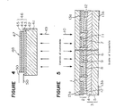
- FIG. 5 shows a typical embodiment of the present invention.
- Said protective layer 3 is composed of a transparent interlayer 4 and a transparent inner glass plate 5, and the inner plate 5 is laminated with the light-transmissive solar cell 2 with the interlayer 4 interposed therebetween.
- At least one of the interlayer 4 and the inner glass plate 5 used as a protective layer is colored. It is preferable that the interlayer 4 is colored and that the visible light-transmittance is from 5 to 60%. If the visible light-transmittance of the colored interlayer is less than 5%, the total visible light-transmittance of the window glass panel is greatly reduced and drivers or passengers can not fully enjoy open-minded feeling.
- the visible light-transmittance of the colored interlayer is higher than 60%, it is difficult to reduce the glare from the back electrode and/or grid electrode of a solar cell.
- the color of the colored transparent interlayer 4 can be optionally selected. For example, bronze, blue, grey or green may be mentioned.
- the material of the interlayer 4 is preferably polyvinyl butyral, ethylene vinyl acetate or urethane, which is commonly used for a laminted glass of an automobile.
- the thickness of the interlayer 4 is preferably from 0.3 to 0.8 mm.
- polyvinyl butyral is preferable, since it has satisfactory penetration-resistance and good adhesive property with glass.
- polyvinyl butyral has a water content of about 0.5% by weight. Therefore the performance of a solar cell is liable to be deteriorated by water freed from polyvinyl butyral when polyvinyl butyral is placed in direct contact with an amorphous silicon photoelectric conversion area.
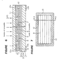
- FIG. 6 is a partially sectional view illustrating an embodiment of the solar cell using a double-layered interlayer composed of two layers 4a and 4b.
- the first interlayer 4a, the second interlayer 4b and an inner glass plate 5, which make a protective layer 3 is colored.
- either interlayer 4a or 4b is colored, and the visible light-transmittance of the colored interlayer is prefereably from 5 to 60%. If the visible light-transmittance of the colored interlayer is less than 5%, drivers and passengers can not fully enjoy open-minded feeling and therefore an object of the present invention can not be achieved.
- the visible light-transmittance of the colored interlayer is higher than 60%, it is difficult to reduce the glare from the back electrode and/or grid electrode of the solar cell.
- the color of the colored transparent interlayer 4a and/or 4b can be optionally selected, including bronze, blue, grey and green.
- the material of the second interlayer 4b is preferably polyvinyl butyral or urethane, which is commonly used for a laminated glass of an automobile, and the thickness of the interlayer 4b is preferably from 0.2 to 0.8 mm.
- the material of the first interlayer 4a in direct contact with a solar cell should preferably have a moisture-permeability coefficient of not higher than 20 (g/hr/cm2/cm).
- a preferable example is ethylene-vinyl acetate (EVA).
- Ethylene-vinyl acetate is pereferable in view of transparency and adhesive property with the back electrode 8 of the solar cell 2.
- Ethylene-vinyl acetate having a thickness of larger than 0.05 mm satisfactorily shields a solar cell from moisture. From the practical view point, the thickness of ethylene-vinyl acetate is preferably from about 0.2 to 0.4 mm, which is easy to handle.
- a thermal ray-absorbing glass prepared by adding a minor amount of a metal oxide or metal such as iron, nickel, cobalt or selenium. It is also favorable to use a thermal ray-refective glass with its surface in contact with the second interlayer being treated.
- the color of the inner glass plate 5 is influenced by the type of metal or metal oxide to be added and the type of surface treatment to be applied, and can be optionally selected, for example, from bronze, blue, grey and green.
- the visible light-transmittance of the transparent inner glass plate 5 should also be preferably from 5 to 60%.
- the transparent protective layer 3 used in the present invention may be composed of one or more plastic layer.
- plastic layer For example, polyethylene terephthalate (PET) having a sufficient durability is preferably used.
- PET polyethylene terephthalate
- a urethane type plastic film having a self-healing properting can also be used.
- the protective layer is composed of a plastic type film only, a window glass panel for an automobile having a light weight and an anti-lacerative property to human body can be provided.
- the light-transmissive solar cell 2 formed on an outer glass plate 1 on the inner side of an automobile in accordance with the present invention is not particularly limited. As shown in Figures 5 and 6, it is generally composed of a light-incident side transparent electrode 6 made of a transparent electroconductive film comprising fluorine-containing tin oxide, tin-containing indium oxide or the like as the main component; a p-, i-, n-type amorphous silicon layer 7 as a photoelectric conversion area; and a transparent back electrode 8 made of a metal oxide, a metal such as Ag, Al and Cr, or a laminted layer of the two.
- a light-incident side transparent electrode 6 made of a transparent electroconductive film comprising fluorine-containing tin oxide, tin-containing indium oxide or the like as the main component
- a p-, i-, n-type amorphous silicon layer 7 as a photoelectric conversion area
- a transparent back electrode 8 made of a metal oxide,
- the thickness of the p-, i-, n-type amorphous silicon layer used for the transparent solar cell-installed window glass panel may be from 2,000 to 5,000 ⁇ .
- Reference numeral 9 in the Figures represents a grid electrode made of e.g. Ag which connects a light-incident side electrode 6 with the corresponding back electrode 8 of the respective solar cell.
- Numeral 12 represents a pair of collective electrodes to take out electromotive force generated in the solar cell.
- an alkali barrier film 11 such as a film comprising silicon dioxide or aluminum oxide as the main component, may be formed between the outer glass plate 11 and the light-incident side electrode 6 in order to protect the light-incident side electrode 6 from being damaged by the alkali component, thereby preventing the electroconductivity of the electrode 6 from lowering.
- the window glass panel of the present invention comprises a light-transmissive solar cell 2 formed on a transparent outer glass plate 1 on the inner side of an automobile and a transparent protective layer 3 formed on the solar cell 2 on the inner side of the automobile, the protective layer 3 being composed of an interlayer 4 and an inner glass plate 5, at least one of which is colored, whereby the glare from the back electrode of the solar cell 2 in the inside of an automobile can be reduced by the colored protective layer.
- the interlayer 4 when the interlayer 4 is composed of two layers, and the interlayer 4a in direct contact with the solar cell 2 is made of ethylene-vinyl acetate having less water content and less moisture permeability, the electric properties of the solar cell 2 is not deteriorated by water, thereby providing a solar cell having a good penetration resistance, the electric properties of which are stable for a long period of time.
- the total visible light-transmittance of the solar cell-installed window glass panel for an automobile using the above-mentioned colored transparent protective layer in accordance with the present invention should be controlled preferably 20% or less, thereby removing the glare as viewed from the inside of the automobile.
- the open-minded feeling in the inside of the automobile can be assured if the visible light-transmittance is at least a few percents, e.g. 5% or more.
- a window glass panel comprising a solar cell 2 having a collective electrode 12 along the peripheral margin formed on a transparent outer glass plate 1 and a transparent protective layer 3 formed on the solar cell 2, the collective electrode 12 is visible from both the inside and the outside of the automobile. It is therefore preferable for beautiful external appearance to conceal the colllective electrode.
- Figures 5 and 6 illustrate the cross sections taken along the line A-A in Figure 7.
- the light-shielding colored layer 13 is not particularly limited, but it is generally a ceramic color ink, as shown in Figure 1c and Figure 2, which comprises a pigment to give a desired color, a low melting glass frit to form a paint film intimately adhered with the glass sheet, various refractor fillers and oil for screen-printing. It is preferable that the ceramic color ink does not deteriorate during forming an alkali barrier coating 11 or a light-incident side electrode 6 thereon. Further, it should not adversely affect the upper layer to be formed in contact therewith.
- Figrues 5 and 6 illustrate embodiments wherein light-shielding colored layers 13a and 13b are formed on an outer glass plate 1 on the inside of an automobile and on an inner glass plate 5 on the inside of an automobile, respectively, but they may be formed on the outer glass plate 1 and on the inner glass plate 5 both on the outside of the automobile. However, it is generally preferred to form the light-shielding colored layer 13a on the outer glass plate 1 along the peripheral margin not on the outside of an automobile but on the inside of an automobile as shown in Figures 5 and 6 in view of weather-resistance and external appearance.
- a light-shielding colored layer may be formed on either the inside or the outside of an automobile.
- Figures 5 and 6 illustrate the cases wherein the light-shielding colored layer 13b is formed on the inner glass plate 5 along the peripheral margin on the inside of an automobile.
- the glass substrate having a curved surface shape for the solar cell is prepared by firstly forming a light-shielding colored layer 13a on a flat outer glass plate along the peripheral margin, forming thereon a light-incident side electrode 6, a collective electrode 12 and a grid electrode 9, placing the resultant outer glass plate in such as manner as to make the light-incident side electrode 6, etc.
- the light-shielding colored layer 13b is formed on the inner glass plate on the inside of an automboile when the bending step is carried out by the above-mentioned method.
- a light-shielding colored layer may be formed on the inner glass plate on either the inside or the outside of an automobile.
- a light-shielding colored layer is required to be formed in a large thickness, it is preferable to form the light-shielding colored layer on the inner glass plate on the inside of an automobile. Otherwise, the outer glass plate having the thick light-shielding colored layer formed on the inside of an automobile and the inner glass plate having the thick light-shielding colored layer formed on the outside of the automobile are not satisfactorily laminated with an interlayer 4 located therebetween.
- the light-shielding colored layer 13 has another merit of concealing a dirty part produced when an interlayer constituting a window glass panel is deteriorated along the peripheral margin by reaction with water, thereby spoiling external appearance.
- a method for producing a glass substrate having such a curved surface suitable for a solar cell-installed window glass panel comrises firstly washing a flat outer glass plate 1; forming a light-shielding colored layer 13, for example ceramic color ink, on the washed outer glass plate along the peripheral margin by printing and baking; forming an alkali barrier coating 11 and a light-incident side electrode 6 thereon; forming a grid electrode 9 and a collective electrode 12 made of e.g.
- the final bending treatment is effected preferably by a self-weight bending method so as not to deteriorate the light-incident side electrode 6, etc, after placing the inner glass plate on the light-incident side electrode 6, etc. of the outer glass plate.
- the inner glass plate is separated from the outer glass plate, and a photoelectric conversion layer 7 and a back electrode 8 are formed on the light-incident side electrode on the outer glass plate.
- the outer glass plate thus treated is then laminated with the inner glass plate preferably by interposing an interlayer 4 therebetween.
- a solar cell-installed window glass panel laminated by interposing an interlayer therebetween as shown in Figures 2, 5 and 6 is preferably sealed along its peripheral margin in order to protect the peripheral margin from being damaged by water, therevy preventing the lowering of the performance of the solar cell and also preventing Ag in the grid electrode 9 and the collective electrode 12 from whitening.
- Figure 8 is a cross sectional view illustrating an embodiment of sealing the peripheral margin of the solar cell-installed window glass panel as shown in Figure 5.
- a sealing material 14 to seal the peripheral margin should preferably have a moisture-permeability coefficient of less than 20 (g/hr/cm2/cm) in order to achieve satisfactory sealing effect.
- the shape of the sealing material is not particularly limited, but the sealing material may have a shape suitable for fixing a solar cell-installed window glass panel into an automobile body and it may work not only for sealing but also as a mole.
- the damage by water at the peripheral margin of the glass panel can be prevented by sealing the peripheral margin with a sealing material having a less moisture-permeability coefficient, thereby preventing the lowering of the performance of a solar cell caused by reaction of water with the a-Si layer 7 constituting the photoelectric convertion area of a solar cell, with the grid electrode 9, or with the collective electrode 12, and also preventing the whitening of Ag which is the main component of the grid electrode 9 or collective electrode 12.
- a synthetic resin can be molded into a desired shape along the peripheral margin of a solar cell-installed window glass panel of the present invention by an extrusion molding, injection molding, transfer molding, RIM (reaction injection molding) or LIM (liquid injection molding) method, so that the window glass panel can be easily fixed into an automobile body 16, and in such a case a decorative mole and a gasket 15 can be integrally molded.
- the type of the synthetic resin used for this purpose is not particularly limited if it is molded and solidified by the above-mentioned various molding methods. However, it is preferable for productivity and manufacturing cost to mold a mole or gasket made of polyurethane by RIM method from a polyol and an isocyanate compound or to mold a mole or gasket from a vinyl chloride type resin by injection molding method.
- thermoplastic resins or thermoplastic rubbers such as an ethylene-vinyl acetate copolymer (EVA), butyl rubber or polyvinyl chloride, thermosetting resins such as epoxy resin, and fluorine resin, may also be used.
- EVA ethylene-vinyl acetate copolymer
- thermosetting resins such as epoxy resin, and fluorine resin
- the mole or gasket 15 is molded preferably so as to cover the sealing material 14 sealing the peripheral margin.
- a synthetic resin having a sufficiently small moisture-permeability coefficient such as EVA, butyl rubber, fluorine resin or epoxy resin
- the mole or gasket may be molded directly along the peripheral margin of a solar cell-installed window glass panel so as to serve also as the sealing material 14.
- a gasket is regarded as intended for sealing a window glass panel fixed to an automobile body, and a mole is regarded as intended for decoration.
- the gasket and mole are not particulrly discriminated and used in substantially the same meaning.
- a gasket 15 made of a resin should preferably have such a shape as to be easily mounted on an automobile body 16.
- the gasket 15 may be integrally molded, together with a mounting element to the automobile body 16, for example, with a part of a retainer embedded in the gasket.
- a lead wire 17 to take out electric power from a pair of collective electrodes 12 may also be integrally embedded, thereby providing a good external appearance and protecting the contact point between the collective electrode 12 and the lead wire 17 from being attacked by water, chemicals, etc. In this manner, the collection of electric power can be effected without being adversely affected by external physical factors including tensile force, impact force or the like.
- a terminal 18 and a lead wire 17 for taking out electric power from a solar cell may also be integrally embedded by molding.
- external circuits 19 to support a solar cell including a diode for preventing reverse current, a circuit for stabilizing electric voltage, a circuit for stabilizing electric current and other circuits necessary for an automobile, may also be embedded by molding. In this manner, these external circuits can be placed without spoiling the external appearance, and can be stabilized for a long period of time, thus being protected from external impact force, water chemicals and the like.
- Figure 9d illustrates still another preferable embodiment of the present invention.
- a gasket material is integrally molded into a cavity space along the peripheral margin of a window glass panel by RIM method, injection molding method or the like, it is sometimes difficult to fix flexible elements such as a lead wire or the like into a desired place.
- a metallic element having a fixed shape to take out electric power from a solar cell.
- Figure 9d illustrates an embodiment wherein a fixed terminal 18 electrically connected with a light-incident side electrode 6 is provided in place of the flexible lead wire, so that it protrudes out from a gasket 15 and a lead wire may be electrically connected to the protruded portion of the fixed terminal 18.
- circuits including a circuit for preventing reverse current are embedded as shown in Figure 9c
- the circuits may be preferably connected with the fixed terminal to take out electric power.
- a soda lime silicate glass sheet of 870 x 285 x 2 (mm) was thoroughly washed, dried and thereafter placed in a CVD furnace of belt conveyor conveying type.
- SiH4 gas and O2 gas were then introduced into the CVD furnace, in an SiH4:02 ratio of about 1:10, and a silicon oxide film (700 ⁇ ) was formed by CVD method at a glass sheet surface temperature of about 450°C as an alkali barrier coating.
- the conveying speed of the glass sheet in the alkali barrier coating and tin oxide film coating zone was 0.60 m/min.
- the resultant transparent electroconductive film-coated glass sheet (hereinafter referred to as "TCO substrate") had a surface resistance of 8.0 ⁇ / ⁇ .
- the TCO substrate thus obtained was placed on a frame having a desired curved surface shape for self-weight bending by gravity bending method, so that the tin oxide film is located above, and the substrate was heated to 590°C.
- the self-weight bending was then effected to make the tin oxide side surface concave.
- Table 1 Various properties of the TCO substrate having the curved surface shape thus obtained are shown in Table 1.
- the transmittance *1 was measured by an integrating-sphere photometer using C Light Source (JIS Z8720) as a light source. Bending A *2 shows the maximum displacement of the longer edge, and Bending B *2 shows the maximum displacement of the shorter edge.
- C Light Source JIS Z8720
- a soda lime silicate glass sheet of 1013 x 445 x 3 (mm) was thoroughly washed, and placed in the same CVD furnace as used in Example 1.
- a silicon oxide film (700 ⁇ ) and a transparent electroconctive film (7,000 ⁇ ) of tin oxide containing 1.0% by weight of fluorine were then formed on the glass sheet by the CVD method in the same manner as in Example 1, except that the conveying speed of the glass sheet was changed to 0.45 m/min.
- the TCO substrate thus obtained had a surface resistance of 6.0 ⁇ / ⁇ .
- the TCO substrate was then suspended by a suspender, and heated to 630°C.
- the heated TCO substrate was then press-bended to make the tin oxide side surface concave, and the press-bended TCO substrate was subjected to a strengthening treatment by air cooling.
- Various properties of the TCO substrate having the curved surface shape thus obtained are shown in Table 1.
- the TCO substrate having the desired curved surface was obtained, with its physical properties substantially unchanged before and after bending.
- the TCO substrate had a surface compressive stress of 400 kgf/cm2.
- Example 1 Example 2 Before bending Surface resistance ( ⁇ / ⁇ ) 8.0 6.0 Transmittance *1 (%) 80 79 After bending Surface resistance ( ⁇ / ⁇ ) 8.1 6.3 Transmittance *1 (%) 80 79 Bending A *2 (mm) 19 31 Bending B *2 (mm) 5 8.5 External appearance No change No change *1: The transmittance was measured by an integrating-sphere photometor using C Light Source (JIS Z8720). *2: The Bending A shows the maximum displacement of the longer edge, and the Bnding B shows the maximum displacement of the shorter edge.
- the optical properties of the window glass panel are shown in Table 2 together with those of Comaravtive Example 1.
- the optical properties of the window glass panel are shown in Table 2, together with those of Comparative Example 1.
- the initial value of the maximum output power (Pmax) of the solar cell embedded in this sunroof is defined as 1, and the lowering of the maximum output power with the passage of time when exposed to the atmosphere is expressed by Line A in Figure 10.
- the optical properties of this comparavtive window glass panel are shown in Table 2.
- the initial value of the maximum output power (Pmax) of the solar cell embedded in this comparative sunroof is defined as 1, and the lowering of the maximum output power with the passage of time when exposed to the atmosphere is expressed by Line B in Figure 10.
- Example 3 Comparative Example 1 Visible light-transmittance (%) 4.2 3.7 6.7 Reflectance in the inside of automobile (%) 5.7 5.9 23.4 Glare in the inside of automobile Nil Nil Much Concealment of grid electrode Good Good No good
- the output power of a solar cell is more stable for a long period of time when ethylene-vinyl acetate having a less water content and a smaller moisture-permeability as the first interlayer in contact with the solar cell 2 (Example 4, Line A) is used in comparison with when polyvinyl butyral (Comparative Example 1, Line B) is used.
- the window glass panel was sealed along the entire peripheral margin with butyl rubber having a moisture-permeability of from 0.1 to 0.5 (g/hr/cm2/cm).
- a window glass panel for a sunroof was prepard in the same manner as in Example 5, except that Thiokol having a moisture-permeability of 80 (g/hr/cm2/cm) was used as a sealing material.
- a window glass panel for a sunroof was prepared in the same manner as in Example 5, except that silicone having a moisture-permeability of 350 (g/hr/cm2/cm) was used as a sealing material.
- the window glass panel sealed with Thiokal having a moisture-permeability of 8.0 provided substantially the same results in the temperature-moisture cycle test as Example 5, but provided poorer durability in the exposure test as compared with Example 5.
- a solar cell-installed window glass panel for a sunroof was prepared in the same manner as in Example 6, except that neither a sealing material 14 nor a gasket 15 was formed.
- a solar cell-installed window glass panel for a sunroof was prepared in the same manner as in Example 7, except that the sealing material 14 was omitted.
Landscapes
- Chemical & Material Sciences (AREA)
- Engineering & Computer Science (AREA)
- Materials Engineering (AREA)
- Life Sciences & Earth Sciences (AREA)
- Chemical Kinetics & Catalysis (AREA)
- General Chemical & Material Sciences (AREA)
- Geochemistry & Mineralogy (AREA)
- Organic Chemistry (AREA)
- Mechanical Engineering (AREA)
- Thermal Sciences (AREA)
- Physics & Mathematics (AREA)
- Photovoltaic Devices (AREA)
- Surface Treatment Of Glass (AREA)
Abstract
Description
- This invention relates to a glass substrate for a solar cell having a curved surface suitable for a window glass panel for an automobile, a method for producing the same, and a solar cell. Particularly, it relates to a solar cell-installed window glass panel for an automobile. More particularly, it relates to such window glass panel for an automobile transparent to visible light, particularly suitable as a sunroof, opera window or the like for an automobile.
- A solar cell is regarded as a prospective photoelectric conversion apparatus which is capable of cleanly producing electric power without causing environmental pollution by using sunlight as an inexhaustible energy source unlike other energy sources such as petroleum, coal or nautral gas.
- Among such solar cells, a solar cell using amorphous silicon (a-Si) as a semi-conductor layer for effecting photoelectric conversion is widely used since it can be produced at a relatively low cost and it assures a relatively satisfactory photoelectric conversion efficiency. As a typical example of such an amorphous silicon (a-Si) solar cell, Figure 4 illustrates an a-Si
solar cell 48 having an a-Sisemiconductor layer 46 composed of p-type a-Silayer 43, i-type a-Silayer 44 and n-type a-Silayer 45 and analuminum electrode 47 laminated sequentially on a transparentelectroconductive film 42 formed on atransparent insulating sheet 41. In the a-Sisolar cell 48, light 49 incident on thetransparent insulating sheet 41 is absorbed in the a-Silayer 46 thereby generating an electromotive force between the transparentelectroconductive film 42 and thealuminum electrode 47, and the electric power thus generated is taken out throughlead wires 50. - Small size types of such a-Si solar cells are already used as cells for table computers, watches and the like. In future, such cells are expected to be used for power generation, automobiles, ships, and the like by improving their photoelectric conversion, enlarging their sizes, and lowering their manufacturing costs. particularly, a solar cell for an automobile is expected to be loaded on an automobile for use as an electric power supply to drive a ventilator during parking or other electronic equipments in the inside of the automobile.
- It is expected that a solar cell is used in the above-mentioned fields. For a practical application, however, a solar cell having a curved surface is desired depending on its particular purpose. For exampe, an automobile body is desired to have a curved shape in view of aerodynamic aptitude and design, and acocrdingly a solar cell loaded thereon is also required to have a curved surface fitted thereto.
- Heretofore, it is known to use a bilayer glass having a solar cell of a flat plate-like small silicon wafer embedded between two glass plates, as a sunroof and the like. However, there has been a restriction such that the silicon wafer itself can not be subjected to a bending treatment, and it must be used in the state of a flat plate. It is also inferior from the viewpoint of manufacturing costs and productivity. From the viewpoint of the design, productivity and the like, it is desired that a solar cell itself has a curved surface shape.
- It is conceivable to use a flexible plastic film as the transparent insulating sheet in order to make a curve-shaped solar cell, but the plastic film is generally inferior in weather-resistance. Furthermore, when it is used for an automobile in the state of being exposed to atmosphere, it is weak in impact-resistance, scratch-resistance and the like. It is also undurable to high temperature at which an a-Si semiconductor film of a solar cel is formed. Thus, a plastic film has been generally unsuitable as the transparent insulating sheet for a solar cell.
- As mentioned above, there have been attempts to use a solar cell as an electric power source for driving an air ventilator during parking or other electronic equipments of an automobile. For example, Japanese Unexamined Patent Publication No. 115719/1986 discloses a sunroof for an automobile having a solar cell mounted thereon. However, the solar cell used therein is not visible light-transmissive, but rather it is intended to impart a light-shielding property to the sunroof by using a light-shielding solar cell. Japanese Unexamined Patent Publication no. 199466/1988 discloses a light-transmissive solar cell, but there is no provision for a protective layer.
- On the other hand, an automobile having a glass plate panelled on a sunroof window is popular as the glass-panelled sunroof gives open-minded feeling to drivers and passengers. Accordingly, a solar cell loaded on the automobile and a protective layer therefor are required to be visible light-transmissive for this purpose. However, if the protective layer is light-transmissive, a grid electrode, a collective busbar and the like of the solar cell are visible from the inside of the automobile, thus spoiling the appearance. Moreover, there has been a problem that when a highly reflective metal such as Ag, Al, Cr and the like is used as a back electrode of the solar cell, drivers and passengers are dazzled by the glare from the highly reflective metal goods and their eyes are sometimes fatigued.
- An object of the present invention is to provide a glass substrate for a solar cell having a curved surface shape, which is free from the above-mentioned problems, and to provide a solar cell-installed window glass panel, particularly a sunroof, for an automobile, having an excellent appearance and visible light-transmittance.
- The present invention provides a glass substrate for a solar cell, comprising a glass sheet having a curved surface shape and a transparent electroconductive film formed on the concave surface side of said glass sheet.
- The present invention also provides a method for producing a glass substrate for a solar cell having a curved surface shape, which comprises heating a glass sheet, forming a transparent electroconductive film on said glass sheet and then subjecting the resultant glass substrate to a bending treatment in such a manner as to make the transparent electroconductive film surface of the glass substrate in the shape of a concave surface.
- Further, the present invention provides a solar cell-installed window glass panel for an automobile, comprising a transparent outer glass plate having a light-transmitting solar cell using amorphous silicon as a photoelectric conversion layer formed on the inner side of an automobile, and a transparent protective layer formed to cover said amorphous silicon solar cell on the inner side of the automobile.
- Now, the present invention will be described in detail with reference to the preferred embodiments.
- In the accompanying drawings:
- Figures 1a to 1c are cross-sectional views illustrating different embodiemnts of the glass substrate for a solar cell having a curved surface shape in accordance with the present invention.
- Figure 2 is a cross-sectional view illustrating an outline of a solar cell for a sunroof having a curved surface shape, wherein the glass substrate of the present invention is employed.
- Figure 3 shows a graph illustrating the rising rate of resistance in relation to the heating temperature and time with regard to a glass substrate having a transparent electroconductive film.
- Figure 4 is a cross-sectional view illustrating a conventional amorphous silicon solar cell.
- Figure 5 is a cross-sectional view illustrating an embodiment of the solar cell-installed window glass panel for an automobile in accordance with the present invention.
- Figure 6 is a cross-sectional view illustrating another embodiment of the solar cell-installed window glass panel for an automobile in accordance with the present invention.
- Figure 7 is a plain outline view of an embodiment of the solar cell-installed window glass panel for an automobile in accordance with the present invention, as viewed from the outside or the inside of the automobile.
- Figure 8 is a cross-sectional view illustrating an embodiment of the solar cell-installed window glass panel for an automobile, sealed along the peripheral margin, in accordance with the present invention.
- Figures 9a to 9d are cross-sectional views illustrating different embodiments of the solar cell-installed window glass panel having a gasket integrally molded along the peripheral margin, thereby being fixed to an automobile body, in accordance with the present invention.
- Figure 10 shows a graph illustrating the deterioration tendency with the passage of time of the power output of the solar cells embedded in the sunroofs of Example 4 and Comparative Example 1 after being naturally exposed to atmosphere.
- Figure 11 is a diagram illustrating a temperature-humidity cycle test applied to the sunroofs prepared in accordance with Example 5, Comparative Examples 2 and 3.
- Figure 12 shows a graph illustrating the deterioration in the power output of the solar cells embedded in the sunroofs of Example 5,
Comparative Exmples - Figure 13 shows a graph illustrating the deterioration in the power output of the solar cells embedded in the sunroofs of Example 5, Comparative Examples 2 and 3 after being naturally exposed to atmosphere.
- Figures 1a to 1c are cross-sectional views illustrating various embodiments of the glass substrate for a solar cell having the curved surface shape in accordance with the present invention.
- The
glass sheet 1 used in the present invention is an insulating transparent sheet having a high light-transmittance, for example a transmittance of at least 85%, in the wavelength range of 350 - 800 nm, and having a high chemical and physical durability and good optical properties. For example, soda-lime silicate glass, aluminosilicate glass, borosilicate glass, lithium aluminosilicate glass, or various other types of glass may be employed. - The thickness of the the
glass sheet 1 is not particularly limited, but is suitably from 1.0 to 5.0 mm when various factors such as the easiness of bending treatment, light transmittance, weight, strength, the convenience of handling, and the like are taken into consideration. - The curvature of a glass substrate for a solar cell having a curved surface shape of the present invention is not particularly limited, but if the glass substrate having a transaparent electroconductive film is bended into a too small radius of curvature, it sometimes causes such strain as to deteriorate the transparent electrocondctive film, and it is difficult to uniformly form an a-Si film on the curved surface. Thus, a suitable radius of curvature (R) is not less than 80 mm, preferably not less than 500 mm.
- Examples of a transparent
electroconductive film 2 formed on aglass sheet 1 include highly electroconductive transparent metallic oxides such as tin oxide doped with fluorine in an amount of from 0.1 to 5% by weight, tin oxide doped with antimony in an amount of from 0.1 to 30% by weight, indium oxide doped with tin in an amount of from 0.5 to 30% by weight, and the like. Among them, a transparent electroconductive film comprising tin oxide doped with fluorine is most suitable as the transparent elctroconductive film for a solar cell since it easily provides a low sheet resistance of not higher than 10 Ω/□, and it has a high durability to a highly reductive hydrogen plasma used for the formation of a-Si by plasma CVD method. The thickness of the transparent electroconductive film is suitably from 300 to 10,000 Å. - The transparent electroconductive film used in the present invention can be formed by various conventional methods such as CVD method, spraying method, sputtering method, vacuum depositing method, ion plating method, dipping method and the like. Among them, CVD method and sputtering method are most suitable since they produce a satisfactory uniform electroconductive film of low resistance.
- As seen from Figures 1a to 1c, the glass substrate for a solar cell having a curved surface of the present invention comprises a
glass sheet 1 having a curved surface shaped and a transparentelectroconductive film 2 formed on the concave surface side of theglass sheet 1. If a flat plate-like glass substrate having a transparent electroconductive film formed thereon is heated to a bending treatment temperture and the heated substrate is bended in such a manner as to make the transparent electrocondctive film surface concave, the transparent electroconductive film is liable to remarkable deterioration as it cracks and/or peels off from the glass sheet. Furthermore, in many practical cases, a solar cell is prepared by forming a photoelectric conversion layer on the concave surface of a glass substrate. Thus, it is preferable also for practical use to form a transparent electroconductive film on the concave surface side of a glass sheet. For example, as seen from Figure 2, the desired solar cell for a sunroof of an automobile comprises aglass sheet 21, the convex side of which is exposed to atmosphere, atransperent electroconductive film 22 formed on the concave side of theglass sheet 21, i.e. on the inner side of the automobile, ana-Si semiconductor layer 25 formed on thetransparent electroconductive film 22, and aback electrode 26 formed on thea-Si semiconductor layer 25. - When the
glass sheet 1 comprises an alkali metal-containing glass such as soda lime silicate glass or the like, as shwon in Figures 1b and 1c, analkali barrier coating 11 may be optionally applied on theglass sheet 1 in order to prevent thetransparent electroconductive film 6 from being adversely affected by alkali eluted from the surface of theglass sheet 1. Examples of thealkali barrier coating 11 include silicon oxide film, aluminum oxide film and zirconium oxide film, and the thickness of the alkali barrier coating is suitably from 500 to 800 Å. - As seen from Figure 1c, a light-shielding
colored layer 13 may be formed beneath thetransparent electroconductive film 6 and thealkali barrier coating 11, along the peripheral margin of the glass substrate for a solar cell having a curved surface shape of the present invention in order to shield a collective busbar usually formed along the peripheral margin so that the busbar can be concealed from one's eyes, thus improving external appearance. The light-shieldingcolored layer 13 is not particularly limited, but it is generally a ceramic color ink comprising a pigment to generate a desired color, a low melting glass frit to form a paint film intimately adhered with the glass sheet, various refractory fillers, oil for screen-printing, and the like. It is preferable that the ceramic color ink does not deteriorate during forming thealkali barrier coating 11 or thetransparent electoconductive film 6 thereon, and that it does not adversely affect the upper layer formed in contact therewith. - A suitable method for preparing a glass substrate for a solar cell having a curved surface shape as shown in Figure 1c, comprises screen-printing a
ceramic color ink 13 on aglass sheet 1 along the peripheral margin, drying the printedglass sheet 1, forming analkali barrier coating 11 on the driedglass sheet 1 in the alkali barrier coating zone of a CVD furnace, forming atransparent electroconductive film 6 on the alkali barrier coating in the transparent electroconductive film forming zone of the CVD furnace, and finally subjecting the glass substrate thus prepared to a bending treatment. - In the present invention, the glass substrate for a solar cell having a transprent electroconductive film is subjected to a bending treatment. Example of a bending method used for this treatment generally include a press-bending method which comprises press-bending a glass substrate heated to a bending temperature by a press mold (e.g. the bending temperature of soda lime silicate glass is from 570 to 700°C); a gravity-bending method using the self-weight of a glass substrate in bending; an air forming method which comprises having a glass substrate adsorbed and bended by an adsorbing mold; and a blow-bending method by a gas blow.
- The glass substrate thus bended may be subjected to a strengthening treatment. The strengthening treatment can be effected by blowing a quenching air to the bended glass substrate in the quenching step after the bending treatment, thereby quench-strengthening the bended glass substrate. Another way of strengthening the bended glass sheet is a chemical strengthening method by ion exchange.
- In the preparation of the glass substrate for a solar cell in accordance with the present invention, the bending treatment may be carried out any time before or after forming the transparent electroconductive film on a glass sheet. However, when it is difficult to uniformly form the transparent electroconductive film on the bended glass sheet (for example when the film formation is effected by CVD method), it is preferable to carry out the bending treatment after forming the transparent electroconductive film on a flat plate-like glass sheet. Also, when it is necessary for the formation of a transparent electroconductive film to heat the glass sheet to such a high temperature as to substantially deform the glass sheet (for example when the film is formed by CVD method), it is preferable to effect the bending treatment after the formation of the film. Because the accuracy of the bending deteriorates and the desired curved surface shape can not be obtained if the bended glass sheet is heated to a high temperature for the formation of the film.
- A great care must be taken to heat the glass substrate for bending after the formation of the transparent electroconductive film. If the glass substrate is heated to an excessively high temperature, the transparent electroconductive film is likely to be impaired by the thermal expansion difference with glass, oxidation, or other factors, thereby resulting in the rise of resistance value and the degradation of light-transmittance.
- We have carried out an experiment to determine preferable conditions for bending the glass substrate having a transparent electroconductive film, and obtained the results as shown in Figure 3. That is,
Figue 3 is a graph showing a relation between the rising rate of resistance value Rs/Ro (Ro shows the resistance values of the transparent electroconductive film before heating, and Rs shows those after heating) and the heating temperature and heating time when a glass substrate having a fluorine-doped tin oxide film is heated in a heating furnace in the atmosphere of air. As can be seen from these results, if the heating temperature is set not higher than 650°C and the heating time is set not longer than 2 minutes, the rise of resistance value of the transparent electroconductive film can be controlled to a minimum. Thus, these heating conditions are most preferable for bending the glass substrate having the transparent electroconductive film of the present invention. - That is, the most suitable method for producing a bending-treated glass substrate for a solar cell comprises heating a glass sheet at from 500 to 600°C, coating a transparent electroconductive film on one side of the glass sheet by CVD method, and bending the formed glass substrate at a bending temperature of from 580 to 650°C. According to this method, a glass substrate having stable performance can be produced at a high mass-productivity and at a low cost. Furthermore, when a strengthening treatment step is added to this method, a glass substrate produced thereby is durable to external impacts when exposed to the outside atmosphere, and is not damaged by hails, small stones, and the like. This strengthening treatment can be effected by a quench-strengthening method which comprises blowing cooling air at the cooling step after the bending treatment, or other methods including a chemical strengthening method using ion-exchange.
- The solar cell having a curved surface shape using the glass substrate of the present invention is suitable for use where a good design is required, and is particularly suitable for bending mounted in a sunroof of an automobile.
- Figure 2 shows an embodiment of the solar cell using the glass substrate of the present invention to be mounted in a sunroof of an automobile. That is, the solar cell shown in Figure 2 comprises a curve-shaped
glass sheet 21 having a ceramiccolor ink layer 24 on the concave surface along the peripheral margin, an alkali-barrier coating 23 formed thereon, atransparent electroconductive film 22, an amorphous siliconphotoelectric conversion layer 25, and aback electrode 26 formed thereon. The solar cell is then laminated with aglass plate 28 having substantially the same curved surfce as that of theglass sheet 21 with aninterlayer 27 interposed therebetween.Light 29 incident on theglass sheet 21 of the solar cell thus prepared is absorbed in thea-Si layer 25, thereby generating an electromotive force between thetransparent electroconductive film 23 and theback electrode 26, and the electromotive force thus generated is taken out by lead wire or other means (not shown in Figure 2). - As mentioned above, the present invention provides a glass substrate having a transparent electroconductive film suitable for a solar cell having a curved surface shape, which is superior in weather-resistance and crack-resistance to a solar cell using a plastic film as a substrate, and it is thereby possible to produce solar cells of various curved surface shapes.
- According to the method for producing a glass substrate of the present inveniton, a curve-shape glass substrate having a transparent electroconductive film of good quality can be produced at a low cost by forming the transparent electroconductive film on a glass sheet and then subjecting the resultant glass substrate to a bending treatment without substantially deteriorating the transparent electroconductive film.
- The solar cell for a sunroof of the present inveniton has many advantages of having a good aerodynamic aptitude for an automobile body, efficiently utilizing light incident on the sunroof, and also having a good design.
- Another preferable embodiment of the present invention is explained hereinafter in accordance with the attached drawings. A solar cell-installed window glass panel of the present invention comprises an
outer glass plate 1, a light-transmissivesolar cell 2 formed on theouter glass plate 1 on the inner side of an automobile, and a transparentprotective layer 3 formed on thesolar cell 2 on the inner side of an automobile. Theprotective layer 3 is made of a material having a penetration resistance, which controls the transmission of visible light. - Figure 5 shows a typical embodiment of the present invention. Said
protective layer 3 is composed of atransparent interlayer 4 and a transparentinner glass plate 5, and theinner plate 5 is laminated with the light-transmissivesolar cell 2 with theinterlayer 4 interposed therebetween. At least one of theinterlayer 4 and theinner glass plate 5 used as a protective layer is colored. It is preferable that theinterlayer 4 is colored and that the visible light-transmittance is from 5 to 60%. If the visible light-transmittance of the colored interlayer is less than 5%, the total visible light-transmittance of the window glass panel is greatly reduced and drivers or passengers can not fully enjoy open-minded feeling. On the other hand, if the visible light-transmittance of the colored interlayer is higher than 60%, it is difficult to reduce the glare from the back electrode and/or grid electrode of a solar cell. The color of the coloredtransparent interlayer 4 can be optionally selected. For example, bronze, blue, grey or green may be mentioned. The material of theinterlayer 4 is preferably polyvinyl butyral, ethylene vinyl acetate or urethane, which is commonly used for a laminted glass of an automobile. The thickness of theinterlayer 4 is preferably from 0.3 to 0.8 mm. - Among them, polyvinyl butyral is preferable, since it has satisfactory penetration-resistance and good adhesive property with glass. However, polyvinyl butyral has a water content of about 0.5% by weight. Therefore the performance of a solar cell is liable to be deteriorated by water freed from polyvinyl butyral when polyvinyl butyral is placed in direct contact with an amorphous silicon photoelectric conversion area.
- On the other hand, the water content of ethylene-vinyl acetate is adequately low, but the penetration-resistance is a little poor as compared with that of polyvinyl butyral.
- Accordingly, a double-layered interlayer prepared by laminating the two materials has both advantages of the two. Figure 6 is a partially sectional view illustrating an embodiment of the solar cell using a double-layered interlayer composed of two layers 4a and 4b. In this embodiment, at least one of the first interlayer 4a, the second interlayer 4b and an
inner glass plate 5, which make aprotective layer 3, is colored. Preferably, either interlayer 4a or 4b is colored, and the visible light-transmittance of the colored interlayer is prefereably from 5 to 60%. If the visible light-transmittance of the colored interlayer is less than 5%, drivers and passengers can not fully enjoy open-minded feeling and therefore an object of the present invention can not be achieved. On the other hand, if the visible light-transmittance of the colored interlayer is higher than 60%, it is difficult to reduce the glare from the back electrode and/or grid electrode of the solar cell. The color of the colored transparent interlayer 4a and/or 4b can be optionally selected, including bronze, blue, grey and green. - The material of the second interlayer 4b is preferably polyvinyl butyral or urethane, which is commonly used for a laminated glass of an automobile, and the thickness of the interlayer 4b is preferably from 0.2 to 0.8 mm.
- On the other hand, the material of the first interlayer 4a in direct contact with a solar cell should preferably have a moisture-permeability coefficient of not higher than 20 (g/hr/cm²/cm). A preferable example is ethylene-vinyl acetate (EVA). Ethylene-vinyl acetate is pereferable in view of transparency and adhesive property with the
back electrode 8 of thesolar cell 2. Ethylene-vinyl acetate having a thickness of larger than 0.05 mm satisfactorily shields a solar cell from moisture. From the practical view point, the thickness of ethylene-vinyl acetate is preferably from about 0.2 to 0.4 mm, which is easy to handle. - In the embodiments as shown in Figures 5 and 6, when a colored transparent
inner glass plate 5 is used, it is favorable to use a thermal ray-absorbing glass prepared by adding a minor amount of a metal oxide or metal such as iron, nickel, cobalt or selenium. It is also favorable to use a thermal ray-refective glass with its surface in contact with the second interlayer being treated. The color of theinner glass plate 5 is influenced by the type of metal or metal oxide to be added and the type of surface treatment to be applied, and can be optionally selected, for example, from bronze, blue, grey and green. The visible light-transmittance of the transparentinner glass plate 5 should also be preferably from 5 to 60%. - The transparent
protective layer 3 used in the present invention may be composed of one or more plastic layer. For example, polyethylene terephthalate (PET) having a sufficient durability is preferably used. Furthermore, a urethane type plastic film having a self-healing properting can also be used. When the protective layer is composed of a plastic type film only, a window glass panel for an automobile having a light weight and an anti-lacerative property to human body can be provided. - The light-transmissive
solar cell 2 formed on anouter glass plate 1 on the inner side of an automobile in accordance with the present invention is not particularly limited. As shown in Figures 5 and 6, it is generally composed of a light-incident sidetransparent electrode 6 made of a transparent electroconductive film comprising fluorine-containing tin oxide, tin-containing indium oxide or the like as the main component; a p-, i-, n-typeamorphous silicon layer 7 as a photoelectric conversion area; and atransparent back electrode 8 made of a metal oxide, a metal such as Ag, Al and Cr, or a laminted layer of the two. The thickness of the p-, i-, n-type amorphous silicon layer used for the transparent solar cell-installed window glass panel may be from 2,000 to 5,000 Å.Reference numeral 9 in the Figures represents a grid electrode made of e.g. Ag which connects a light-incident side electrode 6 with thecorresponding back electrode 8 of the respective solar cell.Numeral 12 represents a pair of collective electrodes to take out electromotive force generated in the solar cell. When an alkali metal-containing glass is used as theouter glass plate 1, analkali barrier film 11 such as a film comprising silicon dioxide or aluminum oxide as the main component, may be formed between theouter glass plate 11 and the light-incident side electrode 6 in order to protect the light-incident side electrode 6 from being damaged by the alkali component, thereby preventing the electroconductivity of theelectrode 6 from lowering. - The window glass panel of the present invention comprises a light-transmissive
solar cell 2 formed on a transparentouter glass plate 1 on the inner side of an automobile and a transparentprotective layer 3 formed on thesolar cell 2 on the inner side of the automobile, theprotective layer 3 being composed of aninterlayer 4 and aninner glass plate 5, at least one of which is colored, whereby the glare from the back electrode of thesolar cell 2 in the inside of an automobile can be reduced by the colored protective layer. - Furthermore, as shown in
Figue 6, when theinterlayer 4 is composed of two layers, and the interlayer 4a in direct contact with thesolar cell 2 is made of ethylene-vinyl acetate having less water content and less moisture permeability, the electric properties of thesolar cell 2 is not deteriorated by water, thereby providing a solar cell having a good penetration resistance, the electric properties of which are stable for a long period of time. - The total visible light-transmittance of the solar cell-installed window glass panel for an automobile using the above-mentioned colored transparent protective layer in accordance with the present invention should be controlled preferably 20% or less, thereby removing the glare as viewed from the inside of the automobile. The open-minded feeling in the inside of the automobile can be assured if the visible light-transmittance is at least a few percents, e.g. 5% or more.
- As shown in Figures 5 and 6, in a window glass panel comprising a
solar cell 2 having acollective electrode 12 along the peripheral margin formed on a transparentouter glass plate 1 and a transparentprotective layer 3 formed on thesolar cell 2, thecollective electrode 12 is visible from both the inside and the outside of the automobile. It is therefore preferable for beautiful external appearance to conceal the colllective electrode. For example, as shown in Figure 7, it is preferable to form a light-shieldingcolored layer 13 along the entire peripheral margin of the window glass panel in such a manner as to conceal thecollective electrode 12. Figures 5 and 6 illustrate the cross sections taken along the line A-A in Figure 7. - The light-shielding
colored layer 13 is not particularly limited, but it is generally a ceramic color ink, as shown in Figure 1c and Figure 2, which comprises a pigment to give a desired color, a low melting glass frit to form a paint film intimately adhered with the glass sheet, various refractor fillers and oil for screen-printing. It is preferable that the ceramic color ink does not deteriorate during forming analkali barrier coating 11 or a light-incident side electrode 6 thereon. Further, it should not adversely affect the upper layer to be formed in contact therewith. - Figrues 5 and 6 illustrate embodiments wherein light-shielding
colored layers outer glass plate 1 on the inside of an automobile and on aninner glass plate 5 on the inside of an automobile, respectively, but they may be formed on theouter glass plate 1 and on theinner glass plate 5 both on the outside of the automobile. However, it is generally preferred to form the light-shieldingcolored layer 13a on theouter glass plate 1 along the peripheral margin not on the outside of an automobile but on the inside of an automobile as shown in Figures 5 and 6 in view of weather-resistance and external appearance. - With regard to the
inner glass plate 5, a light-shielding colored layer may be formed on either the inside or the outside of an automobile. Figures 5 and 6 illustrate the cases wherein the light-shieldingcolored layer 13b is formed on theinner glass plate 5 along the peripheral margin on the inside of an automobile. In the preparation of a solar cell having a curved surface shape, the glass substrate having a curved surface shape for the solar cell is prepared by firstly forming a light-shieldingcolored layer 13a on a flat outer glass plate along the peripheral margin, forming thereon a light-incident side electrode 6, acollective electrode 12 and agrid electrode 9, placing the resultant outer glass plate in such as manner as to make the light-incident side electrode 6, etc. upward, placing thereon a flat inner glass plate having a light-shieldingcolored layer 13b along the peripheral margin, heating the outer glass plate and the inner glass plate thus placed to overlap each other, and finally bending the resultant sandwiched stracture by a self-weight bending method in such a manner as to make the surface of the light-incident electrode side of the outer glass plate into the shape of a concave surface. In such a preparation step as mentioned above, when a light-shielding colored layer is formed on the inner glass plate on the outside of an automobile, the light-shielding colored layer formed on the inner glass plate along the peripheral margin is heated in the state of being in contact with the outer glass plate in the bending step. Therefore, there is a fear that the light-shielding colored layer is melted and fused to deposit on the outer glass plate located thereunder. It is therefore preferable to form the light-shieldingcolored layer 13b on the inner glass plate on the inside of an automboile when the bending step is carried out by the above-mentioned method. When an outer glass plate and an inner glass plate are individually bended, a light-shielding colored layer may be formed on the inner glass plate on either the inside or the outside of an automobile. When a light-shielding colored layer is required to be formed in a large thickness, it is preferable to form the light-shielding colored layer on the inner glass plate on the inside of an automobile. Otherwise, the outer glass plate having the thick light-shielding colored layer formed on the inside of an automobile and the inner glass plate having the thick light-shielding colored layer formed on the outside of the automobile are not satisfactorily laminated with aninterlayer 4 located therebetween. - The light-shielding
colored layer 13 has another merit of concealing a dirty part produced when an interlayer constituting a window glass panel is deteriorated along the peripheral margin by reaction with water, thereby spoiling external appearance. - A method for producing a glass substrate having such a curved surface suitable for a solar cell-installed window glass panel, comrises firstly washing a flat
outer glass plate 1; forming a light-shieldingcolored layer 13, for example ceramic color ink, on the washed outer glass plate along the peripheral margin by printing and baking; forming analkali barrier coating 11 and a light-incident side electrode 6 thereon; forming agrid electrode 9 and acollective electrode 12 made of e.g. Ag paste by screen-printing to have appropriate patterns at appropriate parts and baking them; placing a flatinner glass plate 5 having a light-shieldingcolored layer 13 printed and baked along the peripheral margin on the above treated outer glass plate to overlap each other;and finally bending the sandwiched structure in such a manner as to make the surface of the light-incident electrode side of the outer glass plate into the shape of a concave surface. The final bending treatment is effected preferably by a self-weight bending method so as not to deteriorate the light-incident side electrode 6, etc, after placing the inner glass plate on the light-incident side electrode 6, etc. of the outer glass plate. - Thereafter, the inner glass plate is separated from the outer glass plate, and a
photoelectric conversion layer 7 and aback electrode 8 are formed on the light-incident side electrode on the outer glass plate. The outer glass plate thus treated is then laminated with the inner glass plate preferably by interposing aninterlayer 4 therebetween. - A solar cell-installed window glass panel laminated by interposing an interlayer therebetween as shown in Figures 2, 5 and 6 is preferably sealed along its peripheral margin in order to protect the peripheral margin from being damaged by water, therevy preventing the lowering of the performance of the solar cell and also preventing Ag in the
grid electrode 9 and thecollective electrode 12 from whitening. Figure 8 is a cross sectional view illustrating an embodiment of sealing the peripheral margin of the solar cell-installed window glass panel as shown in Figure 5. - A sealing
material 14 to seal the peripheral margin should preferably have a moisture-permeability coefficient of less than 20 (g/hr/cm²/cm) in order to achieve satisfactory sealing effect. Preferable examples of the sealing material include butyl rubber (moisture-permeability coefficient = 0.1 to 0.5), fluorine type resin (moisture-permeability coefficient = 0.1 to 0.5), EVA (moisture-permeability coefficient = 2 to 3), epoxy resin (moisture-permeability coefficient = 4 to 6) and vinyl chloride type resin (moisture-permeability coefficient = 15). - The shape of the sealing material is not particularly limited, but the sealing material may have a shape suitable for fixing a solar cell-installed window glass panel into an automobile body and it may work not only for sealing but also as a mole.
- As mentioned above, the damage by water at the peripheral margin of the glass panel can be prevented by sealing the peripheral margin with a sealing material having a less moisture-permeability coefficient, thereby preventing the lowering of the performance of a solar cell caused by reaction of water with the
a-Si layer 7 constituting the photoelectric convertion area of a solar cell, with thegrid electrode 9, or with thecollective electrode 12, and also preventing the whitening of Ag which is the main component of thegrid electrode 9 orcollective electrode 12. - As shown in Figure 9a, a synthetic resin can be molded into a desired shape along the peripheral margin of a solar cell-installed window glass panel of the present invention by an extrusion molding, injection molding, transfer molding, RIM (reaction injection molding) or LIM (liquid injection molding) method, so that the window glass panel can be easily fixed into an
automobile body 16, and in such a case a decorative mole and agasket 15 can be integrally molded. - The type of the synthetic resin used for this purpose is not particularly limited if it is molded and solidified by the above-mentioned various molding methods. However, it is preferable for productivity and manufacturing cost to mold a mole or gasket made of polyurethane by RIM method from a polyol and an isocyanate compound or to mold a mole or gasket from a vinyl chloride type resin by injection molding method.
- In addition to the above-mentioned synthetic resins, thermoplastic resins or thermoplastic rubbers such as an ethylene-vinyl acetate copolymer (EVA), butyl rubber or polyvinyl chloride, thermosetting resins such as epoxy resin, and fluorine resin, may also be used.
- As shown in Figure 9a, the mole or
gasket 15 is molded preferably so as to cover the sealingmaterial 14 sealing the peripheral margin. When a synthetic resin having a sufficiently small moisture-permeability coefficient such as EVA, butyl rubber, fluorine resin or epoxy resin is used for molding a mole or gasket, the mole or gasket may be molded directly along the peripheral margin of a solar cell-installed window glass panel so as to serve also as the sealingmaterial 14. - Generally, a gasket is regarded as intended for sealing a window glass panel fixed to an automobile body, and a mole is regarded as intended for decoration. However, for the purpose of the present invention, the gasket and mole are not particulrly discriminated and used in substantially the same meaning.
- A
gasket 15 made of a resin should preferably have such a shape as to be easily mounted on anautomobile body 16. Thegasket 15 may be integrally molded, together with a mounting element to theautomobile body 16, for example, with a part of a retainer embedded in the gasket. - As shown in Figure 9a, a
lead wire 17 to take out electric power from a pair ofcollective electrodes 12 may also be integrally embedded, thereby providing a good external appearance and protecting the contact point between thecollective electrode 12 and thelead wire 17 from being attacked by water, chemicals, etc. In this manner, the collection of electric power can be effected without being adversely affected by external physical factors including tensile force, impact force or the like. Further, as shown in Figue 9b, a terminal 18 and alead wire 17 for taking out electric power from a solar cell may also be integrally embedded by molding. - Still further, as shown in Figure 9c,
external circuits 19 to support a solar cell, including a diode for preventing reverse current, a circuit for stabilizing electric voltage, a circuit for stabilizing electric current and other circuits necessary for an automobile, may also be embedded by molding. In this manner, these external circuits can be placed without spoiling the external appearance, and can be stabilized for a long period of time, thus being protected from external impact force, water chemicals and the like. - Figure 9d illustrates still another preferable embodiment of the present invention. When a gasket material is integrally molded into a cavity space along the peripheral margin of a window glass panel by RIM method, injection molding method or the like, it is sometimes difficult to fix flexible elements such as a lead wire or the like into a desired place. In such a case, it is convenient to use, instead of the flexible element, a metallic element having a fixed shape to take out electric power from a solar cell. Figure 9d illustrates an embodiment wherein a fixed
terminal 18 electrically connected with a light-incident side electrode 6 is provided in place of the flexible lead wire, so that it protrudes out from agasket 15 and a lead wire may be electrically connected to the protruded portion of the fixedterminal 18. - When various circuits including a circuit for preventing reverse current are embedded as shown in Figure 9c, the circuits may be preferably connected with the fixed terminal to take out electric power.
- The present invention will be described in further detail with reference to the following Examples. However, it should be understood that the present invention is by no means restricted to such specific Examples.
- A soda lime silicate glass sheet of 870 x 285 x 2 (mm) was thoroughly washed, dried and thereafter placed in a CVD furnace of belt conveyor conveying type. SiH₄ gas and O₂ gas were then introduced into the CVD furnace, in an SiH₄:0₂ ratio of about 1:10, and a silicon oxide film (700 Å) was formed by CVD method at a glass sheet surface temperature of about 450°C as an alkali barrier coating. After heating the glass sheet at 580°C, a gaseous mixture of tin tetrachloride in an amount of 1 x 10⁻² ℓ/min., water vapor (10 times the amount of the tin tetrachloride), methyl alcohol (0.5 time the amount of the tin tetrachloride), hydrofluoric acid (0.5 time the amount of the tin tetrachloride) and nitrogen (250 times the amount of the tin tetrachloride) was blown onto the silicon oxide film on the glass sheet, thereby forming a transparent electroconductive film (6,000 Å) comprising tin oxide containing 1.0% by weight of fluorine by CVD method. The conveying speed of the glass sheet in the alkali barrier coating and tin oxide film coating zone was 0.60 m/min. The resultant transparent electroconductive film-coated glass sheet (hereinafter referred to as "TCO substrate") had a surface resistance of 8.0 Ω/□. Thereafter, the TCO substrate thus obtained was placed on a frame having a desired curved surface shape for self-weight bending by gravity bending method, so that the tin oxide film is located above, and the substrate was heated to 590°C. The self-weight bending was then effected to make the tin oxide side surface concave. Various properties of the TCO substrate having the curved surface shape thus obtained are shown in Table 1. In Table 1, the transmittance*1 was measured by an integrating-sphere photometer using C Light Source (JIS Z8720) as a light source. Bending A*2 shows the maximum displacement of the longer edge, and Bending B*2 shows the maximum displacement of the shorter edge. Thus, the TCO substrate having the desired curved surface was obtained, with its physical properties substantially unchanged before and after bending.
- A soda lime silicate glass sheet of 1013 x 445 x 3 (mm) was thoroughly washed, and placed in the same CVD furnace as used in Example 1. A silicon oxide film (700 Å) and a transparent electroconctive film (7,000 Å) of tin oxide containing 1.0% by weight of fluorine were then formed on the glass sheet by the CVD method in the same manner as in Example 1, except that the conveying speed of the glass sheet was changed to 0.45 m/min. The TCO substrate thus obtained had a surface resistance of 6.0 Ω/□. The TCO substrate was then suspended by a suspender, and heated to 630°C. The heated TCO substrate was then press-bended to make the tin oxide side surface concave, and the press-bended TCO substrate was subjected to a strengthening treatment by air cooling. Various properties of the TCO substrate having the curved surface shape thus obtained are shown in Table 1. Thus, the TCO substrate having the desired curved surface was obtained, with its physical properties substantially unchanged before and after bending. Also, the TCO substrate had a surface compressive stress of 400 kgf/cm².
Table 1 Example 1 Example 2 Before bending Surface resistance (Ω/□) 8.0 6.0 Transmittance*1 (%) 80 79 After bending Surface resistance (Ω/□) 8.1 6.3 Transmittance*1 (%) 80 79 Bending A*2 (mm) 19 31 Bending B*2 (mm) 5 8.5 External appearance No change No change *1: The transmittance was measured by an integrating-sphere photometor using C Light Source (JIS Z8720). *2: The Bending A shows the maximum displacement of the longer edge, and the Bnding B shows the maximum displacement of the shorter edge. - A window glass panel for a sunroof of an automobile was prepared by laminating an
outer glass plate 1 of transparent float glass (thickness = 2.0 mm, visible light transmitance, Tv = 7.5%) having a transparentsolar cell 2 comprising a fluorine-containing tin oxide film (6,000 Å), p-type amorphous SiC layer (100 Å), i-type amorphous silicon layer (3,000 Å), n-type amorphous silicon layer (300 Å) and an Ag back electrode (400 Å) formed thereon on the inside of an autombile, and aninner glass plate 5 of transparent float glass (thickness = 2.0 mm) with an interlayer 4 (thickness = 0.75 mm, Tv = 55%) of bronze-colored polyvinyl butyral interposed between the outer and the inner glass plates. The optical properties of the window glass panel are shown in Table 2 together with those of Comaravtive Example 1. - A window glass panel for a sunroof of an automobile was prepared by laminating an outer glass plate of transparent float glass (thickness = 2.0 mm, Tv = 7.5% ) having a transparent
solar cell 2 comprising a fluorine-contianing tin oxide film (6,000 Å), p-type amorphous SiC layer (100 Å), i-type amorphous silicon layer (3,000 Å), n-type amorphous silicon layer (300 Å) and an Ag back electrode (400 Å) formed thereon on the inside of an automobile, and aninner glass plate 5 of transparent float glass (thickness = 2.0 mm), with a double-layered interlayer comprising the first interlayer 4a of ethylene-vinyl acetate (thickness = 0.4 mm, Tv = 90%) and the second interlayer 4b of bronze-colored polyvinyl butyral (thickness = 0.37 mm, Tv = 55%) interposed between the outer and the inner glass plates. The optical properties of the window glass panel are shown in Table 2, together with those of Comparative Example 1. The initial value of the maximum output power (Pmax) of the solar cell embedded in this sunroof is defined as 1, and the lowering of the maximum output power with the passage of time when exposed to the atmosphere is expressed by Line A in Figure 10. - A window glas panel for a sunroof of an automobile was prepared in the same manner as in Example 3, except that non-colord polyvinyl butyral (thickness = 0.75 mm, Tv = 90%) was used as the
interlayer 4. The optical properties of this comparavtive window glass panel are shown in Table 2. The initial value of the maximum output power (Pmax) of the solar cell embedded in this comparative sunroof is defined as 1, and the lowering of the maximum output power with the passage of time when exposed to the atmosphere is expressed by Line B in Figure 10.Table 2 Example 3 Example 4 Comparative Example 1 Visible light-transmittance (%) 4.2 3.7 6.7 Reflectance in the inside of automobile (%) 5.7 5.9 23.4 Glare in the inside of automobile Nil Nil Much Concealment of grid electrode Good Good No good - As can be seen from Figure 10, the output power of a solar cell is more stable for a long period of time when ethylene-vinyl acetate having a less water content and a smaller moisture-permeability as the first interlayer in contact with the solar cell 2 (Example 4, Line A) is used in comparison with when polyvinyl butyral (Comparative Example 1, Line B) is used.
- A window glass panel for a sunroof of an automobile was prepared by laminating an
outer glass palte 1 of transparent float glass (thickness = 2.0 mm, Tv = 7.5%) having a transparentsolar cell 2 comprising a fluorine-containing tin oxide film (6,000 Å), p-type amorphous SiC layer (100 Å), i-type amorphous silicon layer (3,000 Å), n-type amorphous silicon layer (300 Å) and an Ag back electrode (400 Å) formed thereon on the inside of an automobile and aninner glass plate 5 of transparent float glass (thickness = 2.0 mm) with an interlayer 4 (thickness = 0.75 mm, Tv = 55%) of bronze-colored polyvinyl butyral interposed between the outer and the inner glass plates. The window glass panel was sealed along the entire peripheral margin with butyl rubber having a moisture-permeability of from 0.1 to 0.5 (g/hr/cm²/cm). - A window glass panel for a sunroof was prepard in the same manner as in Example 5, except that Thiokol having a moisture-permeability of 80 (g/hr/cm²/cm) was used as a sealing material.
- A window glass panel for a sunroof was prepared in the same manner as in Example 5, except that silicone having a moisture-permeability of 350 (g/hr/cm²/cm) was used as a sealing material.
- The window glass panels as prepared in Example 5, Comparative Examples 2 and 3 were subjected to a temperature-humidity cycle test under the conditions shown in Figure 11. The results are shown in Figure 12.
- Other window glass panels prepared in the same manner as in Example 5, Comparative Examples 2 and 3 were exposed to the atmosphere, and the results are shown in Figure 13.
- As can be seen from Figures 12 and 13, the window glass panel sealed with Thiokal having a moisture-permeability of 8.0 (g/hr/cm²/cm) provided substantially the same results in the temperature-moisture cycle test as Example 5, but provided poorer durability in the exposure test as compared with Example 5.
- A winow glass panel for a sunroof of an automobile was prepared by laminating an
outer glass plate 1 of transparent float glass thickness = 2.0 mm, Tv = 7.5%) having a transparentsolar cell 2 comprising a fluorine-containing tin oxide film (6,000 Å), p-type amorphous SiC layer (100 Å), i-type amorphous silicon layer (3,000 Å), n-type amorphous silicon layer (300 Å) and an Ag back electrode (400 Å) formed thereon on the inside of an automobile and aninner glass plate 5 of transparent float glass (thickness = 2.0 mm) with an interlayer 4 (thickness = 0.75 mm, Tv = 55%) of bronze-colored polyvinyl butyral interposed between the outer and the inner glass plates. Vinyl chloride resin (moisture-permeability = 15 g/hr/cm²/cm) was integrally molded by injection-molding method to prepare agasket 15 along the peripheral margin of the above solar cell-installed window glass panel. - A solar cell-installed window glass panel for a sunroof was prepared in the same manner as in Example 6, except that the window glass panel was sealed with epoxy resin (moisture-permeability = 5 g/hr/cm²/cm) as a sealing
material 14 and integrally molded with urethane type resin (moisture-permeability = 170 g/hr/cm²/cm) to prepare agasket 15 along the peripheral margin. - A solar cell-installed window glass panel for a sunroof was prepared in the same manner as in Example 6, except that neither a sealing
material 14 nor agasket 15 was formed. - A solar cell-installed window glass panel for a sunroof was prepared in the same manner as in Example 7, except that the sealing
material 14 was omitted. - The above solar cell-installed window glass panels were subjected to the atmospheric exposure test to evaluate the lowering of the solar cell performance, and the test results are shown in Table 3.
Table 3 Output power after 90 days/Initial output power Example 6 0.88 Example 7 0.90 Comparative Example 4 0.53 Comparative Example 5 0.61
Claims (20)
Applications Claiming Priority (4)
| Application Number | Priority Date | Filing Date | Title |
|---|---|---|---|
| JP124890/88 | 1988-05-24 | ||
| JP63124890A JP2674087B2 (en) | 1988-05-24 | 1988-05-24 | Curved glass substrate for solar cell, method for manufacturing the same, and solar cell |
| JP48042/89U | 1989-04-24 | ||
| JP4804289U JPH02139154U (en) | 1989-04-24 | 1989-04-24 |
Publications (3)
| Publication Number | Publication Date |
|---|---|
| EP0343628A2 true EP0343628A2 (en) | 1989-11-29 |
| EP0343628A3 EP0343628A3 (en) | 1990-02-07 |
| EP0343628B1 EP0343628B1 (en) | 1993-12-08 |
Family
ID=26388258
Family Applications (1)
| Application Number | Title | Priority Date | Filing Date |
|---|---|---|---|
| EP89109383A Expired - Lifetime EP0343628B1 (en) | 1988-05-24 | 1989-05-24 | Method for producing a glass substrate for a solar cell |
Country Status (4)
| Country | Link |
|---|---|
| US (1) | US5059254A (en) |
| EP (1) | EP0343628B1 (en) |
| AU (1) | AU631354B2 (en) |
| DE (1) | DE68911201T2 (en) |
Cited By (21)
| Publication number | Priority date | Publication date | Assignee | Title |
|---|---|---|---|---|
| FR2651924A1 (en) * | 1989-09-08 | 1991-03-15 | Solarex Corp | SOLAR PANEL AND METHOD FOR ASSEMBLING SUCH A PANEL WITH ITS CELLS AND INTERCONNECTING ELEMENTS. |
| EP0445427A3 (en) * | 1990-03-03 | 1992-02-12 | Webasto Ag Fahrzeugtechnik | Transparent glass for vehicle |
| DE4122721C1 (en) * | 1991-07-06 | 1992-11-05 | Flachglas Solartechnik Gmbh | |
| DE4208710A1 (en) * | 1992-03-18 | 1993-09-30 | Flachglas Solartechnik Gmbh | Solar cell component e.g. for roof of vehicle - has solar cell assembly of amorphous solar cells with active side directed in opposite direction to active side of poly:silicon solar cells facing incident sunlight |
| EP0536738A3 (en) * | 1991-10-08 | 1993-10-06 | Canon Kabushiki Kaisha | Solar cell module with improved weathering characteristics |
| EP0577985A1 (en) * | 1992-06-08 | 1994-01-12 | Kanegafuchi Kagaku Kogyo Kabushiki Kaisha | Amorphous semiconductor solar module having improved passivation |
| EP1004550A1 (en) * | 1998-11-25 | 2000-05-31 | Nippon Sheet Glass Co., Ltd. | Heat-reflecting glass and double-glazing unit using the same |
| DE19928116C1 (en) * | 1999-06-19 | 2000-09-07 | Webasto Vehicle Sys Int Gmbh | Solar panel for vehicle roof has contacting device mounted horizontally outside area of cover panel covered by internal cover; contact element extends horizontally to contacting device |
| DE19956021C1 (en) * | 1999-11-19 | 2001-05-03 | Webasto Vehicle Sys Int Gmbh | Solar panel, for use in sun roof of cars, comprises transparent panel with solar cell unit connected to collector electrode consisting of coating applied directly to panel or to intermediate coating |
| DE10106310A1 (en) * | 2001-02-12 | 2002-08-22 | Ibc Solartechnik Ag | photovoltaic system |
| DE10225606A1 (en) * | 2002-06-07 | 2004-01-08 | Daimlerchrysler Ag | Semiconductor device and method of manufacture |
| EP1938964A1 (en) | 2006-12-29 | 2008-07-02 | E.I. Du Pont De Nemours And Company | Intrusion resistant safety glazings and solar cell modules |
| WO2009021475A1 (en) * | 2007-08-10 | 2009-02-19 | Webasto Ag | Glass cover or fixed glass element for a vehicle roof and process for production of a glass cover or fixed glass element |
| WO2010043641A1 (en) * | 2008-10-16 | 2010-04-22 | Kuraray Europe Gmbh | Photovoltaic modules comprising plasticized polyvinylacetalic intermediate film layers with high polyvinylacetate content |
| CN101973324A (en) * | 2010-09-21 | 2011-02-16 | 广州福耀玻璃有限公司 | Solar automobile laminated glass and preparation method thereof |
| WO2011073190A1 (en) * | 2009-12-15 | 2011-06-23 | Commissariat à l'énergie atomique et aux énergies alternatives | Electrical and/or electronic device having a resilient contact element |
| EP2541610A1 (en) * | 2011-06-27 | 2013-01-02 | KIOTO Photovoltaics GmbH | Photovoltaic module |
| WO2013107706A1 (en) * | 2012-01-16 | 2013-07-25 | Agc Glass Europe | Photovoltaic glazing |
| EP2135295A4 (en) * | 2007-04-06 | 2014-05-21 | Semiconductor Energy Lab | PHOTOVOLTAIC DEVICE AND METHOD FOR MANUFACTURING THE SAME |
| EP3567638A1 (en) * | 2018-05-08 | 2019-11-13 | Beijing Hanergy Solar Power Investment Co., Ltd. | Curved-surface coated plate, preparation method thereof and solar module |
| WO2019214104A1 (en) * | 2018-05-08 | 2019-11-14 | 北京汉能光伏投资有限公司 | Power generating unit and power generating device |
Families Citing this family (79)
| Publication number | Priority date | Publication date | Assignee | Title |
|---|---|---|---|---|
| DE69230189T2 (en) * | 1991-02-14 | 2000-02-10 | Asahi Glass Co. Ltd., Tokio/Tokyo | Laminated glass construction |
| DE4105389C1 (en) * | 1991-02-21 | 1992-06-11 | Webasto-Schade Gmbh, 8031 Oberpfaffenhofen, De | |
| US5507880A (en) * | 1992-06-08 | 1996-04-16 | Kanegafuchi Kagaku Kogyo Kabushiki Kaisha | Amorphous solar module having improved passivation |
| DE4419177C1 (en) * | 1994-06-01 | 1995-06-22 | Webasto Karosseriesysteme | Solar roof panel for automobile |
| JPH08204366A (en) * | 1995-01-26 | 1996-08-09 | Canon Inc | Equipment equipped with solar cells |
| JPH11243224A (en) | 1997-12-26 | 1999-09-07 | Canon Inc | Photovoltaic element module, method of manufacturing the same, and non-contact processing method |
| JP2000059986A (en) * | 1998-04-08 | 2000-02-25 | Canon Inc | Solar cell module failure detection method and apparatus, and solar cell module |
| RU2139201C1 (en) * | 1998-08-05 | 1999-10-10 | Санкт-Петербургский государственный аграрный университет | Device for protection of vehicle cab from solar radiation |
| US6186886B1 (en) | 1999-04-14 | 2001-02-13 | Midwest Research Institute | Vehicle cabin cooling system for capturing and exhausting heated boundary layer air from inner surfaces of solar heated windows |
| DE19921265C2 (en) * | 1999-05-07 | 2001-05-23 | Webasto Vehicle Sys Int Gmbh | Solar module for mounting on vehicles, method of manufacturing the same and its use |
| DE19927683C1 (en) * | 1999-06-17 | 2001-01-25 | Sekurit Saint Gobain Deutsch | Laminated glass pane reflecting sun and heat rays |
| JP3717372B2 (en) * | 2000-05-15 | 2005-11-16 | シャープ株式会社 | Solar cell module |
| FR2810118B1 (en) * | 2000-06-07 | 2005-01-21 | Saint Gobain Vitrage | TRANSPARENT SUBSTRATE HAVING ANTIREFLECTION COATING |
| DE10065530A1 (en) * | 2000-12-28 | 2002-07-04 | Bosch Gmbh Robert | Device for power generation and shading in motor vehicles |
| US7098395B2 (en) * | 2001-03-29 | 2006-08-29 | Kaneka Corporation | Thin-film solar cell module of see-through type |
| JP3805996B2 (en) * | 2001-04-20 | 2006-08-09 | シャープ株式会社 | Daylighting type laminated glass structure solar cell module and daylighting type multilayer solar cell module |
| JP4076742B2 (en) * | 2001-07-13 | 2008-04-16 | シャープ株式会社 | Solar cell module |
| JP2004288677A (en) * | 2003-03-19 | 2004-10-14 | Sharp Corp | Solar cell module subassembly and double-glazed solar cell module |
| US7296388B2 (en) * | 2003-08-12 | 2007-11-20 | Valentz Arthur J | Skylight having a molded plastic frame |
| JP4959127B2 (en) * | 2004-10-29 | 2012-06-20 | 三菱重工業株式会社 | Photoelectric conversion device and substrate for photoelectric conversion device |
| US20060225776A1 (en) * | 2005-04-08 | 2006-10-12 | Portable Pipe Hangers, Inc. | Skylight solar panel assembly |
| JP5404987B2 (en) * | 2005-09-13 | 2014-02-05 | 三洋電機株式会社 | Solar cell module |
| KR20080057350A (en) * | 2005-10-21 | 2008-06-24 | 도요다 지도샤 가부시끼가이샤 | Cooling device of electric equipment mounted on vehicle |
| CN100361318C (en) * | 2005-10-21 | 2008-01-09 | 李毅 | Solar energy battery skylight and its manufacturing method |
| US8997901B2 (en) * | 2006-05-11 | 2015-04-07 | Ford Global Technologies, Llc | Vehicular body panel energy generator system |
| DE102007013331A1 (en) * | 2006-07-01 | 2008-01-03 | Fraunhofer-Gesellschaft zur Förderung der angewandten Forschung e.V. | Sunshield for office buildings, at glass facades, has an outer opaque layer and an inner layer with light passage openings and a dielectric layer between them |
| US20080128018A1 (en) | 2006-12-04 | 2008-06-05 | Richard Allen Hayes | Solar cells which include the use of certain poly(vinyl butyral)/film bilayer encapsulant layers with a low blocking tendency and a simplified process to produce thereof |
| US7943845B2 (en) | 2007-02-07 | 2011-05-17 | E. I. Du Pont De Nemours And Company | Solar cells encapsulated with poly(vinyl butyral) |
| ITMO20070048A1 (en) * | 2007-02-15 | 2008-08-16 | Jcp S R L | PROTECTION STRUCTURE |
| JP5158561B2 (en) * | 2007-04-13 | 2013-03-06 | 日本電気硝子株式会社 | Laminated body and solar cell using the same |
| JP2008288547A (en) * | 2007-04-20 | 2008-11-27 | Sanyo Electric Co Ltd | Solar cell module |
| US20090114261A1 (en) * | 2007-08-29 | 2009-05-07 | Robert Stancel | Edge Mountable Electrical Connection Assembly |
| DE102007055733A1 (en) * | 2007-12-07 | 2009-06-10 | Kuraray Europe Gmbh | Photovoltaic modules with reflective adhesive films |
| CH705211B1 (en) * | 2007-12-18 | 2013-01-15 | Hayek Engineering Ag | Solar electric automobile. |
| US20090159117A1 (en) * | 2007-12-20 | 2009-06-25 | Truseal Technologies, Inc. | Hot melt sealant containing desiccant for use in photovoltaic modules |
| US20120037229A1 (en) * | 2008-05-30 | 2012-02-16 | David Francis Dawson-Elli | Photovoltaic glass laminated articles and layered articles |
| US9782949B2 (en) * | 2008-05-30 | 2017-10-10 | Corning Incorporated | Glass laminated articles and layered articles |
| US7597388B1 (en) * | 2008-07-02 | 2009-10-06 | Toyota Motor Engineering & Manufacturing North America, Inc. | Electric charging roof on an automobile |
| KR101439393B1 (en) * | 2008-08-08 | 2014-09-16 | 스페라 파워 가부시키가이샤 | Daylighting solar battery module |
| EP2320470A4 (en) * | 2008-08-08 | 2015-11-04 | Sphelar Power Corp | DAYLIGHT SOLAR BATTERY MODULE |
| EP2180527A1 (en) | 2008-10-22 | 2010-04-28 | Applied Materials, Inc. | Semiconductor device and method of producing a semiconductor device |
| TW201031003A (en) * | 2008-12-15 | 2010-08-16 | First Solar Inc | Solar module with encapsulated edge |
| DE102009006962A1 (en) * | 2009-01-31 | 2010-08-19 | Saint-Gobain Sekurit Deutschland Gmbh & Co. Kg | Photovoltaic module for building-, architectural- or automotive glazing, has transparent plate, transparent composite film provided on transparent plate, and strips of thin film solar cell on transparent composite film |
| US20100242953A1 (en) * | 2009-03-27 | 2010-09-30 | Ppg Industries Ohio, Inc. | Solar reflecting mirror having a protective coating and method of making same |
| US8418418B2 (en) | 2009-04-29 | 2013-04-16 | 3Form, Inc. | Architectural panels with organic photovoltaic interlayers and methods of forming the same |
| US20100314901A1 (en) * | 2009-06-15 | 2010-12-16 | Winstun Glasgo | Vehicle Cover |
| US20110036400A1 (en) * | 2009-08-17 | 2011-02-17 | First Solar, Inc. | Barrier layer |
| EP2474043B1 (en) * | 2009-08-31 | 2014-06-18 | BYD Company Limited | Solar battery assembly and method for forming the same |
| GB0916379D0 (en) | 2009-09-18 | 2009-10-28 | Pilkington Group Ltd | Laminated glazing |
| DE102009059208A1 (en) * | 2009-12-18 | 2011-06-22 | Malibu GmbH & Co. KG, 33609 | Method for producing semitransparent photovoltaic modules and photovoltaic module |
| EP2395558A1 (en) | 2010-06-11 | 2011-12-14 | Kuraray Europe GmbH | Photovoltaic module with reflecting adhesive films with low discoloration tendency |
| US8701800B2 (en) * | 2010-08-18 | 2014-04-22 | Monarch Power Corp | Solar electric vehicle with foldable body panels on a sun tracking chassis |
| IT1404371B1 (en) * | 2010-12-30 | 2013-11-22 | Costruire Insieme S R L | PHOTOVOLTAIC PANEL, IN SAFETY STRUCTURAL GLASS, FOR THE COVERING OF GREENHOUSES FOR AGRICULTURAL CULTIVATIONS |
| US9231123B1 (en) | 2011-03-08 | 2016-01-05 | Apollo Precision (Fujian) Limited | Flexible connectors for building integrable photovoltaic modules |
| US9112080B1 (en) | 2011-03-11 | 2015-08-18 | Apollo Precision (Kunming) Yuanhong Limited | Electrical connectors of building integrable photovoltaic modules |
| US20120247953A1 (en) * | 2011-03-28 | 2012-10-04 | Chien-Min Weng | Film-coating system |
| US20120280368A1 (en) * | 2011-05-06 | 2012-11-08 | Sean Matthew Garner | Laminated structure for semiconductor devices |
| DE102011081081A1 (en) | 2011-08-17 | 2013-02-21 | Robert Bosch Gmbh | solar module |
| US20140196771A1 (en) * | 2011-08-29 | 2014-07-17 | Stephane Auvray | Thin-film photovoltaic module with hydrophobic rear-side coating |
| US9577133B2 (en) | 2011-11-16 | 2017-02-21 | Beijing Apollo Ding Rong Solar Technology Co., Ltd. | Flexible connectors of building integrable photovoltaic modules for enclosed jumper attachment |
| KR101306443B1 (en) * | 2011-11-29 | 2013-09-09 | 엘지이노텍 주식회사 | Solar cell module and method of the same |
| US8613169B2 (en) | 2012-01-06 | 2013-12-24 | Miasole | Electrical routing structures for building integrable photovoltaic arrays |
| EP2855180A1 (en) | 2012-06-05 | 2015-04-08 | Saint-Gobain Glass France | Roof panel having an integrated photovoltaic module |
| WO2014071341A1 (en) * | 2012-11-05 | 2014-05-08 | First Solar, Inc | Solar modules and methods of forming the same |
| EP2746044A1 (en) | 2012-12-20 | 2014-06-25 | Kuraray Europe GmbH | Photovoltaic module with efficiency enhancing adhesive films |
| JP5804106B2 (en) * | 2013-03-08 | 2015-11-04 | 株式会社豊田自動織機 | solar panel |
| WO2016127934A1 (en) * | 2015-02-15 | 2016-08-18 | 中国科学院工程热物理研究所 | Photovoltaic-optothermal reaction complementary solar-energy full-spectrum utilization system |
| KR101643236B1 (en) * | 2015-02-27 | 2016-07-29 | 주식회사 무한 | Structure using a thin film type solar cell |
| CN107848265B (en) | 2015-07-10 | 2020-09-08 | 康宁股份有限公司 | cold formed laminate |
| GB201523156D0 (en) * | 2015-12-31 | 2016-02-17 | Pilkington Group Ltd | High strength glass containers |
| FR3051726B1 (en) * | 2016-05-26 | 2019-07-12 | Saint-Gobain Glass France | LUMINOUS LIGHT ROOF OF VEHICLE, VEHICLE INCORPORATING AND MANUFACTURING |
| FR3051715B1 (en) * | 2016-05-26 | 2021-04-02 | Saint Gobain | LUMINOUS SHEET GLASS ROOF OF VEHICLE, INCORPORATED VEHICLE AND MANUFACTURING |
| FR3061074B1 (en) | 2016-12-23 | 2021-05-28 | Saint Gobain | COLORED LAMINATED GLAZING |
| US10425035B2 (en) | 2017-09-15 | 2019-09-24 | Miasolé Hi-Tech Corp. | Module connector for flexible photovoltaic module |
| CN108417653A (en) * | 2018-03-05 | 2018-08-17 | 福耀玻璃工业集团股份有限公司 | A kind of solar car sunroof product and manufacturing method |
| US10490682B2 (en) | 2018-03-14 | 2019-11-26 | National Mechanical Group Corp. | Frame-less encapsulated photo-voltaic solar panel supporting solar cell modules encapsulated within multiple layers of optically-transparent epoxy-resin materials |
| BR112020020815A2 (en) * | 2018-04-16 | 2021-01-19 | Sekisui Chemical Co., Ltd | INTERLAYED FILM FOR LAMINATED GLASS AND LAMINATED GLASS FOR CAR CEILING |
| JP7127375B2 (en) * | 2018-06-13 | 2022-08-30 | Agc株式会社 | Cover glass having printed layer on curved surface and printing method therefor |
| DE102022101935A1 (en) * | 2022-01-27 | 2023-07-27 | Sono Motors Gmbh | Method of manufacturing a photovoltaic panel such as a vehicle body integrated PV panel using a thermosetting polymer |
Family Cites Families (11)
| Publication number | Priority date | Publication date | Assignee | Title |
|---|---|---|---|---|
| US467293A (en) * | 1892-01-19 | Truck for railway-cars | ||
| JPS5850782A (en) * | 1981-09-21 | 1983-03-25 | Fuji Electric Corp Res & Dev Ltd | Solar battery for automobile |
| FR2531813A1 (en) * | 1982-08-13 | 1984-02-17 | Spear Reginald | Thin solar cells |
| DE3239676A1 (en) * | 1982-10-27 | 1984-05-03 | Licentia Patent-Verwaltungs-Gmbh, 6000 Frankfurt | Process for producing solar generators |
| FR2550007A1 (en) * | 1983-07-29 | 1985-02-01 | Sanyo Electric Co | Method for producing a semiconducting film and photovoltaic device obtained by the method |
| JPS6032352A (en) * | 1983-08-01 | 1985-02-19 | Matsushita Electric Ind Co Ltd | Solar battery module |
| RO88421B (en) * | 1984-09-19 | 1985-10-02 | Vladimir Doicaru | SOLAR BATTERY FOR MOTOR VEHICLES |
| JPS625671A (en) * | 1985-07-02 | 1987-01-12 | Sanyo Electric Co Ltd | Method of manufacturing a photovoltaic device |
| US4625070A (en) * | 1985-08-30 | 1986-11-25 | Atlantic Richfield Company | Laminated thin film solar module |
| US4713493A (en) * | 1985-10-11 | 1987-12-15 | Energy Conversion Devices, Inc. | Power generating optical filter |
| DE3538986C3 (en) * | 1985-11-02 | 1994-11-24 | Deutsche Aerospace | Method of manufacturing a solar generator |
-
1989
- 1989-05-24 DE DE68911201T patent/DE68911201T2/en not_active Expired - Fee Related
- 1989-05-24 EP EP89109383A patent/EP0343628B1/en not_active Expired - Lifetime
- 1989-05-24 AU AU35106/89A patent/AU631354B2/en not_active Ceased
- 1989-05-24 US US07/356,234 patent/US5059254A/en not_active Expired - Fee Related
Cited By (31)
| Publication number | Priority date | Publication date | Assignee | Title |
|---|---|---|---|---|
| FR2651924A1 (en) * | 1989-09-08 | 1991-03-15 | Solarex Corp | SOLAR PANEL AND METHOD FOR ASSEMBLING SUCH A PANEL WITH ITS CELLS AND INTERCONNECTING ELEMENTS. |
| EP0445427A3 (en) * | 1990-03-03 | 1992-02-12 | Webasto Ag Fahrzeugtechnik | Transparent glass for vehicle |
| DE4122721C1 (en) * | 1991-07-06 | 1992-11-05 | Flachglas Solartechnik Gmbh | |
| ES2036962A2 (en) * | 1991-07-06 | 1993-06-01 | Flachglas Solartechnik Gmbh | Solar module and process for its manufacture |
| EP0536738A3 (en) * | 1991-10-08 | 1993-10-06 | Canon Kabushiki Kaisha | Solar cell module with improved weathering characteristics |
| DE4208710A1 (en) * | 1992-03-18 | 1993-09-30 | Flachglas Solartechnik Gmbh | Solar cell component e.g. for roof of vehicle - has solar cell assembly of amorphous solar cells with active side directed in opposite direction to active side of poly:silicon solar cells facing incident sunlight |
| EP0577985A1 (en) * | 1992-06-08 | 1994-01-12 | Kanegafuchi Kagaku Kogyo Kabushiki Kaisha | Amorphous semiconductor solar module having improved passivation |
| EP1004550A1 (en) * | 1998-11-25 | 2000-05-31 | Nippon Sheet Glass Co., Ltd. | Heat-reflecting glass and double-glazing unit using the same |
| DE19928116C1 (en) * | 1999-06-19 | 2000-09-07 | Webasto Vehicle Sys Int Gmbh | Solar panel for vehicle roof has contacting device mounted horizontally outside area of cover panel covered by internal cover; contact element extends horizontally to contacting device |
| US6517148B1 (en) | 1999-06-19 | 2003-02-11 | Webasto Vehicle Systems International Gmbh | Solar cover for a motor vehicle roof and a process for its manufacture |
| DE19956021C1 (en) * | 1999-11-19 | 2001-05-03 | Webasto Vehicle Sys Int Gmbh | Solar panel, for use in sun roof of cars, comprises transparent panel with solar cell unit connected to collector electrode consisting of coating applied directly to panel or to intermediate coating |
| WO2001039278A1 (en) | 1999-11-19 | 2001-05-31 | Webasto Vehicle Systems International Gmbh | Solar pane arrangement for vehicles |
| DE10106310A1 (en) * | 2001-02-12 | 2002-08-22 | Ibc Solartechnik Ag | photovoltaic system |
| DE10106310C2 (en) * | 2001-02-12 | 2003-03-06 | Ibc Solartechnik Ag | photovoltaic modules |
| DE10225606A1 (en) * | 2002-06-07 | 2004-01-08 | Daimlerchrysler Ag | Semiconductor device and method of manufacture |
| WO2003105239A3 (en) * | 2002-06-07 | 2005-01-20 | Daimler Chrysler Ag | SOLAR CELL AND PRODUCTION METHOD |
| EP1938964A1 (en) | 2006-12-29 | 2008-07-02 | E.I. Du Pont De Nemours And Company | Intrusion resistant safety glazings and solar cell modules |
| EP2286994A1 (en) | 2006-12-29 | 2011-02-23 | E. I. du Pont de Nemours and Company | Intrusion resistant safety glazings and solar cell modules |
| DE202007019226U1 (en) | 2006-12-29 | 2011-04-14 | E.I. Du Pont De Nemours And Company, Wilmington | Penetration-resistant safety glazing and solar cell modules |
| EP2135295A4 (en) * | 2007-04-06 | 2014-05-21 | Semiconductor Energy Lab | PHOTOVOLTAIC DEVICE AND METHOD FOR MANUFACTURING THE SAME |
| WO2009021475A1 (en) * | 2007-08-10 | 2009-02-19 | Webasto Ag | Glass cover or fixed glass element for a vehicle roof and process for production of a glass cover or fixed glass element |
| WO2010043641A1 (en) * | 2008-10-16 | 2010-04-22 | Kuraray Europe Gmbh | Photovoltaic modules comprising plasticized polyvinylacetalic intermediate film layers with high polyvinylacetate content |
| US8519531B2 (en) | 2009-12-15 | 2013-08-27 | Commissariat à l'énergie atomique et aux énergies alternatives | Electrical and/or electronic device with elastic contact element |
| WO2011073190A1 (en) * | 2009-12-15 | 2011-06-23 | Commissariat à l'énergie atomique et aux énergies alternatives | Electrical and/or electronic device having a resilient contact element |
| CN101973324B (en) * | 2010-09-21 | 2012-09-05 | 广州福耀玻璃有限公司 | Solar automobile laminated glass and preparation method thereof |
| CN101973324A (en) * | 2010-09-21 | 2011-02-16 | 广州福耀玻璃有限公司 | Solar automobile laminated glass and preparation method thereof |
| EP2541610A1 (en) * | 2011-06-27 | 2013-01-02 | KIOTO Photovoltaics GmbH | Photovoltaic module |
| WO2013107706A1 (en) * | 2012-01-16 | 2013-07-25 | Agc Glass Europe | Photovoltaic glazing |
| BE1020460A3 (en) * | 2012-01-16 | 2013-10-01 | Agc Glass Europe | PHOTOVOLTAIC GLAZING. |
| EP3567638A1 (en) * | 2018-05-08 | 2019-11-13 | Beijing Hanergy Solar Power Investment Co., Ltd. | Curved-surface coated plate, preparation method thereof and solar module |
| WO2019214104A1 (en) * | 2018-05-08 | 2019-11-14 | 北京汉能光伏投资有限公司 | Power generating unit and power generating device |
Also Published As
| Publication number | Publication date |
|---|---|
| EP0343628A3 (en) | 1990-02-07 |
| US5059254A (en) | 1991-10-22 |
| AU631354B2 (en) | 1992-11-26 |
| DE68911201T2 (en) | 1994-06-16 |
| AU3510689A (en) | 1989-11-30 |
| EP0343628B1 (en) | 1993-12-08 |
| DE68911201D1 (en) | 1994-01-20 |
Similar Documents
| Publication | Publication Date | Title |
|---|---|---|
| EP0343628B1 (en) | Method for producing a glass substrate for a solar cell | |
| US5149351A (en) | Method for making a curved solar panel for an automobile | |
| US5786289A (en) | Window glass with an electroconductive layer, obtained by pyrolysis of powdered components, which can be used as a windshield for an automobile | |
| US8102585B2 (en) | Functionalized security glazing | |
| EP1116699B1 (en) | Light-colored glass of high transmittance and method for production thereof, glass plate with electrically conductive film and method for production thereof, and glass article | |
| EP1526999B1 (en) | Aircraft window with an electrochromic pane assembly | |
| US7586664B2 (en) | Transparent electrode for an electrochromic switchable cell | |
| KR100802790B1 (en) | Balloon | |
| US9312417B2 (en) | Photovoltaic modules, and/or methods of making the same | |
| CN101322069B (en) | Transparent electrode for electrochromic conversion unit | |
| US5071692A (en) | Heated laminated glazing | |
| CN114616097B (en) | Laminated glass with low-emissivity coating on chemically strengthened thin glass and preparation method thereof | |
| JP2012504104A (en) | Method for producing a substrate provided with a laminate having thermal properties, in particular for producing heated glazing | |
| CN104093564B (en) | Photovoltaic glassing | |
| CN114829137B (en) | Composite glass panel with sun-protective coating | |
| US12589577B2 (en) | Vehicle laminated pane | |
| US12179460B2 (en) | Glazing unit having a metal-based coating and a protective layer at the margin | |
| KR20120125269A (en) | Method for producing a structured tco protective coating | |
| EP4186102A1 (en) | Photovoltaic panel | |
| CN119451922A (en) | Carrier glass pane with opaque cover | |
| CN106684185A (en) | Solar cell module | |
| EP4627638A1 (en) | Solar module systems and related methods | |
| CN217993729U (en) | Glass component | |
| JP2674087B2 (en) | Curved glass substrate for solar cell, method for manufacturing the same, and solar cell | |
| US12420528B2 (en) | Composite pane |
Legal Events
| Date | Code | Title | Description |
|---|---|---|---|
| PUAI | Public reference made under article 153(3) epc to a published international application that has entered the european phase |
Free format text: ORIGINAL CODE: 0009012 |
|
| AK | Designated contracting states |
Kind code of ref document: A2 Designated state(s): BE DE ES FR GB IT |
|
| PUAL | Search report despatched |
Free format text: ORIGINAL CODE: 0009013 |
|
| AK | Designated contracting states |
Kind code of ref document: A3 Designated state(s): BE DE ES FR GB IT |
|
| 17P | Request for examination filed |
Effective date: 19900601 |
|
| 17Q | First examination report despatched |
Effective date: 19920415 |
|
| GRAA | (expected) grant |
Free format text: ORIGINAL CODE: 0009210 |
|
| AK | Designated contracting states |
Kind code of ref document: B1 Designated state(s): BE DE ES FR GB IT |
|
| PG25 | Lapsed in a contracting state [announced via postgrant information from national office to epo] |
Ref country code: IT Free format text: LAPSE BECAUSE OF FAILURE TO SUBMIT A TRANSLATION OF THE DESCRIPTION OR TO PAY THE FEE WITHIN THE PRESCRIBED TIME-LIMIT;WARNING: LAPSES OF ITALIAN PATENTS WITH EFFECTIVE DATE BEFORE 2007 MAY HAVE OCCURRED AT ANY TIME BEFORE 2007. THE CORRECT EFFECTIVE DATE MAY BE DIFFERENT FROM THE ONE RECORDED. Effective date: 19931208 Ref country code: ES Free format text: THE PATENT HAS BEEN ANNULLED BY A DECISION OF A NATIONAL AUTHORITY Effective date: 19931208 |
|
| REF | Corresponds to: |
Ref document number: 68911201 Country of ref document: DE Date of ref document: 19940120 |
|
| ET | Fr: translation filed | ||
| PLBE | No opposition filed within time limit |
Free format text: ORIGINAL CODE: 0009261 |
|
| STAA | Information on the status of an ep patent application or granted ep patent |
Free format text: STATUS: NO OPPOSITION FILED WITHIN TIME LIMIT |
|
| 26N | No opposition filed | ||
| PGFP | Annual fee paid to national office [announced via postgrant information from national office to epo] |
Ref country code: FR Payment date: 19980511 Year of fee payment: 10 |
|
| PGFP | Annual fee paid to national office [announced via postgrant information from national office to epo] |
Ref country code: GB Payment date: 19980515 Year of fee payment: 10 |
|
| PGFP | Annual fee paid to national office [announced via postgrant information from national office to epo] |
Ref country code: DE Payment date: 19980529 Year of fee payment: 10 |
|
| PGFP | Annual fee paid to national office [announced via postgrant information from national office to epo] |
Ref country code: BE Payment date: 19980714 Year of fee payment: 10 |
|
| PG25 | Lapsed in a contracting state [announced via postgrant information from national office to epo] |
Ref country code: GB Free format text: LAPSE BECAUSE OF NON-PAYMENT OF DUE FEES Effective date: 19990524 |
|
| PG25 | Lapsed in a contracting state [announced via postgrant information from national office to epo] |
Ref country code: BE Free format text: LAPSE BECAUSE OF NON-PAYMENT OF DUE FEES Effective date: 19990531 |
|
| BERE | Be: lapsed |
Owner name: ASAHI GLASS CY LTD Effective date: 19990531 |
|
| GBPC | Gb: european patent ceased through non-payment of renewal fee |
Effective date: 19990524 |
|
| PG25 | Lapsed in a contracting state [announced via postgrant information from national office to epo] |
Ref country code: FR Free format text: LAPSE BECAUSE OF NON-PAYMENT OF DUE FEES Effective date: 20000131 |
|
| PG25 | Lapsed in a contracting state [announced via postgrant information from national office to epo] |
Ref country code: DE Free format text: LAPSE BECAUSE OF NON-PAYMENT OF DUE FEES Effective date: 20000301 |
|
| REG | Reference to a national code |
Ref country code: FR Ref legal event code: ST |