EP0343625A2 - Einseitig gequetschte Metallhalogenidlampe - Google Patents
Einseitig gequetschte Metallhalogenidlampe Download PDFInfo
- Publication number
- EP0343625A2 EP0343625A2 EP89109379A EP89109379A EP0343625A2 EP 0343625 A2 EP0343625 A2 EP 0343625A2 EP 89109379 A EP89109379 A EP 89109379A EP 89109379 A EP89109379 A EP 89109379A EP 0343625 A2 EP0343625 A2 EP 0343625A2
- Authority
- EP
- European Patent Office
- Prior art keywords
- sealed
- metal halide
- lamp
- electrode
- rods
- Prior art date
- Legal status (The legal status is an assumption and is not a legal conclusion. Google has not performed a legal analysis and makes no representation as to the accuracy of the status listed.)
- Withdrawn
Links
Images


Classifications
-
- H—ELECTRICITY
- H01—ELECTRIC ELEMENTS
- H01J—ELECTRIC DISCHARGE TUBES OR DISCHARGE LAMPS
- H01J61/00—Gas-discharge or vapour-discharge lamps
- H01J61/02—Details
- H01J61/12—Selection of substances for gas fillings; Specified operating pressure or temperature
- H01J61/18—Selection of substances for gas fillings; Specified operating pressure or temperature having a metallic vapour as the principal constituent
-
- H—ELECTRICITY
- H01—ELECTRIC ELEMENTS
- H01J—ELECTRIC DISCHARGE TUBES OR DISCHARGE LAMPS
- H01J61/00—Gas-discharge or vapour-discharge lamps
- H01J61/82—Lamps with high-pressure unconstricted discharge having a cold pressure > 400 Torr
- H01J61/827—Metal halide arc lamps
-
- C—CHEMISTRY; METALLURGY
- C22—METALLURGY; FERROUS OR NON-FERROUS ALLOYS; TREATMENT OF ALLOYS OR NON-FERROUS METALS
- C22C—ALLOYS
- C22C27/00—Alloys based on rhenium or a refractory metal not mentioned in groups C22C14/00 or C22C16/00
-
- C—CHEMISTRY; METALLURGY
- C22—METALLURGY; FERROUS OR NON-FERROUS ALLOYS; TREATMENT OF ALLOYS OR NON-FERROUS METALS
- C22C—ALLOYS
- C22C27/00—Alloys based on rhenium or a refractory metal not mentioned in groups C22C14/00 or C22C16/00
- C22C27/04—Alloys based on tungsten or molybdenum
-
- H—ELECTRICITY
- H01—ELECTRIC ELEMENTS
- H01J—ELECTRIC DISCHARGE TUBES OR DISCHARGE LAMPS
- H01J61/00—Gas-discharge or vapour-discharge lamps
- H01J61/02—Details
- H01J61/04—Electrodes; Screens; Shields
- H01J61/06—Main electrodes
- H01J61/073—Main electrodes for high-pressure discharge lamps
-
- H—ELECTRICITY
- H01—ELECTRIC ELEMENTS
- H01J—ELECTRIC DISCHARGE TUBES OR DISCHARGE LAMPS
- H01J61/00—Gas-discharge or vapour-discharge lamps
- H01J61/02—Details
- H01J61/54—Igniting arrangements, e.g. promoting ionisation for starting
-
- H—ELECTRICITY
- H01—ELECTRIC ELEMENTS
- H01J—ELECTRIC DISCHARGE TUBES OR DISCHARGE LAMPS
- H01J61/00—Gas-discharge or vapour-discharge lamps
- H01J61/82—Lamps with high-pressure unconstricted discharge having a cold pressure > 400 Torr
Definitions
- the present invention relates to a single end-sealed metal halide lamp, more particularly, to a small metal halide lamp which can be lit with a high load.
- a high intensity discharge lamp which was widely used for the outdoor illumination or illumination within a factory, has come to be used recently for the indoor illumination in the architecture of a low ceiling such as stores.
- HID high intensity discharge lamp
- a metal halide lamp which is miniaturized, is used in many cases in, for example, stores because the metal halide lamp exhibits a high efficacy and high color rendering properties.
- a conventional metal halide lamp is sealed at both ends of an arc tube bulb. Since the bulb is sealed by pinch sealing at both ends, the manufacturing process of the lamp is complex. Also, since the area of the sealed portion is large relative to the entire area of the arc tube bulb, the lamp is rendered bulky as a whole. Further, heat is transmitted to the sealed portion via the wall defining the discharge space, and the heat is released from the sealed portion to the outside. It follows that the conventional metal halide lamp gives rise to a large heat loss.
- a lamp of this type is low in heat loss because the arc tube bulb is sealed at only one end, leading to an improved light emitting efficiency. Also, the sealing process can be simplified because only a single end of the bulb is sealed. In addition, the single end-sealed type makes it possible to miniaturize the lamp as a whole.
- the single end-sealed arc tube bulb comprises a pair of metal foils, e.g., molybdenum foils, buried in one end of the bulb and rod electrodes each having one end connected to the foil.
- the other end of each rod electrode extends into the discharge space and an electrode coil is mounted to said other end of the rod electrode.
- the conventional metal halide lamp of single end-sealed type is lit under a high lamp load, i.e., the value of WL/S falls within the range of between 20 and 70, where WL denotes the lamp input power (W) and S represents the inner surface area (cm2) of the discharge space.
- W lamp input power
- S the inner surface area
- each of the electrode, electrode rod and electrode coil is formed of a tungsten wire or a thoriated tungsten (ThO2-W) wire.
- the electrodes connected to the pair of metal foils are inserted into the bulb through one open end of the bulb.
- the open end of the bulb is softened under heat, followed by pinching under pressure the softened end portion so as to achieve the sealing.
- the electrode rods are positioned relatively close to the wall of the arc tube bulb in the case of inserting two electrodes into the bulb, compared with the case of inserting a single electrode rod.
- the two electrode rods are heated to a high temperature by the bulb wall, leading to oxidation of the electrode rods.
- the material of the electrode rod tends to be scattered.
- the scattered electrode material is attached to the inner surface of the bulb and, thus, the bulb wall is blackened. Since the surface area of the arc tube bulb is small in the lamp of this type, the blackening proceeds promptly in a short time, even if the electrode material is scattered only in a small amount, resulting in a marked reduction in the lumen maintenance factor.
- the conventional electrode formed of tungsten or thoriated tungsten has a relatively high heat conductivity. Thus, heat is conducted to reach the proximal end portion of the electrode rod during the lighting of the lamp, leading to heating to a high temperature.
- the bulb is small and sealed at one end alone, the distance is small between the proximal end portions of the pair of the electrode rods.
- the construction noted above causes the arc spot to be moved to a space between the proximal end portions of the electrode rods, with the result that discharge is likely to take place easily between the electrode rods. Such a discharge causes the material of the electrode rod to be scattered, leading to breakage of the electrode rod and to a short life of the lamp.
- an arc spot is formed during the lighting between a pair of coils disposed to face each other within the discharge space so as to generate an arc discharge between these coils.
- the arc spot tends to move easily during the lighting of the lamp.
- the movement of the arc spot causes a change in the distance between the arc and the inner surface of the arc tube bulb.
- changes also take place in the position and temperature of the coolest region of the bulb wall rearward of the electrode coil.
- the lamp voltage is changed and the light emitting characteristics are rendered nonuniform.
- the movement of the arc spot brings about additional problems.
- the arc is positioned close to inner surface of the arc tube bulb so as to locally heat the light emitting bulb to a high temperature and, thus, to cause a thermal expansion of the bulb.
- An object of the present invention is to provide a metal halide lamp capable of preventing the arc tube bulb from being blackened so as to improve the lumen maintenance factor and also capable of preventing the electrode rod from being broken so as to improve the life of the lamp.
- Another object is to provide a metal halide lamp capable of preventing the lamp voltage and light emitting characteristics from being changed even if the arc spot is moved and also capable of preventing the arc tube bulb from being locally expanded thermally so as to improve the life of the lamp.
- a single end-sealed metal halide lamp comprising: an arc tube bulb sealed at one end to form a sealed portion and having an enclosure portion formed at the other end, said enclosure portion surrounding a discharge space in which a starting rare gas is charged and mercury and a metal halide is received; a pair of metal foils buried in the sealed portion; and a pair of electrode means each including a rod and a coil disposed at the tip of the rod, said coils being disposed a predetermined distance apart from each other in a manner to face each other within the discharge space, and said rods extending into the sealed portion so as to be connected to the metal foils; characterized in that said lamp is lit when the value of the input power WL (watt) divided by the inner surface area S (cm2) of the discharge space falls within the range of between 20 and 70, i.e., 20 ⁇ WL/S ⁇ 70, and at least the surface layer of the electrode rod is formed of a pure
- At least the surface layer of the electrode rod is formed of a pure rhenium metal or a rhenium-tungsten alloy. It should be noted in this connection that tungsten is oxidized at about 300 to 500°C. On the other hand, rhenium cannot be oxidized at about 1000°C. Also, the thermal conductivity of rhenium is smaller than that of tungsten. To be more specific, rhenium has a thermal conductivity of about 0.095 [cal/(sec. (cm2).(°C/cm)] in contrast to 0.4 [cal/(sec. (cm2).(°C/cm)].
- the metal halide lamp according to the first embodiment of the present invention is low in the thermal conductivity of the electrode rod, compared with the prior art, making it possible to suppress the temperature elevation of the electrode rod.
- the electrode rod material is unlikely to be scattered so as to be attached to the inner surface of the arc tube bulb during the lighting of the lamp.
- the temperature elevation on the surface of the electrode rod is suppressed during the lighting of the lamp, it is possible to prevent the occurrence of discharge between the proximal end portions of the rods. As a result, it is possible to suppress the breakage of the electrode rod, leading to a high lumen maintenance factor and to a long life of the lamp.
- a single end-sealed metal halide lamp comprising: an arc tube bulb sealed at one end to form a sealed portion and having an enclosure portion formed at the other end, said enclosure portion surrounding a discharge space in which a starting rare gas is charged and mercury and a metal halide are received; a pair of metal foils buried in the sealed portion; and a pair of electrode means each including a rod and a coil disposed at the tip of the rod, said coils being disposed a predetermined distance apart from each other in a manner to face each other within the discharge space, and said rods extending into the sealed portion so as to be connected to the metal foils; characterized in that said lamp is lit when the value of the input power WL (watt) divided by the inner surface area S (cm2) of the discharge space falls within the range of between 20 and 70, i.e., 20 ⁇ WL/S ⁇ 70, and the outer diameter d3 (mm) of the electrode coil (16a, 16b
- the inner diameter of the arc tube bulb is relatively large, compared with the outer diameter of the electrode coil.
- the bulb is less likely to be heated by the arc after the arc has been moved sufficiently apart from the bulb wall. This makes it possible to prevent the coolest point formed on the bulb wall from being changed. As a result, it is possible to suppress the change in the lamp voltage and the light emitting characteristics of the lamp. It is also possible to prevent the arc tube bulb from being locally swollen. These combine to improve the life of the lamp.
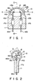
- Figs. 1 and 2 collectively show an arc tube bulb of a metal halide lamp according to a first embodiment of the present invention.
- the lamp has an input power of 150 W.
- a reference numeral 10 shown in the drawing denotes an arc tube bulb formed of a quartz glass.
- a sealed portion 11 is formed by pinch sealing at only one end of the arc tube bulb 10, with an enclosure portion 13 defining a discharge space 12 being formed at the other end of the bulb.
- the enclosure portion 13 is in the shape of a somewhat deformed sphere and, thus, looks oblong or circular depending on the viewing angle.
- the discharge space 12 defined by the enclosure portion has an inner volume of 0.5 cc.
- a bulb axis O-O extends along the longer axis of the oblong enclosure portion 13, and the sealed portion 11 is formed at one end of the bulb 10 in a direction perpendicular to the bulb axis O-O.
- the sealed portion 11 is formed by pinching and, thus, has flat surfaces.
- a pair of electrodes 14a, 14b are arranged apart from each other along the bulb axis O-O within the bulb 10. Each of these electrodes 14a, 14b is sealed in the sealed portion 11 formed by pinching.
- These electrodes comprise electrode rods 15a, 15b, and electrode coils 16a, 16b mounted at the tips of the electrodes 15a and 15b, respectively. In the embodiment shown in Figs.
- the rods 15a, 15b are formed separately from the coils 16a, 16b. It should be noted that each of these rods 15a and 15b is formed of a pure rhenium metal or a rhenium-tungsten alloy and is bent at the tip portion. Each of the coils 16a, 16b is formed by winding wires 116a, 116b each consisting of a pure tungsten or thoriated tungsten. The tungsten or thoriated tungsten wire is wound 3 or 4 turns about the bent tip portion of the electrode rod so as to form the coil.
- each of the coils 16a, 16b has an outer diameter d3 of 1.5 mm. It should be noted that the coils 16a, 16b are apart from each other by about 6.8 mm within the discharge space along the bulb axis O-O.
- Metal foils 17a, 17b formed of, for example, molybdenum are buried apart from each other within the sealed portion 11 formed by pinching.
- the rods 15a, 15b which are positioned apart from each other by a distance greater than the distance between the tips of the coils 16a, 16b, are connected at the proximal ends to the metal foils 17a, 17b, respectively.
- the metal foils 17a, 17b are respectively connected to outer lead wires 18a, 18b extending to the outside.
- a starter rare gas, a predetermined amount of mercury and a metal halide such as SnI2, NaI, TlI, InI, NaBr or LiBr are sealed in the bulb 10.
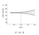
- the relationship between the maximum inner diameter of the discharge space 12 and the outer diameter of the coil 16a or 16b is determined to meet the condition given below: d3/D ⁇ 0.2 (1) where, D is the maximum inner diameter of the arc tube bulb 10 in the discharge space 12 in a direction perpendicular to the arc in the center of the light emitting region, i.e., in the center between the pair of coils 16a, 16b, and d3 is the outer diameter of the coil 16a or 16b.
- the maximum inner diameter of the arc tube bulb 10 is 13 mm, the value of d3/D 0.115 or less.
- the lamp current during the stable lighting stage is set at 1.8 A, and the input power of the lamp in this stage is set at 150 W.
- the inner surface area S of the discharge space 12 is about 3.5 cm2, and the lamp load per unit surface area of the light emitting bulb is about 43 W/cm2.
- the value of the lamp load given above is about twice the lamp load of the conventional metal halide lamp sealed at both ends.
- each of the rods 15a, 15b of the electrodes 14a, 14b is formed of a pure rhenium wire. Since rhenium is oxidized at a high temperature, the rods 15a, 15b are less likely to be oxidized when heated for softening the bulb 10 in the step of forming the sealed portion 11 by pinching. As a result, the material of these rods is less likely to be scattered so as to be attached to the inner surface of the enclosure portion 13, leading to a high lumen maintenance factor of the lamp.
- the rods 15a, 15b formed of rhenium serve to suppress the heat conduction from the coils 16a, 16b to these rods. Naturally, the temperature elevation of these rods is suppressed during the lighting of the lamp, with the result that the arc spot is not transferred to a space between these rods 15a and 15b. It follows that it is possible to prevent the discharge occurrence between the rods and, thus, to prevent these rods from being thinned and finally being broken. Since the rods 15a, 15b are not broken, the life of the lamp is prolonged.
- d1 is the diameter of the rods 15a, 15b
- I is the lamp current during the stable lighting of the lamp.
- the value of I/d1 is 3.6.
- the rod has a large diameter d1
- the heat capacity of the rod is increased, making it possible to suppress the temperature elevation of the rod.
- the scattering of the rod material and the thinning of the rod can be prevented, leading to a high lumen maintenance factor.
- the life of the lamp can be prolonged.
- the diameter d1 of the rod is unduly large, the electrode temperature is excessively lowered, resulting in an abrupt interruption of lighting. In addition, the halogen cycle is impaired.
- the present inventors have made an extensive research so as to find that it is desirable for the relationship between the diameter d1 (mm ) of the rods 15a, 15b and the lamp current I (amperes) during the stable lighting of the lamp to meet the condition 2.4 ⁇ I/d1 ⁇ 4.5. This is the case with not only a metal halide lamp having an input power of 150 W but also lamps of other rated input power.
- the diameter d2 of the wire forming the coils 16a, 16b is large, the heat capacity of the coils is increased so as to suppress the temperature elevation of the coils. As a result, the arc spot is unlikely to be generated on the coils. It follows that it is possible to maintain a stable discharge, if the diameter d2 of the wire forming the coils is made equal to or smaller than the diameter d1 of the rods 15a, 15b so as to meet the condition given above, i.e., 0.3 ⁇ d2/d1 ⁇ 1.
- the relationship between the maximum diameter D of the arc tube bulb 10 in the discharge space 12 in a direction perpendicular to the arc in the light emitting center and the outer diameter d3 of the coils 16a, 16b is defined to meet the condition "d3/D ⁇ 0.2" in the present invention, as pointed out previously.
- the arc generated between the coils 16a and 16b is positioned a large distance apart from the inner wall of the arc tube bulb 10 in the present invention, with the result that, even if the arc spot is moved on the surfaces of the coils 16a, 16b, it is possible to suppress the heating of the arc tube bulb 10 caused by the heat of the arc.
- the coolest portions are formed in the arc tube bulb 10 at points P, P rearward of the electrode coils 16a, 16b which are positioned far apart from the arc.
- the coolest portions P, P are not moved even if the arc is moved, with the result that the temperature of the coolest points is not changed so as to suppress the changes in the lamp voltage and in the light emitting characteristics.
- the wall of the arc tube bulb 10 is not locally heated by the arc so as to prevent the local thermal expansion of the bulb wall.
- Fig. 3 is a graph showing the changes in the lamp voltage V L relative to the change in the ratio of the coil outer diameter d3 to the maximum inner diameter D of the discharge space, i.e., V L vs d3/D.
- the range of variation represented by the shaded region in the graph of Fig. 3 denotes the average value of the deviation resulting from 10 times of measurements. It is seen that the range of variation is increased with increase in the value of d3/D.
- Table 1 shows experimental data on the relationship between the ratio d3/D and the swelling of the light emitting bulb 10: Table 1 d3/D Lighting Time (Hours) 0 1000 2000 3000 6000 0.05 no swelling no swelling no swelling no swelling no swelling 0.10 no swelling no swelling no swelling no swelling no swelling 0.20 no swelling no swelling no swelling no swelling 0.25 no swelling no swelling no swelling no swelling swollen 0.30 no swelling no swelling no swelling swollen swollen 0.40 no swelling swollen swollen swollen swollen swollen
- the electrode rods 15a, 15b are formed of a pure rhenium. Alternatively, it is possible to use a rhenium-tungsten alloy as a material of these rods. Even in this case, the present invention produces prominent effects, compared with the prior art in which the electrode rod is formed of a pure tungsten or thoriated tungsten.
- the mixing ratio of rhenium to tungsten should be 0.05 or more by weight. If the Re/W ratio is smaller than 0.05, the rhenium amount is insufficient for achieving the object of the rhenium addition. In other words, the electrode material tends to be scattered and the electrode rod is likely to be thinned, resulting in reduction in the lumen maintenance factor. In addition, the electrode rod tends to be broken, leading to a short life of the lamp.
- Table 2 shows the experimental data on the effect of the Re/W mixing ratio: Table 2 Re/W Mixing Ratio Electrode Breakage Occurence Evaluation after 3000 hrs after 6000 hrs 0.01 4/10 8/10 x 0.03 0/10 2/10 x 0.05 0/10 0/10 good 0.1 0/10 0/10 good 0.1 0/10 0/10 good 0.3 0/10 0/10 good Note: x ... impossible to evaluate
- Fig. 4 shows a second embodiment of the present invention.
- the second embodiment differs from the first embodiment shown in Figs. l and 2 in that the coils 16a, 16b are integral with the rods 15a, 15b so as to form the electrodes 14a, 14b, respectively.
- the integral structure of the coil and the rod is formed of a pure rhenium metal or a rhenium-tungsten alloy.
- the effects produced by the first embodiment are also produced by the second embodiment.
- the coils 16a, 16b are prevented from being excessively heated during the lighting of the lamp in the second embodiment, making it possible to suppress the heat conduction from the coils 16a, 16b to the rods 15a, 15b. As a result, it is possible to prevent the temperature elevation of the rods 15a, 15b.
- Fig. 5 shows a third embodiment of the present invention.
- the third embodiment differs from the first embodiment in that the coils 16a, 16b are integral with the rods 15a, 15b so as to form the electrodes 14a, 14b, respectively, and that the integral structure of the coil and the rod is formed of a pure tungsten metal or a thoriated tungsten.
- the rods 15a, 15b are covered with tubes 20a, 20b, respectively, said tubes being formed of a pure rhenium metal or a rhenium-tungsten alloy.
- the electrodes 14a, 14b are inserted into the bulb through the open end of the bulb which has not yet been sealed, and the rods 15a, 15b are heated.
- the rods 15a, 15b which are formed of tungsten, are not oxidized even if these rods are heated because these rods are covered with the tubes 20a, 20b formed of a pure rhenium metal or a rhenium-tungsten alloy.
- the tubes 20a, 20b are not oxidized either because a pure rhenium metal or a rhenium-tungsten alloy is unlikely to be oxidized.
- the scattering of the materials of the rods 15a, 15b and the tubes 20a, 20b is suppressed during the lighting of the lamp so as to prevent the blackening of the bulb and, thus, to improve the lumen maintenance factor.
- the covering film noted above can be formed by means of plating, coating of a powdery material or the like.
- Fig. 6 shows a fourth embodiment of the present invention.
- the fourth embodiment differs from the first embodiment shown in Figs. 1 and 2 in that the pair of electrode rods 15a, 15b are bent backward at the point where these rods extending from the sealed portion 11 enter the discharge space 12.
- the rods 15a, 15b are bent such that the pair of coils 16a, 16b are moved away from each other and these rods extend along the inner surface of the enclosure portion 13. Since the rods 15a, 15b are bent in a manner to extend along the inner surface of the bulb 10, the bent portions 30a, 30b of the rods 15a, 15b are positioned close to those portions of the bulb wall which are positioned on the bulb axis O-O.
- the bulb wall is warmed by the heat of radiation emitted from the bent portions 30a, 30b of the rods 15a, 15b. It follows that the coolest portions P, P facing the bent portions 30a, 30b are warmed, with the result that the vapor pressure within the discharge space 12 is increased so as to improve the light emitting efficacy and the color rendering properties of the lamp.
- the coils 16a, 16b are positioned sufficiently apart from each other in the fourth embodiment shown in Fig. 6 because the rods 15a, 15b are bent in a manner to extend along the inner surface of the bulb 10. This is effective in that, even if the bulb 10 is small, it is possible to provide a large free space between the electrodes. In other words, it is possible to ensure a large arc length, leading to an improved light emitting efficacy.
- Fig. 7 shows a fifth embodiment of the present invention.
- the fifth embodiment which is a modification of the fourth embodiment shown in Fig. 6, differs from the fourth embodiment in that, in the fifth embodiment, the rods 15a, 15b are bent such that only the portions 31a, 31b rearward of the coils 16a, 16b are positioned close to the bulb wall, though the rods are bent in the fourth embodiment shown in Fig. 6 such that the rods extend along the inner surface of the bulb 10.
- each of the rods and the coils may be formed of a single wire material so as to provide the electrode 14 of an integral structure in each of the embodiments of Figs. 6 and 7.
- the input power WL (watt) of the lamp divided by the inner surface area S (cm2) of the discharge space 12, i.e., the value of WL/S, is defined to fall within the range of between 20 and 70 W/cm2 in the present invention. Particularly, it is desirable for the value of WL/S to fall within the range of between 20 and 50 W/cm2.
Landscapes
- Chemical & Material Sciences (AREA)
- Engineering & Computer Science (AREA)
- Materials Engineering (AREA)
- Mechanical Engineering (AREA)
- Metallurgy (AREA)
- Organic Chemistry (AREA)
- Discharge Lamp (AREA)
- Vessels And Coating Films For Discharge Lamps (AREA)
- Discharge Lamps And Accessories Thereof (AREA)
Applications Claiming Priority (6)
| Application Number | Priority Date | Filing Date | Title |
|---|---|---|---|
| JP129902/88 | 1988-05-27 | ||
| JP63129902A JPH01298638A (ja) | 1988-05-27 | 1988-05-27 | 小形金属蒸気放電灯 |
| JP194573/88 | 1988-08-05 | ||
| JP63194573A JPH07118304B2 (ja) | 1988-08-05 | 1988-08-05 | 小形金属蒸気放電灯 |
| JP300013/88 | 1988-11-28 | ||
| JP63300013A JP2630642B2 (ja) | 1988-11-28 | 1988-11-28 | 小形メタルハライドランプ |
Publications (2)
| Publication Number | Publication Date |
|---|---|
| EP0343625A2 true EP0343625A2 (de) | 1989-11-29 |
| EP0343625A3 EP0343625A3 (de) | 1991-04-24 |
Family
ID=27316016
Family Applications (1)
| Application Number | Title | Priority Date | Filing Date |
|---|---|---|---|
| EP19890109379 Withdrawn EP0343625A3 (de) | 1988-05-27 | 1989-05-24 | Einseitig gequetschte Metallhalogenidlampe |
Country Status (3)
| Country | Link |
|---|---|
| US (1) | US4973880A (de) |
| EP (1) | EP0343625A3 (de) |
| KR (1) | KR910010108B1 (de) |
Cited By (7)
| Publication number | Priority date | Publication date | Assignee | Title |
|---|---|---|---|---|
| EP0418877A3 (en) * | 1989-09-20 | 1991-08-07 | Toshiba Lighting & Technology Corporation | Single-sealed metal vapor electric discharge lamp |
| EP0438060A3 (en) * | 1990-01-14 | 1991-10-16 | Toshiba Lighting & Technology Corporation | Metal vapor discharge lamp of a single end type |
| EP0381035B1 (de) * | 1989-01-31 | 1994-08-03 | Toshiba Lighting & Technology Corporation | Einseitig gequetschte Metalldampfentladungslampe |
| EP0378338B1 (de) * | 1989-01-12 | 1997-04-02 | Tokyo Densoku Kabushiki Kaisha | Entladungsröhre |
| US6060829A (en) * | 1997-02-24 | 2000-05-09 | U.S. Philips Corporation | Metal halide lamp with rhenium skin on tungsten electrode |
| EP1154460A1 (de) * | 2000-05-08 | 2001-11-14 | Welch Allyn, Inc. | Elektrode für Lampe mit Quarzkolben |
| EP1019948B1 (de) * | 1998-08-06 | 2004-09-15 | Patent-Treuhand-Gesellschaft für elektrische Glühlampen mbH | Hochdrucklampe mit langer lebensdauer |
Families Citing this family (3)
| Publication number | Priority date | Publication date | Assignee | Title |
|---|---|---|---|---|
| US5834895A (en) * | 1990-10-25 | 1998-11-10 | Fusion Lighting, Inc. | Visible lamp including selenium |
| DE10028089B4 (de) * | 1999-06-10 | 2010-12-09 | Toshiba Lighting & Technology Corp. | Beleuchtungseinrichtung mit einer Hochleistungs-Entladungslampe |
| US6815888B2 (en) | 2001-02-14 | 2004-11-09 | Advanced Lighting Technologies, Inc. | Halogen lamps, fill material and methods of dosing halogen lamps |
Family Cites Families (8)
| Publication number | Priority date | Publication date | Assignee | Title |
|---|---|---|---|---|
| JPS5215910A (en) * | 1975-07-25 | 1977-02-05 | Nissan Motor Co Ltd | Multi-point ignition engine having sub-chamber |
| JPS5254167A (en) * | 1975-10-28 | 1977-05-02 | Sharp Kk | Printed substrate wiring pattern system |
| US4320322A (en) * | 1980-03-24 | 1982-03-16 | Gte Products Corporation | Electrode geometry to improve arc stability |
| US4620130A (en) * | 1984-03-27 | 1986-10-28 | Gte Products Corporation | Electrode alignment and capsule design for single-ended low wattage metal halide lamps |
| US4636687A (en) * | 1984-03-27 | 1987-01-13 | Gte Products Corporation | Electrode alignment and capsule design for single-ended low wattage metal halide lamps |
| DE3537872A1 (de) * | 1985-10-24 | 1987-04-30 | Patent Treuhand Ges Fuer Elektrische Gluehlampen Mbh | Hochdruckentladungslampe |
| DE3620961A1 (de) * | 1986-06-23 | 1988-01-14 | Patent Treuhand Ges Fuer Elektrische Gluehlampen Mbh | Metallhalogenidhochdruckentladungslampe |
| US4998036A (en) * | 1987-12-17 | 1991-03-05 | Kabushiki Kaisha Toshiba | Metal vapor discharge lamp containing an arc tube with particular bulb structure |
-
1989
- 1989-05-23 KR KR1019890006909A patent/KR910010108B1/ko not_active Expired
- 1989-05-24 EP EP19890109379 patent/EP0343625A3/de not_active Withdrawn
- 1989-05-25 US US07/356,874 patent/US4973880A/en not_active Expired - Fee Related
Cited By (11)
| Publication number | Priority date | Publication date | Assignee | Title |
|---|---|---|---|---|
| EP0378338B1 (de) * | 1989-01-12 | 1997-04-02 | Tokyo Densoku Kabushiki Kaisha | Entladungsröhre |
| EP0381035B1 (de) * | 1989-01-31 | 1994-08-03 | Toshiba Lighting & Technology Corporation | Einseitig gequetschte Metalldampfentladungslampe |
| EP0418877A3 (en) * | 1989-09-20 | 1991-08-07 | Toshiba Lighting & Technology Corporation | Single-sealed metal vapor electric discharge lamp |
| US5138229A (en) * | 1989-09-20 | 1992-08-11 | Toshiba Lighting & Technology Corporation | Single-sealed metal vapor electric discharge lamp |
| EP0438060A3 (en) * | 1990-01-14 | 1991-10-16 | Toshiba Lighting & Technology Corporation | Metal vapor discharge lamp of a single end type |
| US5138218A (en) * | 1990-01-14 | 1992-08-11 | Toshiba Lighting And Technology Corporation | Metal vapor discharge lamp having single end arc tube of predetermined thickness |
| US6060829A (en) * | 1997-02-24 | 2000-05-09 | U.S. Philips Corporation | Metal halide lamp with rhenium skin on tungsten electrode |
| EP1019948B1 (de) * | 1998-08-06 | 2004-09-15 | Patent-Treuhand-Gesellschaft für elektrische Glühlampen mbH | Hochdrucklampe mit langer lebensdauer |
| EP1154460A1 (de) * | 2000-05-08 | 2001-11-14 | Welch Allyn, Inc. | Elektrode für Lampe mit Quarzkolben |
| US6626725B1 (en) | 2000-05-08 | 2003-09-30 | Welch Allyn, Inc | Electrode treatment surface process for reduction of a seal cracks in quartz |
| US6774565B2 (en) | 2000-05-08 | 2004-08-10 | Welch Allyn, Inc. | Electrode surface treatment process |
Also Published As
| Publication number | Publication date |
|---|---|
| US4973880A (en) | 1990-11-27 |
| KR890017759A (ko) | 1989-12-18 |
| KR910010108B1 (ko) | 1991-12-16 |
| EP0343625A3 (de) | 1991-04-24 |
Similar Documents
| Publication | Publication Date | Title |
|---|---|---|
| JP3152950B2 (ja) | 低電力金属ハロゲン化物ランプ | |
| JPS6337721Y2 (de) | ||
| US6337539B1 (en) | Low-pressure mercury vapor discharge lamp and illuminator | |
| US5841229A (en) | Amalgam support arrangement for an electrodeless discharge lamp | |
| JPH0531264B2 (de) | ||
| US5783912A (en) | Electrodeless fluorescent lamp having feedthrough for direct connection to internal EMI shield and for supporting an amalgam | |
| EP0343625A2 (de) | Einseitig gequetschte Metallhalogenidlampe | |
| JP2947958B2 (ja) | 高圧放電ランプ | |
| EP1032010A1 (de) | Wasserfreie silberhalogenidlampe | |
| EP0381035B1 (de) | Einseitig gequetschte Metalldampfentladungslampe | |
| US7423379B2 (en) | High-pressure gas discharge lamp having tubular electrodes | |
| EP1220296A1 (de) | Wärmeisolierender Zuleitungsdraht zur Stromversorgung von Elektroden in einer Keramikmetallhalogenidlampe | |
| US6650042B2 (en) | Low-wattage fluorescent lamp | |
| JP2000268773A (ja) | メタルハライドランプ | |
| EP0418877B2 (de) | Einseitig gequetschte elektrische Metalldampfentladungslampe | |
| JP2002528879A (ja) | 低圧水銀蒸気放電ランプ | |
| JP2003151492A (ja) | ショートアーク型超高圧放電ランプ | |
| EP2239761A2 (de) | Hochdruckentladungslampe und Beleuchtungsvorrichtung | |
| JP2003272560A (ja) | メタルハライドランプ | |
| US6366020B1 (en) | Universal operating DC ceramic metal halide lamp | |
| EP0382516A2 (de) | Metallhalogenidlampe mit Beibehaltung eines Hochleuchterhaltungsfaktors über eine verlängerte Betriebsperiode | |
| JPH0877967A (ja) | 水銀放電ランプ | |
| JPH07118304B2 (ja) | 小形金属蒸気放電灯 | |
| JPH11162406A (ja) | 高圧放電ランプおよび投光装置ならびにプロジェクタ装置 | |
| JP2668434B2 (ja) | メタルハライドランプ |
Legal Events
| Date | Code | Title | Description |
|---|---|---|---|
| PUAI | Public reference made under article 153(3) epc to a published international application that has entered the european phase |
Free format text: ORIGINAL CODE: 0009012 |
|
| 17P | Request for examination filed |
Effective date: 19890621 |
|
| AK | Designated contracting states |
Kind code of ref document: A2 Designated state(s): DE GB |
|
| PUAL | Search report despatched |
Free format text: ORIGINAL CODE: 0009013 |
|
| AK | Designated contracting states |
Kind code of ref document: A3 Designated state(s): DE GB |
|
| 17Q | First examination report despatched |
Effective date: 19930629 |
|
| STAA | Information on the status of an ep patent application or granted ep patent |
Free format text: STATUS: THE APPLICATION IS DEEMED TO BE WITHDRAWN |
|
| 18D | Application deemed to be withdrawn |
Effective date: 19931110 |