EP0343534B1 - Container for preserving liquids, in particular bodily liquids - Google Patents
Container for preserving liquids, in particular bodily liquids Download PDFInfo
- Publication number
- EP0343534B1 EP0343534B1 EP89109066A EP89109066A EP0343534B1 EP 0343534 B1 EP0343534 B1 EP 0343534B1 EP 89109066 A EP89109066 A EP 89109066A EP 89109066 A EP89109066 A EP 89109066A EP 0343534 B1 EP0343534 B1 EP 0343534B1
- Authority
- EP
- European Patent Office
- Prior art keywords
- tube
- cap
- closure
- locking
- closure cap
- Prior art date
- Legal status (The legal status is an assumption and is not a legal conclusion. Google has not performed a legal analysis and makes no representation as to the accuracy of the status listed.)
- Expired - Lifetime
Links
- 239000007788 liquid Substances 0.000 title description 32
- 238000007789 sealing Methods 0.000 claims description 5
- 210000001124 body fluid Anatomy 0.000 claims description 4
- 239000010839 body fluid Substances 0.000 claims description 4
- 230000000295 complement effect Effects 0.000 claims description 4
- 238000000034 method Methods 0.000 claims description 4
- 239000012530 fluid Substances 0.000 claims 5
- 239000008280 blood Substances 0.000 description 10
- 210000004369 blood Anatomy 0.000 description 10
- 238000004519 manufacturing process Methods 0.000 description 2
- 210000003462 vein Anatomy 0.000 description 2
- LFQSCWFLJHTTHZ-UHFFFAOYSA-N Ethanol Chemical compound CCO LFQSCWFLJHTTHZ-UHFFFAOYSA-N 0.000 description 1
- 238000013475 authorization Methods 0.000 description 1
- 238000010241 blood sampling Methods 0.000 description 1
- 230000006378 damage Effects 0.000 description 1
- 238000006073 displacement reaction Methods 0.000 description 1
- 208000015181 infectious disease Diseases 0.000 description 1
- 230000002458 infectious effect Effects 0.000 description 1
- 239000000463 material Substances 0.000 description 1
- 210000003296 saliva Anatomy 0.000 description 1
- 238000000926 separation method Methods 0.000 description 1
- 239000000126 substance Substances 0.000 description 1
- 210000002700 urine Anatomy 0.000 description 1
Images

Classifications
-
- A—HUMAN NECESSITIES
- A61—MEDICAL OR VETERINARY SCIENCE; HYGIENE
- A61B—DIAGNOSIS; SURGERY; IDENTIFICATION
- A61B5/00—Measuring for diagnostic purposes; Identification of persons
- A61B5/15—Devices for taking samples of blood
- A61B5/153—Devices specially adapted for taking samples of venous or arterial blood, e.g. with syringes
-
- A—HUMAN NECESSITIES
- A61—MEDICAL OR VETERINARY SCIENCE; HYGIENE
- A61B—DIAGNOSIS; SURGERY; IDENTIFICATION
- A61B10/00—Instruments for taking body samples for diagnostic purposes; Other methods or instruments for diagnosis, e.g. for vaccination diagnosis, sex determination or ovulation-period determination; Throat striking implements
- A61B10/0045—Devices for taking samples of body liquids
-
- A—HUMAN NECESSITIES
- A61—MEDICAL OR VETERINARY SCIENCE; HYGIENE
- A61B—DIAGNOSIS; SURGERY; IDENTIFICATION
- A61B5/00—Measuring for diagnostic purposes; Identification of persons
- A61B5/15—Devices for taking samples of blood
- A61B5/150007—Details
- A61B5/150015—Source of blood
- A61B5/15003—Source of blood for venous or arterial blood
-
- A—HUMAN NECESSITIES
- A61—MEDICAL OR VETERINARY SCIENCE; HYGIENE
- A61B—DIAGNOSIS; SURGERY; IDENTIFICATION
- A61B5/00—Measuring for diagnostic purposes; Identification of persons
- A61B5/15—Devices for taking samples of blood
- A61B5/150007—Details
- A61B5/150206—Construction or design features not otherwise provided for; manufacturing or production; packages; sterilisation of piercing element, piercing device or sampling device
- A61B5/150259—Improved gripping, e.g. with high friction pattern or projections on the housing surface or an ergonometric shape
-
- A—HUMAN NECESSITIES
- A61—MEDICAL OR VETERINARY SCIENCE; HYGIENE
- A61B—DIAGNOSIS; SURGERY; IDENTIFICATION
- A61B5/00—Measuring for diagnostic purposes; Identification of persons
- A61B5/15—Devices for taking samples of blood
- A61B5/150007—Details
- A61B5/150351—Caps, stoppers or lids for sealing or closing a blood collection vessel or container, e.g. a test-tube or syringe barrel
-
- A—HUMAN NECESSITIES
- A61—MEDICAL OR VETERINARY SCIENCE; HYGIENE
- A61B—DIAGNOSIS; SURGERY; IDENTIFICATION
- A61B5/00—Measuring for diagnostic purposes; Identification of persons
- A61B5/15—Devices for taking samples of blood
- A61B5/150007—Details
- A61B5/150374—Details of piercing elements or protective means for preventing accidental injuries by such piercing elements
- A61B5/150381—Design of piercing elements
- A61B5/150389—Hollow piercing elements, e.g. canulas, needles, for piercing the skin
-
- A—HUMAN NECESSITIES
- A61—MEDICAL OR VETERINARY SCIENCE; HYGIENE
- A61B—DIAGNOSIS; SURGERY; IDENTIFICATION
- A61B5/00—Measuring for diagnostic purposes; Identification of persons
- A61B5/15—Devices for taking samples of blood
- A61B5/150007—Details
- A61B5/150374—Details of piercing elements or protective means for preventing accidental injuries by such piercing elements
- A61B5/150381—Design of piercing elements
- A61B5/150473—Double-ended needles, e.g. used with pre-evacuated sampling tubes
- A61B5/150496—Details of construction of hub, i.e. element used to attach the double-ended needle to a piercing device or sampling device
-
- A—HUMAN NECESSITIES
- A61—MEDICAL OR VETERINARY SCIENCE; HYGIENE
- A61B—DIAGNOSIS; SURGERY; IDENTIFICATION
- A61B5/00—Measuring for diagnostic purposes; Identification of persons
- A61B5/15—Devices for taking samples of blood
- A61B5/150007—Details
- A61B5/150374—Details of piercing elements or protective means for preventing accidental injuries by such piercing elements
- A61B5/150534—Design of protective means for piercing elements for preventing accidental needle sticks, e.g. shields, caps, protectors, axially extensible sleeves, pivotable protective sleeves
- A61B5/150572—Pierceable protectors, e.g. shields, caps, sleeves or films, e.g. for hygienic purposes
-
- B—PERFORMING OPERATIONS; TRANSPORTING
- B65—CONVEYING; PACKING; STORING; HANDLING THIN OR FILAMENTARY MATERIAL
- B65D—CONTAINERS FOR STORAGE OR TRANSPORT OF ARTICLES OR MATERIALS, e.g. BAGS, BARRELS, BOTTLES, BOXES, CANS, CARTONS, CRATES, DRUMS, JARS, TANKS, HOPPERS, FORWARDING CONTAINERS; ACCESSORIES, CLOSURES, OR FITTINGS THEREFOR; PACKAGING ELEMENTS; PACKAGES
- B65D41/00—Caps, e.g. crown caps or crown seals, i.e. members having parts arranged for engagement with the external periphery of a neck or wall defining a pouring opening or discharge aperture; Protective cap-like covers for closure members, e.g. decorative covers of metal foil or paper
- B65D41/32—Caps or cap-like covers with lines of weakness, tearing-strips, tags, or like opening or removal devices, e.g. to facilitate formation of pouring openings
- B65D41/34—Threaded or like caps or cap-like covers provided with tamper elements formed in, or attached to, the closure skirt
- B65D41/3442—Threaded or like caps or cap-like covers provided with tamper elements formed in, or attached to, the closure skirt with rigid bead or projections formed on the tamper element and coacting with bead or projections on the container
- B65D41/3447—Threaded or like caps or cap-like covers provided with tamper elements formed in, or attached to, the closure skirt with rigid bead or projections formed on the tamper element and coacting with bead or projections on the container the tamper element being integrally connected to the closure by means of bridges
Definitions
- the invention relates to a liquid storage container according to the preamble of claim 1.
- Such liquid storage containers are e.g. used to transport body fluids taken by a doctor or nurse to a test laboratory.
- the body fluids filled into the tube can be urine, saliva or blood.
- such liquid storage containers have a removable closure at their open end, while they are sealed liquid-tight at the other end. By opening the cap at the front end, the liquid can be filled into the tube, then the cap is attached and the tube is sent to a laboratory, where the cap is removed and the liquid is removed before or after handling e.g. is used in a centrifuge for further use.
- a problem with such liquid storage containers is that any manipulation should be avoided in the sense that after the authorized person closes the tube filled with liquid until the liquid receiving container arrives in the laboratory, each opening of the container is prevented or at least designed in this way, that it will be recognized when the tube arrives in the laboratory. This is to prevent unauthorized persons from either exchanging the liquid in the tube for another one or from adding any other substances into the tube.
- a liquid storage container is known with a cylindrical tube open on one side, which is liquid-tightly closed by a closure provided at the front end of the tube for the filling or removal of liquid, and with a closure at the front end of the tube Tube-attachable cap.
- the closure cap and the closure can be unscrewed from the container and screwed back onto it, which means that the contents of the container can be manipulated without this being apparent later.
- a closable container for the safe reception of infectious laboratory material which consists of a receptacle and a lid which can be inseparably connected to the receptacle via a snap closure.
- the container has no closure cap in addition to the lid.
- the aim of the invention is therefore to provide a liquid storage container of the type mentioned at the outset, which cannot be manipulated by unauthorized persons after the filling of a liquid and the attachment of the closure so that the contents of the container can be falsified, an unauthorized opening made at the destination should be easily recognized.
- the idea of the invention is therefore to be seen in the fact that the authorized person, who has filled the tube with liquid and applied the closure, can push the closure cap according to the invention by hand, ie without tools, onto the front end of the closed tube, the locking ring thus on that snaps on the tube provided locking means that a removal of the cap without destroying the tearable connection between the locking ring and the cap is not possible.
- persons who want to open the container without authorization are warned to do so because they are unable to close the broken desired tear connection between the closure cap and the locking ring again. So should an unauthorized person nonetheless separate the cap from that Tear off the snap ring, this is recognized at the destination, for example in the examination laboratory, and the liquid in the tube can be discarded as unsuitable for the examination. It is then possible to request a new liquid sample from the sender immediately.
- the ring projection can be integrally molded in one piece with the manufacture of the plastic tube.
- the ring projection is preferably coaxial to the circular cylindrical tube and has a uniform width and thickness.
- the invention is used with particular advantage in the case of a liquid receiving container with a screw cap which engages over the front end of the tube as a closure.
- Such liquid receptacles are often used for blood sampling (DE-PS 29 48 653).
- the invention can also be used with particular advantage in the case of liquid holding containers which have a projection, preferably cylindrical, projecting from the closure and having an axial through-channel, in which a closure member which can be pierced from the rear end of a cannula sharpened on both sides is arranged (DE-PS 29 48 653 ).
- the measures according to claim 5 can expediently also be provided, which prevent blood escaping in the region of the closure member from further leakage.
- the screw cap applied to the tube generally has a surface profile consisting of axial ribs.
- the invention provides for a non-rotatable connection between the attached cap and the screw cap, which allows the cap to be unscrewed by rotating the cap.
- the cap also serves as a tool for actuating the screw cap.
- a screw cap 12 is screwed onto the front end of the tube 11, which is provided with an external thread, and which integrally carries a circular cylindrical projection 18 projecting axially forward, in which an axial through channel 22 is provided, which in turn is closed at its front end by an elastic closure member 20 is.
- the screw cap 12 is now unscrewed by gripping the cap 14 at the level of the screw cap 12 with two fingers and rotating it counterclockwise.
- the torque exerted on the closure cap 14 is transmitted to the screw cap 12 and axially removed from the tube 11. Since the locking projections 16 engage axially undetachably behind the ring projection 15, the predetermined breaking points 29 break open during the unscrewing process, and the closure cap 14 is separated from the locking ring 13, which due to the structural design described between the ring projection 15 and the cover ring 17 remains held.
- a removal of the closure cap 14 is also not possible in that a tool is guided from behind behind the locking ring 13 because this is prevented by the cover ring 17 integral with the tube 11.
- the cap projection 21 can also be designed such that it can be placed in a sealing manner on a conventional cannula cone on the front of the screw cap 12.
- the cap projection 21 would be designed to be complementary to the outer shape of the cannula attachment.
Landscapes
- Health & Medical Sciences (AREA)
- Life Sciences & Earth Sciences (AREA)
- Engineering & Computer Science (AREA)
- Medical Informatics (AREA)
- Surgery (AREA)
- Hematology (AREA)
- Veterinary Medicine (AREA)
- Pathology (AREA)
- Biomedical Technology (AREA)
- Heart & Thoracic Surgery (AREA)
- Public Health (AREA)
- Molecular Biology (AREA)
- General Health & Medical Sciences (AREA)
- Animal Behavior & Ethology (AREA)
- Physics & Mathematics (AREA)
- Biophysics (AREA)
- Mechanical Engineering (AREA)
- Manufacturing & Machinery (AREA)
- Medical Preparation Storing Or Oral Administration Devices (AREA)
- Closures For Containers (AREA)
Description
Die Erfindung betrifft einen Flüssigkeitsaufbewahrungsbehälter nach dem Oberbegriff des Patentanspruchs 1.The invention relates to a liquid storage container according to the preamble of claim 1.
Derartige Flüssigkeitsaufbewahrungsbehälter werden z.B. zum Transport von durch einen Arzt oder eine Krankenschweste reinem Patienten abgenommene Körperflüssigkeiten zu einem Untersuchungslabor verwendet. Bei den in das Röhrchen eingefüllten Körperflüssigkeiten kann es sich um Urin, Speichel oder Blut handeln. Im allgemeinen weisen derartige Flüssigkeitsaufbewhrungsbehälter an ihrem offenen Ende einen abnehmbaren Verschluß auf, während sie am anderen Ende flüssigkeitsdicht verschlossen sind. Durch Öffnen des Verschlusses am vorderen Ende kann die Flüssigkeit in das Röhrchen eingefüllt werden, worauf dann der Verschluß angebracht und das Röhrchen zu einem Labor geschickt wird, wo der Verschluß entfernt und die Flüssigkeit vor oder nach einer Handhabung z.B. in einer Zentrifuge einer weiteren Nutzung zugeführtw ird.Such liquid storage containers are e.g. used to transport body fluids taken by a doctor or nurse to a test laboratory. The body fluids filled into the tube can be urine, saliva or blood. In general, such liquid storage containers have a removable closure at their open end, while they are sealed liquid-tight at the other end. By opening the cap at the front end, the liquid can be filled into the tube, then the cap is attached and the tube is sent to a laboratory, where the cap is removed and the liquid is removed before or after handling e.g. is used in a centrifuge for further use.
Ein Problem bei derartigen Flüssigkeitsaufbewahrungsbehältern besteht darin, daß jede Manipulation in dem Sinne vermieden werden sollte, daß nach dem Verschließen des mit Flüssigkeit gefüllten Röhrchens durch die befugte Person bis zum Eintreffen des Flüssigkeitsaufnahmebehälters im Labor jedes erneute Öffnen des Behälters verhindert oder zumindest so gestaltet wird, daß es bei der Ankunft des Röhrchens im Labor erkannt wird. Auf diese Weise soll verhindert werden, daß Unbefugte entweder die in dem Röhrchen befindliche FLüssigkeit gegen eine andere austauschen oder irgendwelche anderen Substanzen in das Röhrchen zusätzlich eingeben.A problem with such liquid storage containers is that any manipulation should be avoided in the sense that after the authorized person closes the tube filled with liquid until the liquid receiving container arrives in the laboratory, each opening of the container is prevented or at least designed in this way, that it will be recognized when the tube arrives in the laboratory. This is to prevent unauthorized persons from either exchanging the liquid in the tube for another one or from adding any other substances into the tube.
Derartige Manipulationen müssen z.B. befürchtet werden, wenn sich in dem Röhrchen eine einem Kraftfahrer abgenommene Blutprobe befindet, die im Labor auf Alkoholgehalt untersucht werden soll.Such manipulations must e.g. are feared if there is a blood sample taken from a driver in the tube which is to be tested in the laboratory for alcohol content.
Aus der FR-A-2 292 456 ist ein Flüssigkeitsaufbewahrungsbehälter mit einem einseitig offenen, zylindrischen Röhrchen bekannt, welches durch einen zum Einfüllen oder Entnehmen von Flüssigkeit abnehmbaren, am vorderen Ende des Röhrchens vorgesehene Verschluß flüssigkeitsdicht verschlossen ist, und mit einer am vorderen Ende des Röhrchens aufsetzbaren Verschlußkappe. Die Verschlußkappe und der Verschluß sind gemeinsam vom Behälter ab- und auch wieder auf diesen aufschraubbar, wodurch der Inhalt des Behälters manipuliert werden kann, ohne daß dies später erkennbar ist.From FR-A-2 292 456 a liquid storage container is known with a cylindrical tube open on one side, which is liquid-tightly closed by a closure provided at the front end of the tube for the filling or removal of liquid, and with a closure at the front end of the tube Tube-attachable cap. The closure cap and the closure can be unscrewed from the container and screwed back onto it, which means that the contents of the container can be manipulated without this being apparent later.
Aus der DE-A-3 505 892 ist ein verschließbarer Behälter zur sicheren Aufnahme von infektiösem Labormaterial bekannt, welcher aus einem Aufnahmegefäß und einem Deckel besteht, der über einen Schnappverschluß untrennbar mit dem Aufnahmegefäß verbunden werden kann. Der Behälter weist keine zusätzlich zum Deckel vorhandene Verschlußkappe auf.From DE-A-3 505 892 a closable container for the safe reception of infectious laboratory material is known, which consists of a receptacle and a lid which can be inseparably connected to the receptacle via a snap closure. The container has no closure cap in addition to the lid.
Das Ziel der Erfindung besteht somit darin, einen Flüssigkeitsaufbewahrungsbehälter der eingangs genannten Gattung zu schaffen, an dem durch unbefugte Personen nach dem Einfüllen einer Flüssigkeit und dem Anbringen des Verschlusses nicht unerkennbar in der Weise manipuliert werden kann, daß der Inhalt des Behälters verfälscht werden kann, wobei ein dennoch vorgenommenes unbefugtes Öffnen am Bestimmungsort ohne weiteres erkannt werden soll.The aim of the invention is therefore to provide a liquid storage container of the type mentioned at the outset, which cannot be manipulated by unauthorized persons after the filling of a liquid and the attachment of the closure so that the contents of the container can be falsified, an unauthorized opening made at the destination should be easily recognized.
Zur Lösung dieser Aufgabe sind die Merkmale des kennzeichnenden Teils des Patentanspruchs 1 vorgesehen.To achieve this object, the features of the characterizing part of claim 1 are provided.
Der Erfindungsgedanke ist also darin zu sehen, daß die befugte Person, welche das Röhrchen mit Flüssigkeit gefüllt und den Verschluß angebracht hat, die erfindungsgemäße Verschlußkappe von Hand, d.h. ohne Werkzeug auf das vordere Ende des verschlossenen Röhrchens aufschieben kann, wobei der Rastring so auf das am Röhrchen vorgesehene Rastmittel aufschnappt, dar ein Abnehmen der Verschlußkappe ohne Zerstörung der aufreißbaren Verbindung zwischen dem Rastring und der Verschlußkappe nicht möglich ist. Dadurch werden Personen, die den Behälter unbefugt öffnen wollen, gewarnt, dies zu tun, weil sie nicht in der Lage sind, die aufgebrochene Soll-Reiß-Verbindung zwischen der Verschlußkappe und dem Rastring wieder zu schließen. Sollte also eine unbefugte Person gleichwohl die Verschlußkappe unter Trennung von dem Rastring abreißen, so wird dies am Bestimmungsort, beispielsweise in dem Untersuchungslabor erkannt, und die in dem Röhrchen befindliche Flüssigkeit kann als für die Untersuchung ungeeignet verworfen werden. Es besteht dann die Möglichkeit, sofort beim Absender eine neue Flüssigkeitsprobe anzufordern.The idea of the invention is therefore to be seen in the fact that the authorized person, who has filled the tube with liquid and applied the closure, can push the closure cap according to the invention by hand, ie without tools, onto the front end of the closed tube, the locking ring thus on that snaps on the tube provided locking means that a removal of the cap without destroying the tearable connection between the locking ring and the cap is not possible. As a result, persons who want to open the container without authorization are warned to do so because they are unable to close the broken desired tear connection between the closure cap and the locking ring again. So should an unauthorized person nonetheless separate the cap from that Tear off the snap ring, this is recognized at the destination, for example in the examination laboratory, and the liquid in the tube can be discarded as unsuitable for the examination. It is then possible to request a new liquid sample from the sender immediately.
Sogenannte Originalitätsverschlüsse für die verschiedensten Arten von Flüssigkeitsbehältern sind an sich bekannt; sie werden jedoch bereits beim Hersteller mittels geeigneter Maschinen und Werkzeuge schon bei der Herstellung des Verschlusses angebracht, so daß ein Füllen des Behälters außerhalb der Fabrik nicht möglich ist. Der Grundgedanke der vorliegenden Erfindung besteht demgegenüber darin, daß die den abreißbaren Rastring aufweisende Verschlußkappe im noch vom Flüssigkeitsaufbewahrungsbehälter getrennten Zustand an den Verbraucher geliefert wird, welcher dann die Verschlußkappe erst nach der Benutzung des Flüssigkeitsaufbewahrungsbehälters, d.h. nach dem Einfüllen der bestimmungsgemäßen Flüssigkeit von Hand und ohne besonderes Werkzeug die Verschlußkappe zum Versiegeln des Behälters aufbringen kann. Der an sich schon vorhandene Verschluß für das Röhrchen wird somit durch die zusätzlich noch angebrachte Verschlußkappe gegen unbefugtes Öffnen gesichert. Die Sollreißstellen müssen für die Handhabung und das Aufsetzen ausreichend stabil sein.So-called tamper-evident closures for the most varied types of liquid containers are known per se; however, they are already attached to the manufacturer by means of suitable machines and tools during the manufacture of the closure, so that it is not possible to fill the container outside the factory. In contrast, the basic idea of the present invention is that the closure cap, which has the tear-off latching ring, is supplied to the consumer in a state still separate from the liquid storage container, which then only closes the closure cap after the liquid storage container has been used, i.e. after filling the intended liquid by hand and without special tools, the cap can be used to seal the container. The already existing closure for the tube is thus secured against unauthorized opening by the additionally attached closure cap. The target tear points must be sufficiently stable for handling and fitting.
Bei dem Ausführungsbeispiel nach Anspruch 2 kann der Ringvorsprung bei der Herstellung des Röhrchens aus Kunststoff ohne weiteres einstückig mit angeformt werden. Der Ringvorsprung ist vorzugsweise koaxial zum kreiszylindrischen Röhrchen und weist eine gleichmäßige Breite und Stärke auf.In the embodiment according to claim 2, the ring projection can be integrally molded in one piece with the manufacture of the plastic tube. The ring projection is preferably coaxial to the circular cylindrical tube and has a uniform width and thickness.
Die Ausbildung des Rastringes nach Anspruch 3 gewährleistet ein relativ zwangloses Aufschnappen auf das Rastmittel. Gleichwohl wird ein erheblicher Widerstand gegen axiales Abziehen herbeigeführt, so daß beim axialen Ziehen an der Verschlußkappe nicht der Rastring sich von dem Rastmittel löst, sondern vielmehr die Sollbruchstellen zwischen der Verschlußkappe und dem Rastring zerreißen.The design of the locking ring according to claim 3 ensures a relatively casual snap on the locking means. Nonetheless, there is considerable resistance to axial pull-off brought about, so that when the axial pulling on the cap does not detach the locking ring from the locking means, but rather tear the predetermined breaking points between the cap and the locking ring.
Mit besonderem Vorteil wird die Erfindung bei einem Flüssigkeitsaufnahmebehälter mit einer das vordere Ende des Röhrchens übergreifenden Schraubkappe als Verschluß angewendet. Derartige Flüssigkeitsaufnahmebehälter werden häufig zur Blutentnahme verwendet (DE-PS 29 48 653).The invention is used with particular advantage in the case of a liquid receiving container with a screw cap which engages over the front end of the tube as a closure. Such liquid receptacles are often used for blood sampling (DE-PS 29 48 653).
Besonders vorteilhaft ist die Ausführungsform nach Anspruch 4, weil hierdurch die Manipulation mit Werkzeugen an dem Rastring bzw. dem Rastmittel vermieden wird, denn der Abdeckring verhindert das Angreifen mit Werkzeugen an der Rastvorrichtung. Sollte der Abdeckring mittels Werkzeugen zerstört werden, so ist dies im Labor erkennbar ebenso wie das Trennen der Verschlußkappe vom Rastring.The embodiment according to claim 4 is particularly advantageous because it avoids manipulation with tools on the locking ring or the locking means, because the cover ring prevents tools from attacking the locking device. If the cover ring is destroyed using tools, this can be seen in the laboratory as well as the separation of the cap from the locking ring.
Die Erfindung ist auch mit besonderem Vorteil bei Flüssigkeitsaufnahmebehältern anwendbar, die einen vom Verschluß nach vorn vorstehenden, vorzugsweise zylindrischen, einen axialen Durchgangskanal aufweisenden Ansatz aufweisen, in dem ein vom rückwärtigen Ende einer beidseits angeschärften Kanüle durchstechbares Verschlußglied angeordnet ist (DE-PS 29 48 653). In diesem Fall können zweckmäßigerweise noch die Maßnahmen nach Anspruch 5 vorgesehen sein, welche etwa im Bereich des Verschlußgliedes austretendes Blut am weiteren Auslaufen hindern.The invention can also be used with particular advantage in the case of liquid holding containers which have a projection, preferably cylindrical, projecting from the closure and having an axial through-channel, in which a closure member which can be pierced from the rear end of a cannula sharpened on both sides is arranged (DE-PS 29 48 653 ). In this case, the measures according to claim 5 can expediently also be provided, which prevent blood escaping in the region of the closure member from further leakage.
Die auf das Röhrchen aufgebrachte Schraubkappe weist im allgemeinen eine aus axialen Rippen bestehende Oberflächenprofilierung auf. In diesem Fall sieht die Erfindung nach Anspruch 6 vor, daß zwischen der aufgesetzten Verschlußkappe und der Schraubkappe eine drehfeste Verbindung vorliegt, die es gestattet, durch Drehen der Verschlußkappe die Verschlußkappe abzuschrauben. Die Verschlußkappe dient hierbei also zusätzlich noch als Werkzeug zur Betätigung der Schraubkappe.The screw cap applied to the tube generally has a surface profile consisting of axial ribs. In this case, the invention provides for a non-rotatable connection between the attached cap and the screw cap, which allows the cap to be unscrewed by rotating the cap. The cap also serves as a tool for actuating the screw cap.
Die Anordnung der Verschlußkappe zum Verschluß ist in Anspruch 7 gekennzeichnet.The arrangement of the closure cap for closure is characterized in claim 7.
In Anspruch 8 ist ein vorteilhaftes Verfahren zum Sichern von Flüssigkeitsaufbewahrungsbehältern gemäß der Erfindung gekennzeichnet.In claim 8, an advantageous method for securing liquid storage containers according to the invention is characterized.
Die Erfindung wird im folgenden beispielsweise anhand der Zeichnung beschrieben; in dieser zeigt:
- Fig. 1
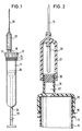
- eine schematische Seitenansicht eines erfindungsgemäßen Flüssigkeitsaufbewahrungsbehälters in Form einer Blutabnahmevorrichtung in Gebrauchsstellung noch ohne aufgesetzte Verschlußkappe,
- Fig. 2
- eine vergrößerte Schnittansicht des vorderen Teils des Flüssigkeitsaufbewahrungsbehälters nach Fig. 1,
- Fig. 3
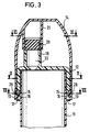
- eine Schnittansicht analog Fig. 2, wobei jedoch die Führungshülse mit der Kanüle abgenommen und stattdessen eine erfindungsgemäße Verschlußkappe mit Rastring auf das vordere Ende des Röhrchens aufgesetzt ist,
- Fig. 4
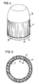
- eine schematische perspektivische Ansicht der erfindungsgemäßen Verschlußkappe mit Rastring,
- Fig. 5
- einen schematischen Schnitt nach Linie V-V in Fig. 3,
- Fig. 6
- einen Schnitt nach Linie VI-VI in Fig. 3, und
- Fig. 7
- einen Schnitt nach Linie VII-VII in Fig. 3.
- Fig. 1
- FIG. 2 shows a schematic side view of a liquid storage container according to the invention in the form of a blood collection device in the position of use, without a cap,
- Fig. 2
- 2 is an enlarged sectional view of the front part of the liquid storage container shown in FIG. 1;
- Fig. 3
- 3 shows a sectional view analogous to FIG. 2, but with the guide sleeve removed with the cannula and instead a closure cap according to the invention with a locking ring being placed on the front end of the tube,
- Fig. 4
- 2 shows a schematic perspective view of the closure cap according to the invention with locking ring,
- Fig. 5
- 3 shows a schematic section along line VV in FIG. 3,
- Fig. 6
- a section along line VI-VI in Fig. 3, and
- Fig. 7
- a section along line VII-VII in Fig. 3rd
In allen Figuren der Zeichnung bezeichnen gleiche Bezugszahlen einander entsprechende Bauteile.In all figures of the drawing, the same reference numbers designate corresponding components.
Nach den Fig. 1 und 2 erstreckt sich durch das abgerundete und mit einer Durchtrittsöffnung versehene hintere Ende 24 eines aus Kunststoff bestehenden kreiszylindrischen Röhrchens 11 gleitend eine Kolbenstange 25, die an ihrem vorderen Ende einen axial gleitend im Innern des Röhrchens 11 angeordneten Kolben 26 trägt. Auf das mit einem Außengewinde versehene vordere Ende des Röhrchens 11 ist eine Schraubkappe 12 aufgeschraubt, welche einen axial nach vorn vorstehenden kreiszylindrischen Ansatz 18 einstückig trägt, in dem ein axialer Durchgangskanal 22 vorgesehen ist, der wiederum an seinem vorderen Ende durch ein elastisches Verschlußglied 20 verschlossen ist.1 and 2 extends through the rounded and provided with a through opening
Auf den Ansatz 18 ist von vorn eine Führungshülse 27 aufgeschoben, die eine kreiszylindrische und zum Ansatz 18 komplementäre Innenfläche aufweist. Die Führungshülse 27 ist an ihrem rückwärtigen Ende offen und am vorderen Ende verschlossen. Dort wird sie von einer an ihr befestigten Kanüle 19 durchgriffen, die an beiden Enden angeschärft ist. Das rückwärtige Ende ist von einem elastischen Schlauch 28 überzogen.A
Wird die Führungshülse 27 aus der Position nach Fig. 2 weiter auf den Ansatz 18 aufgeschoben, so durchbohrt das rückwärtige Ende der Kanüle 19 zunächst den elastischen Schlauch 28 und dann den Verschlußstopfen 20, den sie schließlich vollständig durchdringt, um in den Durchgangskanal 22 zu münden. Der Schlauch 28 schiebt sich dabei ziehharmonikaartig zusammen. Nunmehr kann mit der gezeigten Anordnung Blut aus der Vene eines Patienten entnommen werden, in die die Kanüle 19 eingestochen ist. Hierbei wird der Kolben 26 zurückgezogen.If the
Soweit, wie bisher beschrieben, ist der zur Blutentnahme dienende Flüssigkeitsaufnahmebehälter aus der DE-PS 29 48 653 bekannt.As far as described so far, the liquid container used for taking blood is known from DE-PS 29 48 653.
Erfindungsgemäß ist nach Fig. 2 an der Außenwand des Röhrchens 11 unmittelbar hinter der aufgeschraubten Schraubkappe 12 ein einstückiger Ringvorsprung 15 vorgesehen, der koaxial mit dem Röhrchen 11 ist. In geringem Abstand dahinter befindet sich ein ebenfalls zum Röhrchen 11 koaxialer Abdeckring 17.According to the invention is according to Fig. 2 on the outer wall of the
Nach der Blutentnahme wird die Führungshülse 27 nach vorn abgezogen, worauf eine in Fig. 4 dargestellte Verschlußkappe 14 mit einem an ihrem offenen Ende über Sollbruchstellen 29 angeordneten Rastring 13 gemäß Fig. 3 von vorn auf das mit der Schraubkappe 12 versehene Röhrchen 11 aufgeschoben wird. Der Rastring 13 weist gemäß den Fig. 3 und 7 radial innen über den Umfang verteilt vier Rastvorsprünge 16 auf, die hinten zum Auflaufen auf den Ringvorsprung 15 abgeschrägt, vorn dagegen flach ausgebildet sind, damit sie nach dem zwanglosen Aufschnappen auf den Ringvorsprung 15 axial nicht mehr nach vorn über den Ringvorsprung 15 abgezogen werden können.After the blood has been drawn, the
Der Innenumfang des Rastringes 13 ist so ausgebildet, daß er von vorn axial über den Ringvorsprung 15 paßt, so daß die schrägen Rückenflächen der Rastvorsprünge 16 auf den Ringvorsprung 15 aufgleiten und unter federnder Erweiterung des Rastringes 13 schließlich hinter den Ringvorsprung 15 schnappen können.The inner circumference of the locking
Der Innendurchmesser des rückwärtigen Endes der Verschlußkappe entspricht dem Außendurchmesser der Schraubkappe 12, so daß der rückwärtige Teil der Verschlußkappe 14 formschlüssig auf dem Außenumfang der Schraubkappe 12 aufliegt, welche nach den Fig. 4 und 5 außen mit einer Riffelung versehen ist, die aus axialen Rippen 23 besteht. Innen ist die Verschlußkappe 14 mit einer komplementären Oberflächenprofilierung 30 versehen, so daß bei gemäß Fig. 3 aufgesetzter Verschlußkappe 14 zwischen dieser und der Schraubkappe 12 eine drehfeste formschlüssige Verbindung vorliegt. Vorzugsweise verjüngt sich die Verschlußkappe 14 oberhalb der Schraubkappe 12 derart, daß ein wesentlich weiteres axiales Aufschieben der Verschlußkappe 14 auf die Schraubkappe 12, als es in Fig. 3 dargestellt ist, nicht möglich ist.The inside diameter of the rear end of the sealing cap corresponds to the outside diameter of the
Der hintere Rand der Verschlußkappe 14 schließt vorzugsweise in etwa bündig mit dem hinteren Rand der Schraubkappe 12 ab. Der Rastring 13 befindet sich unmittelbar hinter der Schraubkappe 12.The rear edge of the
Die axiale Ausdehnung des Rastringes 13 ist gemäß Fig. 3 derart, daß er sich bei aufgesetzter Verschlußkappe 14 nur etwa bis zum Abdeckring 17 erstreckt. Der Außendurchmesser des Abdeckringes 17 ist geringfügig größer als der Innendurchmesser des Rastringes 13 am hinteren Ende, so daß nach dem in Fig. 3 dargestellten Aufschnappen des Rastringes 13 auf den Ringvorsprung 15 eine weitere axiale Verschiebung des Rastringes 13 und damit der Verschlußkappe 14 nach hinten nicht möglich ist. Auf diese Weise ist die Position der Verschlußkappe 14 auf dem Röhrchen 11 eindeutig definiert.The axial extent of the locking
An der vorderen Innenseite weist die Verschlußkappe 14 nach den Fig. 3 und 6 einen sich von der Vorderwand nach hinten axial erstreckenden Kappenvorsprung 21 auf, der einstückig an die vorzugsweise aus Kunststoff bestehende Verschlußkappe 14 mit angeformt ist und koaxial zum Ansatz 18 verläuft. Bei aufgesetzter Verschlußkappe 14 setzt sich der vorzugsweise kreiszylindrisch ausgebildete hohle Kappenvorsprung 21 in der aus den Fig. 3 und 6 ersichtlichen Weise axial auf den Ansatz 18 und verschließt diesen damit gegen ein unkontrolliertes Auslaufen von Blut, welches an der Vorderfläche des elastischen Verschlußgliedes 20 vorhanden sein könnte.3 and 6 on the front inner side has a
Erfindungsgemäß ist die Verschlußkappe auch auf ihrem. Außenumfang mit einer Riffelung 31 versehen, wie das in den Fig. 4 und 6 angedeutet ist.According to the closure cap is also on your. Provided outer circumference with a
Die Arbeitsweise des beschriebenen Flüssigkeitsaufnahmebehälters ist wie folgt:
Nach einer Blutentnahme wird die Führungshülse 27 (Fig. 2) abgezogen und entweder in der Vene des Patienten gelassen oder weggeworfen.The method of operation of the described liquid holding container is as follows:
After blood is drawn, the guide sleeve 27 (FIG. 2) is withdrawn and either left in the patient's vein or thrown away.
Auf das vordere Ende des von der Führungshülse 27 entblößten Flüssigkeitsbehälters wird dann gemäß Fig. 3 die aus Fig. 4 ersichtliche Verschlußkappe von vorn aufgeschoben, wobei die Rastvorsprünge 16 unter geringfügiger federnder Erweiterung des hinteren zylindrischen Teils der Verschlußkappe 14 am Außenumfang der Schraubkappe 12 entlanggleiten, bis sie schließlich hinter den Ringvorsprung 15 schnappen. Dabei setzt sich der Kappenvorsprung 21 dichtend oder zumindest das unkontrollierte Auslaufen von Blut verhindernd auf den Ansatz 18. In der aus Fig. 3 ersichtlichen Position kann der Flüssigkeitsaufnahmebehälter nunmehr zum Versand gebracht werden.3, the closure cap shown in FIG. 4 is then pushed onto the front end of the liquid container bared by the
In dem Labor, wo der Inhalt des Röhrchens 11 untersucht werden soll, wird nunmehr die Schraubkappe 12 dadurch abgeschraubt, daß die Verschlußkappe 14 in Höhe der Schraubkappe 12 mit zwei Fingern ergriffen und entgegen dem Uhrzeigersinn gedreht wird. Hierbei wird das auf die Verschlußkappe 14 ausgeübte Drehmoment auf die Schraubkappe 12 übertragen und diese axial vom Röhrchen 11 entfernt. Da die Rastvorsprünge 16 axial unlösbar hinter den Ringvorsprung 15 greifen, brechen bei dem Abschraubvorgang die Sollbruchstellen 29 auf, und die Verschlußkappe 14 wird vom Rastring 13 getrennt, welcher aufgrund der beschriebenen baulichen Ausbildung zwischen dem Ringvorsprung 15 und dem Abdeckring 17 festgehalten bleibt.In the laboratory, where the content of the
Nach dem Abnehmen der Verschlußkappe 14 mit der Schraubkappe 12 kann der Inhalt des Röhrchens 11 entnommen werden.After removing the
Sollte die Schraubkappe 12 zwischenzeitlich entfernt und wieder aufgesetzt worden sein, so erkennt man dies ohne weiteres an der erfolgten Zerstörung der Sollbruchstellen 29.If the
Eine Abnahme der Verschlußkappe 14 ist auch nicht dadurch möglich, daß von hinten ein Werkzeug hinter den Rastring 13 geführt wird, weil dies durch den mit dem Röhrchen 11 einstückigen Abdeckring 17 verhindert wird.A removal of the
Erfindungsgemäß kann der Kappenvorsprung 21 auch so ausgebildet werden, daß er auf einen üblichen Kanülenkonus an der Vorderseite der Schraubkappe 12 dichtend aufgesetzt werden kann. Hierzu wäre der Kappenvorsprung 21 komplementär zur Außenform des Kanülenansatzes auszubilden.According to the invention, the
Claims (8)
- Fluid-storing container, especially for body fluids and/or for transporting fluids from a filling site to an examination site, having a preferably cylindrical tube (11) which is open at one end and is closed in a fluid-tight manner by a closure element (12) which can be removed for introducing or removing fluid and is provided at the front end of the tube, and having a closure cap (14) which can be placed on the front end of the tube, characterised in that a locking means (15) is provided behind the fitted closure element (12) on the outer wall of the tube (11) and the closure cap (14) is provided with a tear-off locking ring (13) at its open end and can be placed on the front end of the tube (11) in such a manner that the locking ring (13) snaps over the locking means (15), whereupon the closure cap (14) covers the closure element (12) from the outside in such a manner that it is not possible to open the closure element (12) without separating the locking ring (13) from the closure cap (14).
- Container according to claim 1, characterised in that the locking means comprises an annular projection (15) which is provided around the tube (11) and is preferably integral with the tube (11).
- Container according to claim 1 or 2, characterized in that the locking ring (13) carries locking protuberances (16) which are distributed radially on the inside over the circumference and which are in locking engagement with the locking means (15).
- Container according to any one of the preceding claims, characterized in that a cover ring (17) is provided on the outer wall of the tube (11) at a distance behind the locking means (15) and covers the locking ring (13) and the locking means (15) against manipulation from outside when the closure cap (14) has been fitted and the locking ring (13) has not been torn off.
- Container according to any one of the preceding claims, characterized in that a preferably cylindrical attachment (18) which projects forwards from the closure element (12) and has an axial through channel (22) is provided which accommodates a closure member (20) which can be perforated by the rear end of a cannula (19) which is sharpened at both ends and in that the closure cap (14) has, on the inside, a cap projection (21) which covers the front end of the attachment (18) and closes it in a sealing manner when the closure cap (14) has been fitted.
- Container according to either of claims 4 and 5, characterised in that a surface profiling (23) is provided on the outer circumference of the screw cap (12) and the closure cap (14) has a complementary surface profiling (30) on its inner circumference which corresponds in diameter to the outside diameter of the screw cap (12), in such a manner that the fitted closure cap (14) is connected to the screw cap (12) in a rotationally secure manner and at least in non-positively locking manner but preferably in positively locking manner.
- Combination of a closure element (12) and a closure cap (14) for a fluid-storing container, especially for body fluids and/or for transporting fluids from a filling site to an examination site, having a preferably cylindrical tube (11) which is open at one end and is closed in a fluid-tight manner by the closure element (12) which can be removed for introducing and removing fluid and is provided at the front end of the tube (11), and having a closure cap (14) fitted on the front end of the tube, characterised in that the closure cap (14) is provided with a tear-off locking ring (13) at its open end and is so arranged on the closure element (12) in a manner covering that closure element from the outside that the tear-off locking ring (13) of the closure cap (14) is located immediately behind the rear edge of the closure element (12).
- Method of securing fluid-storing containers against unauthorised opening, characterised in that a container according to any one of claims 1 to 6 is provided, the tube (11) is filled with a fluid that is to be stored and/or transported and the closure cap (14) with the locking ring (13) is snapped axially onto the closed front end of the tube (11) by hand.
Applications Claiming Priority (2)
| Application Number | Priority Date | Filing Date | Title |
|---|---|---|---|
| DE3818115 | 1988-05-27 | ||
| DE3818115A DE3818115C2 (en) | 1988-05-27 | 1988-05-27 | Cap for liquid storage containers and their application to the front end of the container |
Publications (3)
| Publication Number | Publication Date |
|---|---|
| EP0343534A2 EP0343534A2 (en) | 1989-11-29 |
| EP0343534A3 EP0343534A3 (en) | 1990-11-28 |
| EP0343534B1 true EP0343534B1 (en) | 1995-11-29 |
Family
ID=6355291
Family Applications (1)
| Application Number | Title | Priority Date | Filing Date |
|---|---|---|---|
| EP89109066A Expired - Lifetime EP0343534B1 (en) | 1988-05-27 | 1989-05-19 | Container for preserving liquids, in particular bodily liquids |
Country Status (3)
| Country | Link |
|---|---|
| US (1) | US4940154A (en) |
| EP (1) | EP0343534B1 (en) |
| DE (2) | DE3818115C2 (en) |
Families Citing this family (3)
| Publication number | Priority date | Publication date | Assignee | Title |
|---|---|---|---|---|
| SE504659C2 (en) * | 1995-07-03 | 1997-03-24 | Althin Medical Ab | Screw cap with powder cartridge valve for dialysis machine |
| US6491667B1 (en) * | 1999-08-31 | 2002-12-10 | Becton, Dickinson And Company | Syringe tip cap |
| US20060018799A1 (en) * | 2004-07-21 | 2006-01-26 | Wong Cai Ne W | Universal tissue homogenizer device and methods |
Family Cites Families (20)
| Publication number | Priority date | Publication date | Assignee | Title |
|---|---|---|---|---|
| US3455478A (en) * | 1967-07-21 | 1969-07-15 | Roehr Metals & Plastics Co | Tamper-indicating closure |
| GB1244694A (en) * | 1969-06-04 | 1971-09-02 | Johnsen Jorgensen Plastics Ltd | Improvements in and relating to containers and closures therefor |
| US3480172A (en) * | 1968-04-09 | 1969-11-25 | Baxter Laboratories Inc | Reclosed package |
| US3737064A (en) * | 1971-05-17 | 1973-06-05 | C Patel | Pilfer-proof closure for containers |
| GB1438648A (en) * | 1972-11-10 | 1976-06-09 | Metal Box Co Ltd | Closures for containers |
| BE802220A (en) * | 1973-07-16 | 1973-11-05 | Astra Plastique | DOUBLE STOPPER CLOSURE FOR VIALS, BOTTLES AND SIMILAR CONTAINERS |
| DE2533256C3 (en) * | 1974-11-29 | 1978-04-20 | Walter Sarstedt Kunststoff-Spritzgusswerk, 5223 Nuembrecht | Blood collection device |
| DE2948653C2 (en) * | 1979-12-04 | 1984-01-05 | Walter Sarstedt Kunststoff-Spritzgußwerk, 5223 Nümbrecht | Blood collection device |
| FR2499519A1 (en) * | 1981-02-11 | 1982-08-13 | Grussen Jean | SCREW CAPSULE WITH INVIOLABILITY RING |
| GB2096584B (en) * | 1981-03-31 | 1985-04-11 | Ug Closures & Plastics Ltd | Plastics closure |
| FR2507160A1 (en) * | 1981-06-05 | 1982-12-10 | Barre Rene | CLOSING DEVICE FOR BOTTLES |
| AU552883B2 (en) * | 1981-11-03 | 1986-06-26 | Walter Sarstedt Kunststoff-Spritzgusswerk | Blood extracting and centrifuging device |
| US4592475A (en) * | 1982-12-06 | 1986-06-03 | Charles N. Hannon | Plastic closure with mechanical pilfer-proof |
| DE3336908A1 (en) * | 1983-10-11 | 1985-04-18 | Zeller Plastik Koehn, Gräbner & Co, 5583 Zell | ORIGINAL LOCKING PLASTIC |
| WO1993012983A1 (en) * | 1984-06-19 | 1993-07-08 | Seikuro Yasada | Combination of container and cap |
| US4784281A (en) * | 1984-12-10 | 1988-11-15 | Oleg Rozenberg | Tamper-evident closures |
| DE3505892A1 (en) * | 1985-02-20 | 1986-08-21 | GVB SANIMED Hygiene- und Medizintechnik GmbH, 3070 Nienburg | Closable container for receiving laboratory samples, hazardous waste or the like |
| IT1187212B (en) * | 1985-11-07 | 1987-12-16 | Bormioli Metalplast Spa | LID OF THE CHILD PROOF TYPE WITH INVIOLABILITY CLAMP |
| PT86049A (en) * | 1986-11-06 | 1988-12-15 | Astra Plastique | COVER FOR INITIALLY CLOSED CONTAINER WITH PERFURABLE OPCULTURE |
| US4736859A (en) * | 1987-02-10 | 1988-04-12 | Helena Laboratories Corporation | Container and non-removable cover |
-
1988
- 1988-05-27 DE DE3818115A patent/DE3818115C2/en not_active Expired - Fee Related
-
1989
- 1989-05-19 EP EP89109066A patent/EP0343534B1/en not_active Expired - Lifetime
- 1989-05-19 DE DE58909510T patent/DE58909510D1/en not_active Expired - Fee Related
- 1989-05-26 US US07/363,669 patent/US4940154A/en not_active Expired - Lifetime
Also Published As
| Publication number | Publication date |
|---|---|
| EP0343534A2 (en) | 1989-11-29 |
| US4940154A (en) | 1990-07-10 |
| DE3818115A1 (en) | 1989-11-30 |
| DE3818115C2 (en) | 1997-09-25 |
| EP0343534A3 (en) | 1990-11-28 |
| DE58909510D1 (en) | 1996-01-11 |
Similar Documents
| Publication | Publication Date | Title |
|---|---|---|
| EP0808148B1 (en) | Transfer device | |
| DE2948653C2 (en) | Blood collection device | |
| DE69515885T2 (en) | Containers for pharmaceutical products with two separate components, with means for mixing and dispensing them and methods for assembling the container | |
| DE69312366T2 (en) | Liquid container | |
| DE3873178T2 (en) | LOCKING DEVICE FOR CONTAINERS. | |
| DE102012113002B4 (en) | Transfer device for removing or transferring a fluid | |
| EP0788804A2 (en) | Medical applicator | |
| DE69808205T2 (en) | Device for filling and administering syringes | |
| DE1098167B (en) | Container with a hypodermic needle | |
| EP0679380A1 (en) | Device for transferring and dispensing of fluids out of bottles, bags or similar containers for medical purposes | |
| DE19956243A1 (en) | Tip cap unit for a syringe cylinder comprises inner and outer caps and a sleeve interacting in such a way that the inner cap can be removed only after the outer cap has been removed | |
| EP1406686A1 (en) | Device for distributing substances | |
| EP0766955A1 (en) | Port system for a bag | |
| DE29607437U1 (en) | Medical device | |
| EP3233016B1 (en) | Connector system comprising at least two outlet ports | |
| DE69030117T2 (en) | UNIT DOSE CONTAINER | |
| EP0343534B1 (en) | Container for preserving liquids, in particular bodily liquids | |
| DE19647978A1 (en) | Device for taking blood samples | |
| DE69228048T2 (en) | WITHDRAWN SYRINGE | |
| EP0643944B1 (en) | Blood sampling device | |
| EP1438924B1 (en) | Waste container | |
| EP0766956A1 (en) | Container for medical liquid | |
| DE2208704A1 (en) | Safe and reusable sterile locking device against adulteration or contamination | |
| WO1997036624A1 (en) | Syringe for medicinal purposes | |
| EP0534136B1 (en) | Closure with protective cap |
Legal Events
| Date | Code | Title | Description |
|---|---|---|---|
| PUAI | Public reference made under article 153(3) epc to a published international application that has entered the european phase |
Free format text: ORIGINAL CODE: 0009012 |
|
| AK | Designated contracting states |
Kind code of ref document: A2 Designated state(s): DE FR GB IT |
|
| PUAL | Search report despatched |
Free format text: ORIGINAL CODE: 0009013 |
|
| AK | Designated contracting states |
Kind code of ref document: A3 Designated state(s): DE FR GB IT |
|
| RHK1 | Main classification (correction) |
Ipc: A61B 5/14 |
|
| 17P | Request for examination filed |
Effective date: 19910527 |
|
| 17Q | First examination report despatched |
Effective date: 19930614 |
|
| GRAA | (expected) grant |
Free format text: ORIGINAL CODE: 0009210 |
|
| AK | Designated contracting states |
Kind code of ref document: B1 Designated state(s): DE FR GB IT |
|
| ITF | It: translation for a ep patent filed | ||
| REF | Corresponds to: |
Ref document number: 58909510 Country of ref document: DE Date of ref document: 19960111 |
|
| ET | Fr: translation filed | ||
| GBT | Gb: translation of ep patent filed (gb section 77(6)(a)/1977) |
Effective date: 19960305 |
|
| PLBE | No opposition filed within time limit |
Free format text: ORIGINAL CODE: 0009261 |
|
| STAA | Information on the status of an ep patent application or granted ep patent |
Free format text: STATUS: NO OPPOSITION FILED WITHIN TIME LIMIT |
|
| 26N | No opposition filed | ||
| REG | Reference to a national code |
Ref country code: GB Ref legal event code: IF02 |
|
| PGFP | Annual fee paid to national office [announced via postgrant information from national office to epo] |
Ref country code: DE Payment date: 20040426 Year of fee payment: 16 |
|
| PGFP | Annual fee paid to national office [announced via postgrant information from national office to epo] |
Ref country code: FR Payment date: 20040510 Year of fee payment: 16 |
|
| PGFP | Annual fee paid to national office [announced via postgrant information from national office to epo] |
Ref country code: GB Payment date: 20040519 Year of fee payment: 16 |
|
| PG25 | Lapsed in a contracting state [announced via postgrant information from national office to epo] |
Ref country code: IT Free format text: LAPSE BECAUSE OF NON-PAYMENT OF DUE FEES;WARNING: LAPSES OF ITALIAN PATENTS WITH EFFECTIVE DATE BEFORE 2007 MAY HAVE OCCURRED AT ANY TIME BEFORE 2007. THE CORRECT EFFECTIVE DATE MAY BE DIFFERENT FROM THE ONE RECORDED. Effective date: 20050519 Ref country code: GB Free format text: LAPSE BECAUSE OF NON-PAYMENT OF DUE FEES Effective date: 20050519 |
|
| PG25 | Lapsed in a contracting state [announced via postgrant information from national office to epo] |
Ref country code: DE Free format text: LAPSE BECAUSE OF NON-PAYMENT OF DUE FEES Effective date: 20051201 |
|
| GBPC | Gb: european patent ceased through non-payment of renewal fee |
Effective date: 20050519 |
|
| PG25 | Lapsed in a contracting state [announced via postgrant information from national office to epo] |
Ref country code: FR Free format text: LAPSE BECAUSE OF NON-PAYMENT OF DUE FEES Effective date: 20060131 |
|
| REG | Reference to a national code |
Ref country code: FR Ref legal event code: ST Effective date: 20060131 |