EP0343484A2 - Commutateur de proximité sans contact pour installations de chemin de fer - Google Patents
Commutateur de proximité sans contact pour installations de chemin de fer Download PDFInfo
- Publication number
- EP0343484A2 EP0343484A2 EP89108777A EP89108777A EP0343484A2 EP 0343484 A2 EP0343484 A2 EP 0343484A2 EP 89108777 A EP89108777 A EP 89108777A EP 89108777 A EP89108777 A EP 89108777A EP 0343484 A2 EP0343484 A2 EP 0343484A2
- Authority
- EP
- European Patent Office
- Prior art keywords
- proximity switch
- sensor
- resistor
- voltage
- wire line
- Prior art date
- Legal status (The legal status is an assumption and is not a legal conclusion. Google has not performed a legal analysis and makes no representation as to the accuracy of the status listed.)
- Granted
Links
Images

Classifications
-
- H—ELECTRICITY
- H03—ELECTRONIC CIRCUITRY
- H03K—PULSE TECHNIQUE
- H03K17/00—Electronic switching or gating, i.e. not by contact-making and –breaking
- H03K17/26—Modifications for temporary blocking after receipt of control pulses
-
- B—PERFORMING OPERATIONS; TRANSPORTING
- B61—RAILWAYS
- B61L—GUIDING RAILWAY TRAFFIC; ENSURING THE SAFETY OF RAILWAY TRAFFIC
- B61L1/00—Devices along the route controlled by interaction with the vehicle or train
- B61L1/02—Electric devices associated with track, e.g. rail contacts
- B61L1/10—Electric devices associated with track, e.g. rail contacts actuated by electromagnetic radiation; actuated by particle radiation
-
- H—ELECTRICITY
- H03—ELECTRONIC CIRCUITRY
- H03K—PULSE TECHNIQUE
- H03K17/00—Electronic switching or gating, i.e. not by contact-making and –breaking
- H03K17/94—Electronic switching or gating, i.e. not by contact-making and –breaking characterised by the way in which the control signals are generated
- H03K17/945—Proximity switches
-
- H—ELECTRICITY
- H03—ELECTRONIC CIRCUITRY
- H03K—PULSE TECHNIQUE
- H03K5/00—Manipulating of pulses not covered by one of the other main groups of this subclass
- H03K5/01—Shaping pulses
- H03K5/04—Shaping pulses by increasing duration; by decreasing duration
Definitions
- the invention relates to a non-contact proximity switch with a sensor which can be remotely fed via a two-wire line and whose electrical properties can be influenced by metal parts, the sensor voltage, which can be changed when influenced, controls an electronic threshold switch, which is also connected to the two-wire line and acknowledges any influence with a change in current consumption.
- Such devices are used as rail contacts for triggering pulses when passing vehicle wheels.
- the impulses control counting devices that are housed on the line or in signal boxes together with other railway signaling equipment. After counting in a first pulse from a sensor device that controls this counting device and is arranged at the beginning of the track section in question, a busy message is output by the counting device.
- a further sensor device arranged in the direction of travel at the end of the said track section gives counting pulses to the counting device when passing vehicle wheels, such that the track section is released again after counting all the counted pulses.
- two sensor devices are arranged close to one another on the track, which for safety reasons are connected to the remote device via two two-wire lines.
- This device also ensures the energy supply of the assigned sensor devices. Since the current consumption on the two-wire line changes when the sensor devices are actuated by triggering the respective electronic threshold switch, the required counting pulses can be generated centrally on the basis of an evaluation of the supply currents.
- a window discriminator can be provided, for example, which does not have a predetermined operating current on the two-wire line Output signal, but in the event of deviations in the current by a predetermined amount from the operating current triggers a related pulse. It is also possible to insert an ohmic measuring resistor between the two-wire line in the center located away from the contactless proximity switch, at which the supply current causes a predetermined voltage drop, which is evaluated by a threshold switch for the purpose of triggering the counting pulses.
- a contactless proximity switch of the type mentioned is described in DE-OS 33 27 329 as an electronic, preferably contactlessly operating switching device. It is to be used instead of electrical, mechanically operated switching devices in measuring, control and regulating circuits.
- proximity switches are used in the rough field of railway safety, they have to meet special time conditions. In order to trigger pulses at higher driving speeds that do not fall short of a specified time, special circuitry measures are required. These measures generally lead to an undesirable increase in the current consumption of the proximity switch, which, however, is undesirable or not permitted for various reasons.
- the invention has for its object to improve a non-contact proximity switch of the type mentioned so that even short-term influences of high-speed trains trigger pulses that do not fall below a predetermined duration.
- the readiness for recovery after a pulse is given should be as short as possible so that all wheels of a rapidly passing train can be detected with certainty.
- the object is achieved in that an operational amplifier is provided as the threshold value switch, the measuring input of which is supplied with the sensor voltage, the reference input of which is connected to the output of the operational amplifier via a first resistor with a reference voltage source and via a second resistor in series with a first diode.
- a non-contact proximity switch allows an exact pulse extension with regard to pulses from vehicle wheels passing at high speed with little expenditure of electricity and components. Furthermore, it is particularly advantageous that the proximity switch according to the invention requires a particularly short readiness period after a pulse has been given, so that wheel influences can be reported in a particularly rapid sequence in a correct manner.
- the arrangement according to FIG. 1 shows a contactless proximity switch which transmits information to a stationary station SN via a two-wire line ZL.
- the proximity switch is also supplied with energy from a battery UB via the same two-wire line ZL. Due to a modulation process of the sensor current IS by influencing processes of the contactless proximity switch, these are reported to the fixed station SN. For this purpose, a voltage that can be removed at the series resistor RV and at the terminals Kl and K2 can be evaluated.
- the remote-fed proximity switch connected to the two-wire line ZL essentially consists of two assemblies, namely the actual sensor SR and an electronic threshold switch controllable by the sensor voltage US emitted by the sensor SR. Both the sensor SR and the electronic threshold switch, which contains an operational amplifier OP as an active element, are supplied remotely via the two-wire line ZL. It is essential for operational reasons that the current consumption of the contactless proximity switch is low, especially in the state of an interference signal.
- the sensor SR is deliberately shown only as a symbol, because its electronic structure can be of any type. It is essential that when used in railway signaling with appropriate mounting on the track due to passing vehicle wheels, its electrical behavior changes in such a way that a sensor voltage is generated with each influence, the amplitude of which is sufficiently different from that which is present when the sensor SR is not influenced.
- the electronic threshold switch with the operational amplifier OP whose measurement input MOP is connected to the output of the sensor SR carrying the sensor voltage US, is used to evaluate the sensor voltage US.
- the operational amplifier OP is supplied via its reference input ROP and a resistor R1 with the reference voltage UREF of a voltage stabilization circuit consisting of a resistor R0 and a Zener diode Z1 and connected to the two-wire line ZL.
- the reference input ROP is connected via a resistor R2 in series with a diode D1 to the output AOP of the operational amplifier OP. This feedback results in a hysteresis in the switching behavior of the operational amplifier OP.
- the output AOP of the operational amplifier OP which is preferably equipped with an open collector output, is connected via a resistor R3 to one of the two lines of the two-wire line ZL and via the series connection of a capacitor C1 and a further resistor R4 to the other line.
- the at the resistor R4 given predetermined charging processes of the capacitor Cl dropping voltages are additionally supplied as control voltage UST to the reference input ROP of the operational amplifier OP via a diode D2.
- a diode D3 connected in parallel with the resistor R4 has the task of preventing the potential arising at the reference input ROP from operating after each influencing of the sensor SR from reaching the negative battery voltage.
- Zener diode Z2 which is connected in parallel to the two diodes D2 and D3, has the task of limiting the sum voltage generated at the reference input ROP of the operational amplifier OP by superimposing the reference voltage UREF and the control voltage UST to a predetermined value.
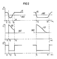
- FIG. 2 shows signal profiles that are present when the sensor SR is influenced for a very short time or for a longer period.
- the reference voltage UREF and the sensor voltage US are plotted as a function of the time t.
- the middle diagram shows the course of the control voltage UST in connection with the reference voltage UREF, while the lower diagram of FIG. 2 shows the sensor current IS as a function of the time t.
- time t1 there may be no influence on sensor SR, so that its sensor voltage US is greater than the reference voltage UREF.
- the output AOP of the operational amplifier OP is at a low potential.
- the capacitor C1 is discharged.
- sensor voltage US drops below the value of reference voltage UREF due to influencing sensor SR, so that the output transistor (not shown) of operational amplifier OP blocks.
- the potential at the AOP output changes from low to high potential.
- the sensor current IS is reduced on the two-wire line ZL, as can be seen in the lower diagram line.
- the suddenly increasing control voltage UST, cf. the course after the time t2 in the middle diagram line the Reference voltage UREF superimposed.
- the operational amplifier OP does not switch to the basic position at the time t3, at which the influencing has approximately ended again, but only for a time later, namely at the time t4.
- the capacitor C1 is discharged with a low resistance.
- the courses shown in the right part of the three diagram lines in FIG. 2 are assigned to a slow influencing process.
- This begins at time t5 and is ended at time t6 after a duration that is substantially greater than the duration between times t2 and t3.
- the control voltage UST has already decayed again, so that the switching behavior of the operational amplifier OP is determined solely by the reference voltage UREF.
- the capacitor C1 is discharged again with a low resistance after the time t6 through the output transistor of the operational amplifier OP, the voltage jump occurring at the resistor R4 being kept away from the reference input ROP by the diode D2, as in processes with short influencing periods.
- the circuit of the contactless proximity switch according to the invention performs a pulse extension depending on the influencing duration with an always very short readiness period after any influencing, and only for those pulses which are due to very short-lasting loading influences are triggered and could lead to incorrect controls in the fixed station SN.
Landscapes
- Physics & Mathematics (AREA)
- Engineering & Computer Science (AREA)
- Nonlinear Science (AREA)
- Electromagnetism (AREA)
- Automation & Control Theory (AREA)
- Mechanical Engineering (AREA)
- Electronic Switches (AREA)
- Switches That Are Operated By Magnetic Or Electric Fields (AREA)
- Keying Circuit Devices (AREA)
Priority Applications (1)
| Application Number | Priority Date | Filing Date | Title |
|---|---|---|---|
| AT89108777T ATE96258T1 (de) | 1988-05-27 | 1989-05-16 | Beruehrungsloser naeherungsschalter fuer eisenbahnanlagen. |
Applications Claiming Priority (2)
| Application Number | Priority Date | Filing Date | Title |
|---|---|---|---|
| DE3818090 | 1988-05-27 | ||
| DE3818090 | 1988-05-27 |
Publications (3)
| Publication Number | Publication Date |
|---|---|
| EP0343484A2 true EP0343484A2 (fr) | 1989-11-29 |
| EP0343484A3 EP0343484A3 (fr) | 1991-02-27 |
| EP0343484B1 EP0343484B1 (fr) | 1993-10-20 |
Family
ID=6355285
Family Applications (1)
| Application Number | Title | Priority Date | Filing Date |
|---|---|---|---|
| EP89108777A Expired - Lifetime EP0343484B1 (fr) | 1988-05-27 | 1989-05-16 | Commutateur de proximité sans contact pour installations de chemin de fer |
Country Status (3)
| Country | Link |
|---|---|
| EP (1) | EP0343484B1 (fr) |
| AT (1) | ATE96258T1 (fr) |
| DE (1) | DE58905939D1 (fr) |
Family Cites Families (5)
| Publication number | Priority date | Publication date | Assignee | Title |
|---|---|---|---|---|
| FR1415756A (fr) * | 1964-09-16 | 1965-10-29 | Werk Signal Sicherungstech Veb | Dispositif pour prolonger la durée de contact d'une pièce de contact actionnée directement par une impulsion de flux magnétique |
| US3562603A (en) * | 1968-10-30 | 1971-02-09 | Gen Signal Corp | Magnetic reed proximity detector |
| DE2257373B1 (de) * | 1972-11-23 | 1973-10-11 | Sds-Elektro Gmbh, 8024 Deisenhofen | Schaltungsanordnung zur Ver zogerung des Anzugs eines Relais |
| US4344071A (en) * | 1980-07-10 | 1982-08-10 | Roger A. Heller | Light switching mechanism |
| DE3643970A1 (de) * | 1986-12-22 | 1988-06-30 | Siemens Ag | Sensoreinrichtung fuer eisenbahnanlagen |
-
1989
- 1989-05-16 EP EP89108777A patent/EP0343484B1/fr not_active Expired - Lifetime
- 1989-05-16 DE DE89108777T patent/DE58905939D1/de not_active Expired - Fee Related
- 1989-05-16 AT AT89108777T patent/ATE96258T1/de not_active IP Right Cessation
Also Published As
| Publication number | Publication date |
|---|---|
| EP0343484B1 (fr) | 1993-10-20 |
| EP0343484A3 (fr) | 1991-02-27 |
| ATE96258T1 (de) | 1993-11-15 |
| DE58905939D1 (de) | 1993-11-25 |
Similar Documents
| Publication | Publication Date | Title |
|---|---|---|
| DE1945420C3 (de) | Digitales Integrations-Synchronisations-Schaltnetzwerk | |
| DE2442066B2 (de) | Verfahren und Schaltungsanordnung zur Fernsteuerung elektrischer Geräte | |
| DE3218541C1 (de) | Schienenkontakt für spurgeführte Fahrzeuge | |
| EP0089048B1 (fr) | Circuit de détection et de mémorisation de défauts dans les réseaux | |
| AT397640B (de) | Sensoreinrichtung für eisenbahnanlagen | |
| EP0343484B1 (fr) | Commutateur de proximité sans contact pour installations de chemin de fer | |
| EP0254125B1 (fr) | Système de signalisation de dangers | |
| DE2319164B1 (de) | Anordnung zum Unterdrücken von elektrischen Impulsen unterhalb einer vorgegebenen Mindestlänge, insbesondere bei Achszählanlagen | |
| DE3519222C2 (fr) | ||
| DE2652233B2 (de) | Einrichtung zur selbsttätigen Korrektur von Zählfehlern in Achszähleinrichtungen | |
| EP4396951A1 (fr) | Système de transmission et procédé de transmission pour transmettre des données et de l'énergie par l'intermédiaire d'une ligne à deux fils | |
| DE19631564B4 (de) | Verfahren zur Anbauüberwachung von Radsensoren für Bahnanlagen und Einrichtung zur Durchführung dieses Verfahrens | |
| DE102021122843A1 (de) | Übertragungssystem und Übertragungsverfahren zur Übertragung von Daten und Energie über eine Zweidrahtleitung | |
| EP0132728A1 (fr) | Dispositif pour contrôler des hautes tensions alternatives | |
| DE1958922C3 (de) | Schaltungsanordnung für Achszählanlagen des Eisenbahnsicherungswesens | |
| DE2555594A1 (de) | Anordnung zur steuerung mit positiver sicherheit | |
| DE4406496C2 (de) | Fehlerstromschutzschalter | |
| DE3034022C2 (de) | Einrichtung zur Überwachung von vorzugsweise kurzen Gleisabschnitten durch Abgabe von Besetzt- und Freimeldungen | |
| DE2719223B1 (de) | Anordnung zum Umsetzen von Alarmsignalen zwischen einem digitalen Nachrichtenuebertragungssystem und einer zentralen Betriebsueberwachung | |
| DE4016316A1 (de) | Auswerteschaltung fuer die signale einer signalquelle | |
| EP0918223B1 (fr) | Dispositif de surveillance de vitesse | |
| CH385282A (de) | Achszähleinrichtung in einer Eisenbahnsicherungsanlage mit elektronischen Gleisgeräten | |
| DE2533483C3 (de) | Einrichtung zur Abfrage von durch Stellungen von Meldeschaltern in digitalen Geräten dargestellten Informationen | |
| DE2015400A1 (de) | Einrichtung zum Feststellen heißgelaufener Lagerbüchsen von Schienenfahrzeugen | |
| DE1144766B (de) | Schwellwertschalter |
Legal Events
| Date | Code | Title | Description |
|---|---|---|---|
| PUAI | Public reference made under article 153(3) epc to a published international application that has entered the european phase |
Free format text: ORIGINAL CODE: 0009012 |
|
| AK | Designated contracting states |
Kind code of ref document: A2 Designated state(s): AT BE CH DE GR IT LI NL |
|
| PUAL | Search report despatched |
Free format text: ORIGINAL CODE: 0009013 |
|
| 17P | Request for examination filed |
Effective date: 19901205 |
|
| AK | Designated contracting states |
Kind code of ref document: A3 Designated state(s): AT BE CH DE GR IT LI NL |
|
| 17Q | First examination report despatched |
Effective date: 19921223 |
|
| GRAA | (expected) grant |
Free format text: ORIGINAL CODE: 0009210 |
|
| AK | Designated contracting states |
Kind code of ref document: B1 Designated state(s): AT BE CH DE GR IT LI NL |
|
| REF | Corresponds to: |
Ref document number: 96258 Country of ref document: AT Date of ref document: 19931115 Kind code of ref document: T |
|
| REF | Corresponds to: |
Ref document number: 58905939 Country of ref document: DE Date of ref document: 19931125 |
|
| ITF | It: translation for a ep patent filed | ||
| REG | Reference to a national code |
Ref country code: GR Ref legal event code: FG4A Free format text: 3010371 |
|
| PLBE | No opposition filed within time limit |
Free format text: ORIGINAL CODE: 0009261 |
|
| STAA | Information on the status of an ep patent application or granted ep patent |
Free format text: STATUS: NO OPPOSITION FILED WITHIN TIME LIMIT |
|
| 26N | No opposition filed | ||
| PGFP | Annual fee paid to national office [announced via postgrant information from national office to epo] |
Ref country code: AT Payment date: 19990428 Year of fee payment: 11 |
|
| PGFP | Annual fee paid to national office [announced via postgrant information from national office to epo] |
Ref country code: GR Payment date: 19990514 Year of fee payment: 11 |
|
| PGFP | Annual fee paid to national office [announced via postgrant information from national office to epo] |
Ref country code: NL Payment date: 19990518 Year of fee payment: 11 |
|
| PGFP | Annual fee paid to national office [announced via postgrant information from national office to epo] |
Ref country code: BE Payment date: 19990601 Year of fee payment: 11 |
|
| PGFP | Annual fee paid to national office [announced via postgrant information from national office to epo] |
Ref country code: DE Payment date: 19990720 Year of fee payment: 11 |
|
| PGFP | Annual fee paid to national office [announced via postgrant information from national office to epo] |
Ref country code: CH Payment date: 19990812 Year of fee payment: 11 |
|
| PG25 | Lapsed in a contracting state [announced via postgrant information from national office to epo] |
Ref country code: AT Free format text: LAPSE BECAUSE OF NON-PAYMENT OF DUE FEES Effective date: 20000516 |
|
| PG25 | Lapsed in a contracting state [announced via postgrant information from national office to epo] |
Ref country code: LI Free format text: LAPSE BECAUSE OF NON-PAYMENT OF DUE FEES Effective date: 20000531 Ref country code: GR Free format text: LAPSE BECAUSE OF NON-PAYMENT OF DUE FEES Effective date: 20000531 Ref country code: CH Free format text: LAPSE BECAUSE OF NON-PAYMENT OF DUE FEES Effective date: 20000531 Ref country code: BE Free format text: LAPSE BECAUSE OF NON-PAYMENT OF DUE FEES Effective date: 20000531 |
|
| BERE | Be: lapsed |
Owner name: SIEMENS A.G. Effective date: 20000531 |
|
| PG25 | Lapsed in a contracting state [announced via postgrant information from national office to epo] |
Ref country code: NL Free format text: LAPSE BECAUSE OF NON-PAYMENT OF DUE FEES Effective date: 20001201 |
|
| REG | Reference to a national code |
Ref country code: CH Ref legal event code: PL |
|
| NLV4 | Nl: lapsed or anulled due to non-payment of the annual fee |
Effective date: 20001201 |
|
| PG25 | Lapsed in a contracting state [announced via postgrant information from national office to epo] |
Ref country code: DE Free format text: LAPSE BECAUSE OF NON-PAYMENT OF DUE FEES Effective date: 20010301 |
|
| PG25 | Lapsed in a contracting state [announced via postgrant information from national office to epo] |
Ref country code: IT Free format text: LAPSE BECAUSE OF NON-PAYMENT OF DUE FEES;WARNING: LAPSES OF ITALIAN PATENTS WITH EFFECTIVE DATE BEFORE 2007 MAY HAVE OCCURRED AT ANY TIME BEFORE 2007. THE CORRECT EFFECTIVE DATE MAY BE DIFFERENT FROM THE ONE RECORDED. Effective date: 20050516 |