EP0343410A2 - Château de transport pour combustible nucléaire - Google Patents
Château de transport pour combustible nucléaire Download PDFInfo
- Publication number
- EP0343410A2 EP0343410A2 EP89108147A EP89108147A EP0343410A2 EP 0343410 A2 EP0343410 A2 EP 0343410A2 EP 89108147 A EP89108147 A EP 89108147A EP 89108147 A EP89108147 A EP 89108147A EP 0343410 A2 EP0343410 A2 EP 0343410A2
- Authority
- EP
- European Patent Office
- Prior art keywords
- vessel
- heat
- basket assembly
- shipping cask
- ribs
- Prior art date
- Legal status (The legal status is an assumption and is not a legal conclusion. Google has not performed a legal analysis and makes no representation as to the accuracy of the status listed.)
- Withdrawn
Links
Images


Classifications
-
- G—PHYSICS
- G21—NUCLEAR PHYSICS; NUCLEAR ENGINEERING
- G21F—PROTECTION AGAINST X-RADIATION, GAMMA RADIATION, CORPUSCULAR RADIATION OR PARTICLE BOMBARDMENT; TREATING RADIOACTIVELY CONTAMINATED MATERIAL; DECONTAMINATION ARRANGEMENTS THEREFOR
- G21F5/00—Transportable or portable shielded containers
- G21F5/005—Containers for solid radioactive wastes, e.g. for ultimate disposal
- G21F5/008—Containers for fuel elements
- G21F5/012—Fuel element racks in the containers
Definitions
- This invention relates to a cask for transporting nuclear materials to or from nuclear power plant facilities.
- Casks for shipping fuel rods to and from nuclear power plants are known in the prior art.
- Such casks generally include a transportable steel vessel cylindrical in shape, and a basket structure receivable within the steel vessel and having an array of cells for holding rectangular storage containers each designed to hold either a fuel assembly or a spent-fuel canister with fuel rods consolidated therein in a dense, triangular-pitch arrangement.
- Such transportable casks are adapted to be mounted on and secured to the trailer of a tractor-trailer, and they are typically used to ship spent fuel rods from a nuclear power plant to a permanent waste isolation site or a reprocessing facility in as safe a manner as possible.
- a cask for transporting radioactive material by truck must meet at least five basic requirements.
- the cask must have walls capable of effectively shielding both the gamma and neutron radiation emitted by its payload well enough in order for the total amount of radiation emitted from the surface of the cask to be at a level safe for handling, e.g., not more than 200 millirems at any given point of the cask surface, and not more than 10 millirems at a distance of two meters from the vehicle carrying the cask.
- the cask must be capable of withstanding mechanical shock of a magnitude commensurate with that occurring during a vehicular accident.
- the walls of the cask continue to contain the radioactive material after such a mechanical shock; they must also remain water-tight at all points so that water cannot leak into the interior of the cask and thereby thermalize the neutrons emitted by the spent fuel rods or other material contained in the cask.
- the basket structure within the cask must be capable, in the event of an accident, of withstanding the forces applied to its perimeter by the inner cask walls without any significant distortion of its individual nuclear waste-containing cells, for if these cells were significantly deformed, the effectiveness of the so-called neutron "traps" installed between them could be impaired which in turn could result in a criticality condition within the cask.
- the cask must be immersible in water without any incursion of water into it and, furthermore, must be completely drainable.
- the reason for this requirement is that casks are often loaded and unloaded in spent-fuel pools of nuclear facilities in order to reduce exposure of the operating personnel to potentially harmful radiation, and the water in such pools typically contains dissolved radionucleides which, if allowed to seep into the crevices in the cask or to deposit themselves into micropores on the cask surface, might prove difficult if not impossible to remove.
- the deposition of such radionucleides in the crevices and surface pores of casks could well raise the surface radiation of the casks beyond allowable limits, thus preventing the use of such casks.
- the cask must be capable of effectively dissipating the heat of decay generated by the radioactive materials within it, for if no effective heat dissipation mechanism existed, the temperature within the cask could become high enough to generate dangerous levels of pressure.
- the invention accordingly resides in a shipping cask for transporting radioactive material, as defined and characterized in claim 1.
- the shipping cask embodying the invention comprises an inner vessel having metallic, heat-conducting walls preferably formed from low alloy steel, a plurality of heat-conductive, mutually parallel ribs, preferably formed from carbon steel, each of which has an inside edge joined to the outside surface of the heat-conducting wall of the vessel, a layer of radiation absorbing, cementitious material disposed between the mutually parallel ribs and covering the outer surface of the heat-conducting wall of the inner vessel, and a plurality of flat, circumferentially disposed fin members, preferably also formed from carbon steel, each of which is joined along its longitudinal edges to the outer edges of two adjacent ribs.
- the circumferentially disposed fin members advantageously function both to dissipate heat generated by radioactive material within the inner vessel, and to form a watertight barrier supporting and protecting the layer of cementitious material.
- the shipping cask includes further a removable basket assembly which is insertable into and withdrawable from the inner vessel, and defines an array of cells each capable of receiving a selected volume of radioactive waste.
- the cell structure of the basket assembly is formed from two sets of parallel stainless-steel plates which are orthogonally disposed with respect to one another and interfit in "egg-crate" fashion.
- the periphery of the basket assembly is defined by the corners of the outer or perimetric cells and by angular formers which protect the cells from deformation under mechanical shock applied to the outside of the cask, and in addition provide enlarged contact surfaces for good heat transfer from the basket assembly to the heat- conductive wall of the vessel.
- the formers are spaced apart so as not to interfere significantly with the convective and radiative transfer of heat from the radioactive material in the cell structure of the basket to the inner vessel, and the total area of the spaced-apart formers is not more than about 30%, and preferably not more than 20%, of the total area of the outer periphery of the basket assembly.
- Each of the formers may be formed from several plates arranged in tandem circumferentially of the basket assembly and with the edges of each plate connected to the corners of two adjacent cells.
- the periphery of the basket assembly includes a plurality of uniformly spaced, discrete contact surfaces for uniformly distributing shock forces which may occur between the outer periphery of the basket assembly and the inside surface of the inner vessel.
- these discrete contact surfaces conform to the corners of the peripherally located cells of the basket assembly.
- the inner vessel from low alloy steel and the ribs and fin members from carbon steel allows all of the structural components of the cask to be easily welded together.
- the outer surfaces of the fins preferably are provided with an anti-corrosive coating which may consist of a layer of zinc-containing primer, a layer of epoxy polyamide, and a layer of polyurethane.
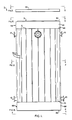
- the shipping cask 1 illustrated therein comprises an elongated generally cylindrical inner vessel 3 which has a metallic, heat-conductive wall 4, preferably formed of low alloy steel, and has a plurality of heat-conductive mutually parallel and uniformly spaced and radially oriented longitudinal ribs 5 joined, preferably welded, to its outer surface.
- a layer of neutron-absorbing cement 7 is applied to and over the outer surface of the vessel 3 between the uniformly spaced ribs 5.
- the layer 7 is formed from a cement having a high percentage content of atomic hydrogen.
- the exterior of the cask 1 is formed by a plurality of plate-like circumferential fins 9, each of which is joined, preferably welded, along its longitudinal edges to outer edge portions of two mutually adjacent ones of the ribs 5 so as to form a secure and watertight joint between the fin and the ribs 5 associated therewith.
- each of the fins 9 is an elongate, rectangular plate of carbon steel approximately 6.5 mm thick.
- the fins 9 advantageously perform three functions. First, they provide an effective means for dissipating heat conducted to them through the ribs 5.
- these fins 9 provide a strong mechanical barrier which retains, supports and protects the layer 7 of neutron-absorbing cement from fracture, even in the event of an accident.
- these fins 9 provide a waterproof barrier preventing the layer of cement from absorbing dissolved radionucleides when the cask is lowered into a spent fuel pool. In the preferred mode of fabricating the cask 1, the fins 9 are first welded into position on the ribs 5 and the neutron-absorbing cement 7 is then poured into the spaces between the vessel 3 and the fins 9.
- Such mode of manufacturing has the advantage of providing a "leak-test" for the welds formed between the fins 9 and the ribs 5, in that any leaking of water and cement occurring on the outer surface of the cask 1 after the neutron-absorbing cement 7 has been poured will serve as an indication telling the manufacturer that the cement needs to be removed in the affected areas, and the affected joints between fins 9 and ribs 5 need to be rewelded to make them watertight.
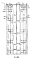
- the cask 1 further includes a basket assembly 11 which is freely insertable into and withdrawable from the inner vessel 3.
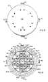
- the basket assembly 11 is formed from two sets of parallel plates 14a-14h and 16a-16h.
- the plates 14a-14h and 16a-16h of the two sets are provided with slots 15 and 17, respectively, which interfit, as seen best from Figure 9C, to form an egg-crate like structure defining square cells 18a-18x.
- the plates 14a-h and 16a-h are formed from a solid sheet of stainless steel approximately 1 cm thick.
- each set of parallel plates 14a-14h or 16a-16h includes a central pair of closely spaced plates 14d, 14e or 16d, 16e, respectively, which due to their central location within the basket assembly 11 lend extra strength to the latter as a whole.
- These central pairs of plates terminate in plate-pair ends 20a, 20b, 21a, 21b, respectively, which provide four uniformly spaced contact surfaces between the periphery of the basket assembly 11 and the inner surface of the vessel 3.
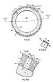
- the basket assembly 11 is circumscribed by a plurality of angular formers 22.1a-22.5a, 22.1b-22.5b, 22.1c-22.5c and 22.1d-22.5d, each of which is formed from three strut plates 24a, 24b, and 24c arranged in tandem and welded, along their edges, to corners defined by plate overhangs 26a, 26b, 26c and 26d.
- each of the strut plates 24 is formed from stainless steel plate material approximately 1 cm thick. Such material is advantageously weld-compatible with the stainless steel plates 14a-14h and 16a-16h used to form the basket assembly 11.
- the angular formers 22.1a-22.5d are spaced apart, preferably uniformly, along the longitudinal axis of the basket assembly 11.
- the total area of the angular formers 22.1a-22.5d relative to the total exterior area of the basket assembly 11 preferably is only about 20 percent.
- the use of such angular formers 22.1a-22.5d in the basket assembly 11 is advantageous in two major respects.
- the multiple, shallow corners which the formers provide over the respective plate overhangs 26a, 26b, 26c and 26d offer four broad areas of contact between the outer surface of the basket assembly 11 and the inner surface of the vessel 3.
- the generally cylindrical inner vessel 3 of the cask 1 has an open top end 28 and a closed bottom end 29 and, at its top end 28, has an inner annular shoulder 32 and an outer annular shoulder 34 each with uniformly spaced bolt holes 33 or 35, respectively, therein.
- the general purpose of these annular shoulders 32, 34 is to support a double-lid closure assembly (not shown), e.g., of the type described in EP-A-0312870.
- the vessel 3 has disposed on its inner surface 36 at least one basket retaining means or assembly 38 (Figs. 6 and 7).
- the basket retaining assembly 38 is formed from a pair of stainless steel dowels 42, 43 measuring preferably about 2.5 cm in diameter.
- the ribs 5 on the outer surface of the vessel 3 which preferably are made of carbon steel have their inner edges 47 joined to the low-alloy steel walls 4 of the vessel 3 by means of fillet welds 48 formed on both sides of each rib 5.
- These fillet welds 48 not only provide a strong mechanical joint between the vessel wall 4 and the ribs 5 but also form highly heat-conductive bridges or paths between the vessel wall 4 and the ribs 5 which will facilitate the conduction of heat from the inner surface 36 of the vessel 3 to its outer surface 45.
- the high-hydrogen content cement 7 applied to the outer surface 45 of the vessel 3 between the ribs 5 provides, due to its high hydrogen content, a high neutron capture cross-section which renders the layers 7 particularly effective as a neutron-radiation absorbing medium.
- This is highly advantageous since the low-alloy steel of the wall 4 of the vessel 3 shields effectively against gamma radiation but not so effectively against neutron radiation.
- the peripheral fins 9 are joined to the outer edges 51 of the respective ribs 5 also by means of fillet welds 53 which are applied to the edges 52a, 52b of the fins 9 and preferably are continuous for the full length of the edges 52a, 52b.
- the peripheral fins 9 and the manner in which they are attached to the outer edges 51 of the ribs 5 offer four distinct advantages.
- the fins 9 may advantageously be used as molds for applying the cementitious material 7 upon the outside surface 45 of the vessel 3.
- the fins 9, having a thickness in the order of about 6.5 mm form a strong mechanical barrier covering the relatively brittle layer of cement 7, thereby protecting it from fracturing or shattering in the event of mechanical shock applied to the exterior of cask 1.
- the fins 9 form a watertight barrier over the layer of cement 7 which renders the cask 1 immersible in a spent-fuel pool without any danger of dissolved radio-nucleides soaking into the porous and water-permeable cement 7. Finally, the peripheral fins 9 provide excellent heat dissipation in a structure which is considerably less fragile than one formed by radially oriented heat dissipating fins alone.
- the exterior surfaces of the fins 9 preferably are covered with a coating 54 rendering the fins 9 corrosion-resistant and sealing the micropores normally existing in the surface of carbon steel, thereby preventing radioactive dust or dissolved radionucleides from lodging in surface pores of the fins 9.
- the coating 54 consists of a base layer 55 of a zinc-containing primer, an intermediate layer 56 of an epoxy polyamide, and top layer 56 of polyester polyurethane.
- the primer is Carbo Zinc -8 manufactured by the Carboline Company located in St. Louis, Missouri
- the top and intermediate layers 56 and 57 are a Series 66 High-Build Epoxoline and a Series 70 and 71 Endura-Shield, both manufactured by Tnemec Company, Inc., located in St. Louis, Missouri.
- the cask 1 includes also a lid assembly 58 comprising a lid 59 with stud-and-nut assemblies 60 (Fig. 5) for fastening it to the vessel 3 at the open end 28 thereof, and an upper ring 62 (Fig. 3) which extends around an upper end portion of the cask 1 and has its lower edge 64 welded (not shown) to the upper edges of the fins 9 so as to create a strong mechanical and watertight joint therebetween.
- the outer edge of the lid 59 abuts the upper edge 63 of the ring 62 when the lid is secured in place upon the cask.
- the cask 1 also includes a floor assembly 65 comprising a disk 66, a spoke assembly 67 provided over the ground-engaging surface of the disk 66 to help in evening out the load applied by the cask 1 upon the disk 66 when standing upright on the ground, and a lower ring 68 which is similar to the upper ring 62 but circumscribes the cask 1 at the very bottom thereof.
- the ring 68 has its bottom edge 69 welded all around to the peripheral edge of the bottom disk 66 so as to form a strong, watertight connection therebetween, and has its upper edge welded to the lower edges of the fins 9 so as to form a strong mechanical and watertight joint therebetween.
- each of the cells 18a-18x of the basket assembly 11 has disposed therein a container 74 for spent fuel rods.
- each of the containers 74 has a lead-in flange 75 disposed thereabout at the upper end thereof in order to facilitate the insertion of fuel rods therein, and has each of its four walls lined on its outer surface, as indicated in Fig. 9D, with a sheet 76a-76d of Boral ® or some other material having a high neutron capture cross-section.
- each of the cells 18a-18x has disposed therein corner brackets 78a-78d for securing the container 74 therein in place.
- the containers 74 are made of anti-corrosive stainless-steel sheet material.
Applications Claiming Priority (2)
| Application Number | Priority Date | Filing Date | Title |
|---|---|---|---|
| US19820888A | 1988-05-24 | 1988-05-24 | |
| US198208 | 1988-05-24 |
Publications (2)
| Publication Number | Publication Date |
|---|---|
| EP0343410A2 true EP0343410A2 (fr) | 1989-11-29 |
| EP0343410A3 EP0343410A3 (fr) | 1990-05-16 |
Family
ID=22732438
Family Applications (1)
| Application Number | Title | Priority Date | Filing Date |
|---|---|---|---|
| EP89108147A Withdrawn EP0343410A3 (fr) | 1988-05-24 | 1989-05-05 | Château de transport pour combustible nucléaire |
Country Status (3)
| Country | Link |
|---|---|
| EP (1) | EP0343410A3 (fr) |
| JP (1) | JPH0672947B2 (fr) |
| KR (1) | KR890017718A (fr) |
Cited By (5)
| Publication number | Priority date | Publication date | Assignee | Title |
|---|---|---|---|---|
| WO1991017547A1 (fr) * | 1990-05-09 | 1991-11-14 | Abb Atom Ab | Conteneur de stockage d'elements combustibles nucleaires epuises |
| US5567952A (en) * | 1994-02-01 | 1996-10-22 | Transnucleaire | Fixing means for the base of a radioactive material transport and/or storage container |
| WO1997026659A1 (fr) * | 1996-01-18 | 1997-07-24 | British Nuclear Fuels Plc | Enveloppe scellee pour assemblages combustibles de reacteur a eau bouillante |
| WO1997029489A1 (fr) * | 1996-02-06 | 1997-08-14 | British Nuclear Fuels Plc | Conteneur etanche pour assemblages combustibles de reacteurs a eau pressurisee |
| EP1235231A1 (fr) * | 2001-02-26 | 2002-08-28 | Mitsubishi Heavy Industries, Ltd. | Conteneur de stockage pour assemblages de combustible nucléaire |
Families Citing this family (4)
| Publication number | Priority date | Publication date | Assignee | Title |
|---|---|---|---|---|
| JPH0766075B2 (ja) * | 1991-07-01 | 1995-07-19 | 日立造船株式会社 | 放射性物体収納容器 |
| JP3416657B2 (ja) | 2001-01-25 | 2003-06-16 | 三菱重工業株式会社 | キャスクおよびキャスクの製造方法 |
| WO2002025670A1 (fr) * | 2000-09-20 | 2002-03-28 | Hitachi, Ltd. | Réservoir servant à transporter du combustible nucléaire |
| WO2004017331A1 (fr) * | 2002-07-23 | 2004-02-26 | Mitsubishi Heavy Industries, Ltd. | Chateau de transport et son procede de production |
Citations (5)
| Publication number | Priority date | Publication date | Assignee | Title |
|---|---|---|---|---|
| FR2471029A1 (fr) * | 1979-11-17 | 1981-06-12 | Transnuklear Gmbh | Vase blinde avec blindage anti-neutrons pour le transport et/ou le stockage de matieres radioactives |
| DE3247085A1 (de) * | 1981-12-22 | 1983-07-28 | Deutsche Gesellschaft für Wiederaufarbeitung von Kernbrennstoffen mbH, 3000 Hannover | Behaelter fuer die langzeitlagerung von abgebrannten kernreaktorbrennelementen |
| EP0087350A1 (fr) * | 1982-02-12 | 1983-08-31 | Framatome | Dispositif de protection neutronique pour produit radio-actif |
| EP0175140A1 (fr) * | 1984-09-04 | 1986-03-26 | Westinghouse Electric Corporation | Récipient pour le stockage de combustible nucléaire épuisé combiné avec un panier continu |
| EP0186487A1 (fr) * | 1984-12-24 | 1986-07-02 | Westinghouse Electric Corporation | Récipient pour le stockage de combustible épuisé comportant un panier à grilles |
-
1989
- 1989-05-05 EP EP89108147A patent/EP0343410A3/fr not_active Withdrawn
- 1989-05-24 KR KR1019890006969A patent/KR890017718A/ko not_active Application Discontinuation
- 1989-05-24 JP JP1131239A patent/JPH0672947B2/ja not_active Expired - Fee Related
Patent Citations (5)
| Publication number | Priority date | Publication date | Assignee | Title |
|---|---|---|---|---|
| FR2471029A1 (fr) * | 1979-11-17 | 1981-06-12 | Transnuklear Gmbh | Vase blinde avec blindage anti-neutrons pour le transport et/ou le stockage de matieres radioactives |
| DE3247085A1 (de) * | 1981-12-22 | 1983-07-28 | Deutsche Gesellschaft für Wiederaufarbeitung von Kernbrennstoffen mbH, 3000 Hannover | Behaelter fuer die langzeitlagerung von abgebrannten kernreaktorbrennelementen |
| EP0087350A1 (fr) * | 1982-02-12 | 1983-08-31 | Framatome | Dispositif de protection neutronique pour produit radio-actif |
| EP0175140A1 (fr) * | 1984-09-04 | 1986-03-26 | Westinghouse Electric Corporation | Récipient pour le stockage de combustible nucléaire épuisé combiné avec un panier continu |
| EP0186487A1 (fr) * | 1984-12-24 | 1986-07-02 | Westinghouse Electric Corporation | Récipient pour le stockage de combustible épuisé comportant un panier à grilles |
Cited By (6)
| Publication number | Priority date | Publication date | Assignee | Title |
|---|---|---|---|---|
| WO1991017547A1 (fr) * | 1990-05-09 | 1991-11-14 | Abb Atom Ab | Conteneur de stockage d'elements combustibles nucleaires epuises |
| US5567952A (en) * | 1994-02-01 | 1996-10-22 | Transnucleaire | Fixing means for the base of a radioactive material transport and/or storage container |
| WO1997026659A1 (fr) * | 1996-01-18 | 1997-07-24 | British Nuclear Fuels Plc | Enveloppe scellee pour assemblages combustibles de reacteur a eau bouillante |
| WO1997029489A1 (fr) * | 1996-02-06 | 1997-08-14 | British Nuclear Fuels Plc | Conteneur etanche pour assemblages combustibles de reacteurs a eau pressurisee |
| EP1235231A1 (fr) * | 2001-02-26 | 2002-08-28 | Mitsubishi Heavy Industries, Ltd. | Conteneur de stockage pour assemblages de combustible nucléaire |
| US6898258B2 (en) | 2001-02-26 | 2005-05-24 | Mitsubishi Heavy Industries, Ltd. | Cask |
Also Published As
| Publication number | Publication date |
|---|---|
| KR890017718A (ko) | 1989-12-18 |
| JPH0224599A (ja) | 1990-01-26 |
| JPH0672947B2 (ja) | 1994-09-14 |
| EP0343410A3 (fr) | 1990-05-16 |
Similar Documents
| Publication | Publication Date | Title |
|---|---|---|
| US4997618A (en) | Fuel rod shipping cask having peripheral fins | |
| US5063299A (en) | Low cost, minimum weight fuel assembly storage cask and method of construction thereof | |
| US4896046A (en) | Fuel rod shipping cask having peripheral fins | |
| US5651038A (en) | Sealed basket for pressurized water reactor fuel assemblies | |
| EP0673541B1 (fr) | Conteneur pour le transport et le stockage d'elements du combustible nucleaire | |
| US4800283A (en) | Shock-absorbing and heat conductive basket for use in a fuel rod transportation cask | |
| KR102094251B1 (ko) | 사용후 핵연료의 저장 및 운송을 위한 시스템 | |
| US4666659A (en) | Shipping and storage container for spent nuclear fuel | |
| US4972087A (en) | Shipping container for low level radioactive or toxic materials | |
| US20060056569A1 (en) | System and method for packaging a nuclear reactor pressure vessel head | |
| EP4018462B1 (fr) | Enceinte blindée contre les rayonnements pour château de combustible nucléaire usé | |
| US11676736B2 (en) | Ventilated metal storage overpack (VMSO) | |
| US5848111A (en) | Spent nuclear fuel container | |
| EP0343410A2 (fr) | Château de transport pour combustible nucléaire | |
| US5894134A (en) | Shipping container for radioactive material | |
| US5612543A (en) | Sealed basket for boiling water reactor fuel assemblies | |
| KR20190117759A (ko) | 사용후핵연료의 저장 및 운반용 컨테이너 | |
| US6784444B2 (en) | Containment and transportation of decommissioned nuclear reactor pressure vessels | |
| RU2459295C1 (ru) | Транспортный упаковочный комплект для отработавших тепловыделяющих сборок ядерных реакторов | |
| JP5808303B2 (ja) | 放射性物質輸送貯蔵容器 | |
| RU2463677C1 (ru) | Транспортный упаковочный комплект для отработавших тепловыделяющих сборок ядерных реакторов | |
| JP2692215B2 (ja) | 使用済燃料用キャスクへの燃料集合体の収納方法 | |
| JP2003270382A (ja) | 放射性物質格納容器および放射性物質の格納方法 | |
| JP4316153B2 (ja) | 使用済燃料保管キャスク | |
| JP2003315488A (ja) | 使用済核燃料収納容器 |
Legal Events
| Date | Code | Title | Description |
|---|---|---|---|
| PUAI | Public reference made under article 153(3) epc to a published international application that has entered the european phase |
Free format text: ORIGINAL CODE: 0009012 |
|
| AK | Designated contracting states |
Kind code of ref document: A2 Designated state(s): BE DE ES FR GB IT SE |
|
| PUAL | Search report despatched |
Free format text: ORIGINAL CODE: 0009013 |
|
| AK | Designated contracting states |
Kind code of ref document: A3 Designated state(s): BE DE ES FR GB IT SE |
|
| 17P | Request for examination filed |
Effective date: 19901113 |
|
| 17Q | First examination report despatched |
Effective date: 19930510 |
|
| STAA | Information on the status of an ep patent application or granted ep patent |
Free format text: STATUS: THE APPLICATION HAS BEEN WITHDRAWN |
|
| 18W | Application withdrawn |
Withdrawal date: 19931023 |