EP0343356B1 - Transformer station or the like with ventilation openings for an air current - Google Patents
Transformer station or the like with ventilation openings for an air current Download PDFInfo
- Publication number
- EP0343356B1 EP0343356B1 EP89106377A EP89106377A EP0343356B1 EP 0343356 B1 EP0343356 B1 EP 0343356B1 EP 89106377 A EP89106377 A EP 89106377A EP 89106377 A EP89106377 A EP 89106377A EP 0343356 B1 EP0343356 B1 EP 0343356B1
- Authority
- EP
- European Patent Office
- Prior art keywords
- hood
- door
- transformer station
- transformer
- switchgear
- Prior art date
- Legal status (The legal status is an assumption and is not a legal conclusion. Google has not performed a legal analysis and makes no representation as to the accuracy of the status listed.)
- Expired - Lifetime
Links
Images


Classifications
-
- H—ELECTRICITY
- H02—GENERATION; CONVERSION OR DISTRIBUTION OF ELECTRIC POWER
- H02B—BOARDS, SUBSTATIONS OR SWITCHING ARRANGEMENTS FOR THE SUPPLY OR DISTRIBUTION OF ELECTRIC POWER
- H02B7/00—Enclosed substations, e.g. compact substations
- H02B7/06—Distribution substations, e.g. for urban network
-
- E—FIXED CONSTRUCTIONS
- E04—BUILDING
- E04H—BUILDINGS OR LIKE STRUCTURES FOR PARTICULAR PURPOSES; SWIMMING OR SPLASH BATHS OR POOLS; MASTS; FENCING; TENTS OR CANOPIES, IN GENERAL
- E04H5/00—Buildings or groups of buildings for industrial or agricultural purposes
- E04H5/02—Buildings or groups of buildings for industrial purposes, e.g. for power-plants or factories
- E04H5/04—Transformer houses; Substations or switchgear houses
Definitions
- the invention relates to a network station made of a concrete body with a ventilation openings for a door in both the upper and lower areas and with at least one voltage switch arranged in the interior of the door, behind which at least one transformer is placed.
- the medium and low-voltage switchgear are arranged in the front room, i.e. near the door, while the transformer is in the rear room of the station building and thus the farthest away from ventilation openings if these are only arranged on the front of the network station.
- DE-B-1 559 144 shows a network station of the type mentioned at the beginning using a transformer station made from two identical concrete channels.
- a cell for the voltage switches and the transformer is delimited by two doors; the air currents are drawn from the ventilation slots in one door through the other door.
- Such air routing is not sensible in monolithic network stations with a single door, which are preferably partially lowered into the ground, which also applies to the document according to DE-U-7 401 064; the medium and low voltage parts are encapsulated there, the transformer is supplied with circulating air through openings opposite.
- the inventor has set himself the goal of improving the guidance of the supply air flow in network stations of the type mentioned at the outset and, above all, of offering good ventilation for partially buried network stations with walls closed on three sides.
- the voltage switch is arranged at a distance from the floor of the network station and opposite it is the door in which the ventilation openings are exclusively arranged, the ventilation routing within the network station being determined by a hood which is located between the one or the lower area of the door arranged ventilation openings and the ventilation openings arranged in the upper area is attached to the door and forms a flow path for the ventilation flow, which is first passed under the voltage switch to the transformer and then past it to the ventilation openings.
- the hood, the ventilation opening (s) spanned and to separate its downward-facing hood opening from the voltage switches by means of guide devices, preferably by means of an intermediate plate.
- the easy-to-use hood directs the supply air flow from the ventilation opening and the switchgear directly to the transformer, from where it can reach the exhaust air opening in the door of the station building - swiping over the cover and along the switchgear.
- the simple solution is particularly suitable for installation in compact stations, but is also suitable for a station whose ventilation openings are only made in the door of the building.
- the hood expediently consists of thin sheet metal and preferably has a bevel all around, which significantly increases the rigidity of the hood.
- a compact station 10 made of a monolithically cast concrete body 12 and attached roof plate 14 is lowered beneath it at a distance h from its base 15 to the surrounding turf base 8.
- doors 20 are inserted into that concrete body 12 above the turf base in such a way that the side walls 16 of the concrete body 12 form pilaster strips 17 of depth e which overlap the doors 20.
- Ventilation openings 22 are arranged in the lower region of the door 20 and ventilation openings 24 are arranged in the upper region thereof. Between these ventilation openings 22 and ventilation openings 24, a hood 30 is articulated on the inside of the door 20 at 26, which is made of sheet metal with a ridge strip 27 and subsequent guide wall 28 and two side walls 29.
- the guide wall 28 which runs obliquely in the installed position according to FIG. 3 can be extended by a vertical base strip 28 m .
- the hood 30 spans the ventilation openings 22 such that the hood opening 31 points downward and its guide wall 28 to switching devices 34.
- the supply air is thus forced to take the path indicated by arrow x under the switching devices 34 standing on supports 36 to a transformer 38 installed in the interior 11 of the compact station 10 on its rear wall 18. This can be supported by an additional horizontal intermediate plate 32, which stretches from the hood 30 to one of the carriers 36. With 33 chamfered edge strips of the hood 30 are designated.
- the drawn pilasters 17 improve the air draft x, y in front of the doors 20 and also prevent undesired access by a saw or the like. Tool to the door hinges arranged on the side walls 16, which are not shown for reasons of clarity.
- the cold supply air cools the transformer 38 and rises up there as heated exhaust air, sweeps over the hood 30 along the switching devices 34 to the ventilation openings 24 and passes through them - according to arrow y - to the outside.
- the hood 30 can, instead of being articulated, also be hung on the inside of the door 20 or screwed to it. But it can also be attached to the carriers 36 of the switching devices 34.
- the shape of the hood 30 is always designed such that the free cross section of the ventilation path corresponds at least to that of the ventilation opening 22 at every point.
- hood 30 If the hood 30 is in the way when accessing the switching devices 34, it can be gripped and easily removed by a handle 40 in the example of FIG. 3, set aside and reattached.
Abstract
Description
Die Erfindung betrifft eine Netzstation aus einem Betonkörper mit einer sowohl im oberen als auch im unteren Bereich Be- und Entlüftungsöffnungen für einen Lüftungsstrom aufweisenden Tür sowie mit zumindest einem in ihrem Innenraum türnah angeordneten Spannungsschalter, hinter dem wenigstens ein Transformator aufgesetzt ist.The invention relates to a network station made of a concrete body with a ventilation openings for a door in both the upper and lower areas and with at least one voltage switch arranged in the interior of the door, behind which at least one transformer is placed.
Bei der Luftführung in Netzstationen ist es wichtig, die kalte Zuluft zuerst zum Transformator zu führen und dann zu den Mittel- und Niederspannungsschaltgeräten, nach denen die Abluft abgeleitet werden soll. Ein Zuluftschacht ist teuer, vergrößert den Grundrißbedarf der Netzstation und bildet eine ständige Gefahr für Wassereintritt in die Netzstation.When routing air in network stations, it is important to first lead the cold supply air to the transformer and then to the medium and low-voltage switchgear, from which the exhaust air is to be discharged. A supply air shaft is expensive, increases the floor plan of the network station and creates a constant risk of water entering the network station.
Bei bedienungsfreundlichen Netzstationen sind die Mittel- und Niederspannungsschaltgeräte im vorderen Raum, also in der Nähe der Tür angeordnet, während der Transformator im hinteren Raum des Stationsgebäudes steht und damit am weitesten entfernt von Belüftungsöffnungen, wenn diese ausschließlich an der Frontseite der Netzstation angeordnet sind.In the case of user-friendly network stations, the medium and low-voltage switchgear are arranged in the front room, i.e. near the door, while the transformer is in the rear room of the station building and thus the farthest away from ventilation openings if these are only arranged on the front of the network station.
Eine Netzstation der eingangs erwähnten Art zeigt DE-B-1 559 144 anhand einer aus zwei formgleichen Betonrinnen gefertigten Transformatorenstation. In diesem Gebilde ist durch zwei Türen eine Zelle für die Spannungsschalter und den Transformator abgegrenzt, die Luftströmungen ziehen von Belüftungsschlitzen der einen Tür durch die andere Tür ab. Eine solche Luftführung ist bei monolythischen Netzstationen mit einer einzigen Tür, welche bevorzugt teilweise in das Erdreich abgesenkt werden, nicht sinnvoll, was auch für die Schrift nach DE-U-7 401 064 zutrifft; dort sind die Mittel- und Niederspannungsteile abgekapselt, der Transformator wird durch gegenüberliegende Öffnungen mit Umluft versorgt.DE-B-1 559 144 shows a network station of the type mentioned at the beginning using a transformer station made from two identical concrete channels. In this structure, a cell for the voltage switches and the transformer is delimited by two doors; the air currents are drawn from the ventilation slots in one door through the other door. Such air routing is not sensible in monolithic network stations with a single door, which are preferably partially lowered into the ground, which also applies to the document according to DE-U-7 401 064; the medium and low voltage parts are encapsulated there, the transformer is supplied with circulating air through openings opposite.
In Kenntnis dieses Standes der Technik hat sich der Erfinder das Ziel gesetzt, bei Netzstationen der eingangs erwähnten Art die Führung des Zuluftstromes zu verbessern und vor allem für teilweise eingegrabene Netzstationen mit dreiseitig geschlossenen Wänden eine gute Durchlüftung anzubieten.Knowing this state of the art, the inventor has set himself the goal of improving the guidance of the supply air flow in network stations of the type mentioned at the outset and, above all, of offering good ventilation for partially buried network stations with walls closed on three sides.
Zur Lösung dieser Aufgabe führt die Lehre nach dem Patentanspruch 1; der Spannungsschalter ist in Abstand zum Boden der Netzstation angeordnet und ihm gegenüber die Tür angebracht, in der die Be- und Entlüftungsöffnungen ausschließlich angeordnet sind, wobei die Lüftungsführung innerhalb der Netzstation von einer Haube bestimmt wird, die zwischen der/den im unteren Bereich der Tür angeordneten Belüftungsöffnungen und den im oberen Bereich angeordneten Entlüftungsöffnungen an der Tür angebracht ist und eine Strömungsbahn für den Lüftungsstrom bildet, der zuerst unter dem Spannungsschalter zum Transformator und dann an ihm vorbei zu den Entlüftungsöffnungen geleitet ist. Dabei hat es sich als günstig erwiesen, die Haube, die Belüftungsöffnung/en überspannen zu lassen und ihre nach unten weisende Haubenöffnung von den Spannungsschaltern durch Leiteinrichtungen zu trennen, bevorzugt durch ein Zwischenblech.To solve this problem, the teaching according to claim 1; the voltage switch is arranged at a distance from the floor of the network station and opposite it is the door in which the ventilation openings are exclusively arranged, the ventilation routing within the network station being determined by a hood which is located between the one or the lower area of the door arranged ventilation openings and the ventilation openings arranged in the upper area is attached to the door and forms a flow path for the ventilation flow, which is first passed under the voltage switch to the transformer and then past it to the ventilation openings. It has proven to be advantageous to have the hood, the ventilation opening (s) spanned and to separate its downward-facing hood opening from the voltage switches by means of guide devices, preferably by means of an intermediate plate.
Weitere vorteilhafte Ausgestaltungen sind den Unteransprüchen zu entnehmen.Further advantageous refinements can be found in the subclaims.
Die leicht einsetzbare Haube leitet den Zuluftstrom von der Belüftungsöffnung und den Schaltgeräten direkt zum Transformator, von wo aus sie -- über der Haube und an den Schaltgeräten entlangstreichen -- zur Abluftöffnung in der Tür des Stationsgebäudes gelangen kann. Die einfache Lösung eignet sich insbesondere zum Einbau in Kompaktstationen, ist aber auch für solch eine Station geeignet, deren Be- und Entlüftungsöffnungen ausschließlich in der Tür des Gebäudes angebracht sind.The easy-to-use hood directs the supply air flow from the ventilation opening and the switchgear directly to the transformer, from where it can reach the exhaust air opening in the door of the station building - swiping over the cover and along the switchgear. The simple solution is particularly suitable for installation in compact stations, but is also suitable for a station whose ventilation openings are only made in the door of the building.
Die Haube besteht zweckmäßigerweise aus dünnem Blech und weist bevorzugt ringsum eine Abkantung auf, welche die Steifigkeit der Haube wesentlich erhöht.The hood expediently consists of thin sheet metal and preferably has a bevel all around, which significantly increases the rigidity of the hood.
Weitere Vorteile, Merkmale und Einzelheiten der Erfindung ergeben sich aus der nachfolgenden Beschreibung bevorzugter Ausführungsbeispiele sowie anhand der Zeichnung; diese zeigt in:
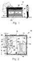
- Fig. 1: die Frontansicht einer Kompaktstation mit einer Haube zur Führung eines Lüftungsstromes;
- Fig. 2: einen Querschnitt durch die Kompaktstation nach Fig. 1 und
- Fig. 3: eine Schrägsicht auf eine andere Ausführung der Haube.
- 1: the front view of a compact station with a hood for guiding a ventilation flow;
- 2: a cross section through the compact station according to FIGS. 1 and
- Fig. 3: an oblique view of another version of the hood.
Eine Kompaktstation 10 aus einem monolithisch gegossenen Betonkörper 12 und aufgesetzter Dachplatte 14 ist mit einem Abstand h ihres Bodens 15 zur umgebenden Rasensohle 8 unter diese abgesenkt. An der in Fig. 1 erkennbaren Frontseite der Kompaktstation 10 sind in jenen Betonkörper 12 oberhalb der Rasensohle 8 Türen 20 so eingesetzt, daß die Seitenwände 16 des Betonkörpers 12 die Türen 20 übergreifende Lisenen 17 der Tiefe e bilden.A
Im unteren Bereich der Tür 20 sind Belüftungsöffnungen 22 und in deren oberen Bereich Entlüftungsöffnungen 24 angeordnet. Zwischen diesen Belüftungsöffnungen 22 und Entlüftungsöffnungen 24 ist an der Innenseite der Tür 20 bei 26 eine Haube 30 angelenkt, die mit einem Firststreifen 27 und anschließender Leitwand 28 sowie zwei Seitenwänden 29 aus Blech hergestellt ist. Die in Einbaulage nach Fig. 3 schräg verlaufende Leitwand 28 kann durch einen vertikalen Sockelstreifen 28m verlängert sein.
Die Haube 30 überspannt die Belüftungsöffnungen 22 so, daß die Haubenöffnung 31 abwärts und ihre Leitwand 28 zu Schaltgeräten 34 weist. Somit ist die Zuluft gezwungen, den mit Pfeil x angedeuteten Weg unter den auf Trägern 36 stehenden Schaltgeräten 34 zu einem im Innenraum 11 der Kompaktstation 10 an deren Rückwand 18 aufgestellten Transformator 38 zu nehmen. Dies kann durch ein zusätzliches horizontales Zwischenblech 32 unterstützt werden, welches sich von der Haube 30 zu einem der Träger 36 spannt. Mit 33 sind abgekantete Randstreifen der Haube 30 bezeichnet.The
Die vorgezogenen Lisenen 17 verbessern den Luftzug x,y vor den Türen 20 und verhindern zudem einen unerwünschten Zugriff einer Säge od. dgl. Werkzeug zu den an den Seitenwänden 16 angeordneten -- aus Gründen der Übersicht nicht dargestellten -- Türscharnieren.The drawn
Die kalte Zuluft kühlt den Transformator 38 und steigt an ihm als erwärmte Abluft nach oben, streicht über der Haube 30 an den Schaltgeräten 34 entlang zu den Entlüftungsöffnungen 24 und gelangt durch diese -- entsprechend Pfeil y -- nach außen.The cold supply air cools the
Die Haube 30 kann bei einem anderen Ausführungsbeispiel -- statt angelenkt -- an der Innenseite der Tür 20 auch in diese eingehängt oder mit ihr verschraubt werden. Sie kann aber auch an den Trägern 36 der Schaltgeräte 34 befestigt werden.In another exemplary embodiment, the
Die Form der Haube 30 ist aber stets so gestaltet, daß der freie Querschnitt des Lüftungsweges an jeder Stelle mindestens demjenigen der Belüftungsöffnung 22 entspricht.However, the shape of the
Ist die Haube 30 beim Zutritt zu den Schaltgeräten 34 im Wege, so läßt sie sich beim Beispiel der Fig. 3 an einem Griff 40 fassen und leicht entfernen, zur Seite legen und wieder einrastend anbringen.If the
Claims (9)
characterised in that
the switchgear (34) is mounted at a distance (h) from the base (15) of the transformer station (10) and the door (20) in which the ventilation openings (22, 24) are exclusively arranged is arranged opposite said switchgear, that the air is guided within the transformer station (10) by means of a hood (30), which is mounted on the door (20) between the ventilation opening(s) (22) arranged in the lower region of the door (20) and the ventilation opening(s) (24) arranged in the upper region and forms a flow path for the air current (x, y), which is guided first below the switchgear (34) to the transformer (38) and then via the switchgear (34) to the ventilation opening(s) (24).
Priority Applications (1)
| Application Number | Priority Date | Filing Date | Title |
|---|---|---|---|
| AT89106377T ATE74175T1 (en) | 1988-04-13 | 1989-04-11 | POWER STATION OR SIMILAR WITH VENTILATION AND VENTILATION OPENINGS FOR A VENTILATION FLOW. |
Applications Claiming Priority (2)
| Application Number | Priority Date | Filing Date | Title |
|---|---|---|---|
| DE8804820U | 1988-04-13 | ||
| DE8804820U DE8804820U1 (en) | 1988-04-13 | 1988-04-13 |
Publications (2)
| Publication Number | Publication Date |
|---|---|
| EP0343356A1 EP0343356A1 (en) | 1989-11-29 |
| EP0343356B1 true EP0343356B1 (en) | 1992-03-25 |
Family
ID=6822850
Family Applications (1)
| Application Number | Title | Priority Date | Filing Date |
|---|---|---|---|
| EP89106377A Expired - Lifetime EP0343356B1 (en) | 1988-04-13 | 1989-04-11 | Transformer station or the like with ventilation openings for an air current |
Country Status (3)
| Country | Link |
|---|---|
| EP (1) | EP0343356B1 (en) |
| AT (1) | ATE74175T1 (en) |
| DE (2) | DE8804820U1 (en) |
Families Citing this family (7)
| Publication number | Priority date | Publication date | Assignee | Title |
|---|---|---|---|---|
| DE9206780U1 (en) * | 1992-03-31 | 1992-08-06 | Betonbau Gmbh, 6833 Waghaeusel, De | |
| FR2717321B1 (en) * | 1994-03-08 | 1996-04-26 | Merlin Gerin | Electrical transformer station. |
| FR2776431B1 (en) * | 1998-03-19 | 2000-05-12 | Schneider Electric Ind Sa | ELECTRICAL STATION COMPRISING A VENTILATION DEVICE |
| DE10008727B4 (en) * | 1999-02-25 | 2005-12-29 | Betonbau Gmbh | substation |
| GB2556604B (en) | 2015-09-11 | 2022-04-27 | Aggreko Llc | Modular energy storage system |
| CN105490196A (en) * | 2016-02-03 | 2016-04-13 | 天津合纵电力设备有限公司 | Compact box type substation |
| CN111852100A (en) * | 2020-07-22 | 2020-10-30 | 国网安徽省电力有限公司经济技术研究院 | Safety protection device for transformer substation |
Family Cites Families (5)
| Publication number | Priority date | Publication date | Assignee | Title |
|---|---|---|---|---|
| DE1559144C3 (en) * | 1965-07-08 | 1974-06-06 | Fritz Driescher Spezialfabrik Fuer Elektrizitaetswerksbedarf, 4070 Rheydt | Transformer station |
| DE7401064U (en) * | 1974-01-14 | 1980-01-24 | Koerber, Rudolf, Dipl.-Ing., 4000 Duesseldorf | Low-rise, medium-voltage network station made of precast concrete parts that can be lowered into the ground |
| DE7607474U1 (en) * | 1976-03-11 | 1976-07-29 | Fritz Driescher Spezialfabrik Fuer Elektrizitaetswerksbedarf, 5144 Wegberg | PREFABRICATED TRANSFORMER STATION |
| DE2706958A1 (en) * | 1977-02-18 | 1978-08-31 | Gervin Josef Mueller | EXPLOSION HAZARD BUILDING WITH AT LEAST ONE VENT |
| FR2515717B1 (en) * | 1981-11-04 | 1985-09-13 | Cattin Jean | TRANSFORMER-TYPE CIVIL ENGINEERING BUILDING |
-
1988
- 1988-04-13 DE DE8804820U patent/DE8804820U1/de not_active Expired
-
1989
- 1989-04-11 EP EP89106377A patent/EP0343356B1/en not_active Expired - Lifetime
- 1989-04-11 AT AT89106377T patent/ATE74175T1/en active
- 1989-04-11 DE DE8989106377T patent/DE58901015D1/en not_active Expired - Lifetime
Also Published As
| Publication number | Publication date |
|---|---|
| ATE74175T1 (en) | 1992-04-15 |
| DE58901015D1 (en) | 1992-04-30 |
| DE8804820U1 (en) | 1988-09-01 |
| EP0343356A1 (en) | 1989-11-29 |
Similar Documents
| Publication | Publication Date | Title |
|---|---|---|
| DE3822600A1 (en) | PET DOOR | |
| EP0775459B1 (en) | Show case for displaying goods | |
| EP0343356B1 (en) | Transformer station or the like with ventilation openings for an air current | |
| EP0768741B1 (en) | Transportable container for transformer station | |
| CH681403A5 (en) | ||
| WO1996024236A1 (en) | Switch cabinet with rack and mounting plate | |
| DE60029751T2 (en) | Door arrangement and method for covering the edge of a door opening | |
| DE2110089A1 (en) | Explosive, essentially single-cell building | |
| DE1640734C3 (en) | Flush-mounted distributor with fully insulated equipment compartment and sheet steel frame | |
| DE3025441C2 (en) | External wall box for the combustion air and exhaust gas duct of a device that works with a burner system | |
| EP0465934B1 (en) | Building module | |
| DE2528300C3 (en) | Control cabinet with tightly closing door | |
| DE3406628C2 (en) | ||
| EP0011336A1 (en) | Sealing for a door without a sill and with a revolving wing | |
| DE19631232C2 (en) | Shower cubicle with shower plateau | |
| DE19614593A1 (en) | Transportable room cell as a substation | |
| EP0062937A1 (en) | Electrical switchgear cabinet | |
| DE2401532A1 (en) | Pedestrian-bearing sunken prefabricated MV substation - with box-shaped concrete base and hooded roof with folding detachable elements | |
| DE10009013A1 (en) | Transportable room cell for use as transformer station | |
| DE3637063A1 (en) | Covering for discharge channels | |
| DE3110304A1 (en) | Unitised unit, in particular substation which is at the risk of explosion | |
| EP0609727A1 (en) | Fan casing for the arrangement in a passage opening | |
| EP1194360B1 (en) | Panel construction for an elevator shaft door | |
| DE19710593A1 (en) | Transportable cell, especially as enclosure for transformer | |
| EP1036535A2 (en) | Shower partition |
Legal Events
| Date | Code | Title | Description |
|---|---|---|---|
| PUAI | Public reference made under article 153(3) epc to a published international application that has entered the european phase |
Free format text: ORIGINAL CODE: 0009012 |
|
| AK | Designated contracting states |
Kind code of ref document: A1 Designated state(s): AT BE CH DE ES FR GB GR IT LI LU NL SE |
|
| RBV | Designated contracting states (corrected) |
Designated state(s): AT BE CH DE FR IT LI NL |
|
| 17P | Request for examination filed |
Effective date: 19900126 |
|
| ITCL | It: translation for ep claims filed |
Representative=s name: STUDIO BIANCHETTI |
|
| EL | Fr: translation of claims filed | ||
| 17Q | First examination report despatched |
Effective date: 19901210 |
|
| GRAA | (expected) grant |
Free format text: ORIGINAL CODE: 0009210 |
|
| AK | Designated contracting states |
Kind code of ref document: B1 Designated state(s): AT BE CH DE FR IT LI NL |
|
| REF | Corresponds to: |
Ref document number: 74175 Country of ref document: AT Date of ref document: 19920415 Kind code of ref document: T |
|
| ITF | It: translation for a ep patent filed |
Owner name: DE DOMINICIS & MAYER S.R.L. |
|
| REF | Corresponds to: |
Ref document number: 58901015 Country of ref document: DE Date of ref document: 19920430 |
|
| ET | Fr: translation filed | ||
| PLBE | No opposition filed within time limit |
Free format text: ORIGINAL CODE: 0009261 |
|
| STAA | Information on the status of an ep patent application or granted ep patent |
Free format text: STATUS: NO OPPOSITION FILED WITHIN TIME LIMIT |
|
| 26N | No opposition filed | ||
| PGFP | Annual fee paid to national office [announced via postgrant information from national office to epo] |
Ref country code: NL Payment date: 19950430 Year of fee payment: 7 |
|
| PGFP | Annual fee paid to national office [announced via postgrant information from national office to epo] |
Ref country code: BE Payment date: 19950508 Year of fee payment: 7 |
|
| PG25 | Lapsed in a contracting state [announced via postgrant information from national office to epo] |
Ref country code: BE Effective date: 19960430 |
|
| BERE | Be: lapsed |
Owner name: BETONBAU G.M.B.H. Effective date: 19960430 |
|
| PG25 | Lapsed in a contracting state [announced via postgrant information from national office to epo] |
Ref country code: NL Effective date: 19961101 |
|
| NLV4 | Nl: lapsed or anulled due to non-payment of the annual fee |
Effective date: 19961101 |
|
| PGFP | Annual fee paid to national office [announced via postgrant information from national office to epo] |
Ref country code: CH Payment date: 19971020 Year of fee payment: 9 |
|
| PG25 | Lapsed in a contracting state [announced via postgrant information from national office to epo] |
Ref country code: LI Free format text: LAPSE BECAUSE OF NON-PAYMENT OF DUE FEES Effective date: 19980430 Ref country code: CH Free format text: LAPSE BECAUSE OF NON-PAYMENT OF DUE FEES Effective date: 19980430 |
|
| REG | Reference to a national code |
Ref country code: CH Ref legal event code: PL |
|
| PGFP | Annual fee paid to national office [announced via postgrant information from national office to epo] |
Ref country code: FR Payment date: 19990415 Year of fee payment: 11 |
|
| PGFP | Annual fee paid to national office [announced via postgrant information from national office to epo] |
Ref country code: AT Payment date: 19990421 Year of fee payment: 11 |
|
| PGFP | Annual fee paid to national office [announced via postgrant information from national office to epo] |
Ref country code: DE Payment date: 19990617 Year of fee payment: 11 |
|
| PG25 | Lapsed in a contracting state [announced via postgrant information from national office to epo] |
Ref country code: AT Free format text: LAPSE BECAUSE OF NON-PAYMENT OF DUE FEES Effective date: 20000411 |
|
| PG25 | Lapsed in a contracting state [announced via postgrant information from national office to epo] |
Ref country code: FR Free format text: LAPSE BECAUSE OF NON-PAYMENT OF DUE FEES Effective date: 20001229 |
|
| PG25 | Lapsed in a contracting state [announced via postgrant information from national office to epo] |
Ref country code: DE Free format text: LAPSE BECAUSE OF NON-PAYMENT OF DUE FEES Effective date: 20010201 |
|
| REG | Reference to a national code |
Ref country code: FR Ref legal event code: ST |
|
| PG25 | Lapsed in a contracting state [announced via postgrant information from national office to epo] |
Ref country code: IT Free format text: LAPSE BECAUSE OF NON-PAYMENT OF DUE FEES;WARNING: LAPSES OF ITALIAN PATENTS WITH EFFECTIVE DATE BEFORE 2007 MAY HAVE OCCURRED AT ANY TIME BEFORE 2007. THE CORRECT EFFECTIVE DATE MAY BE DIFFERENT FROM THE ONE RECORDED. Effective date: 20050411 |