EP0343314A2 - Verfahren zur Herstellung einer Riemenscheibe - Google Patents
Verfahren zur Herstellung einer Riemenscheibe Download PDFInfo
- Publication number
- EP0343314A2 EP0343314A2 EP89100057A EP89100057A EP0343314A2 EP 0343314 A2 EP0343314 A2 EP 0343314A2 EP 89100057 A EP89100057 A EP 89100057A EP 89100057 A EP89100057 A EP 89100057A EP 0343314 A2 EP0343314 A2 EP 0343314A2
- Authority
- EP
- European Patent Office
- Prior art keywords
- pulley
- hub
- metal blank
- making
- wall thickness
- Prior art date
- Legal status (The legal status is an assumption and is not a legal conclusion. Google has not performed a legal analysis and makes no representation as to the accuracy of the status listed.)
- Granted
Links
Images
Classifications
-
- B—PERFORMING OPERATIONS; TRANSPORTING
- B21—MECHANICAL METAL-WORKING WITHOUT ESSENTIALLY REMOVING MATERIAL; PUNCHING METAL
- B21D—WORKING OR PROCESSING OF SHEET METAL OR METAL TUBES, RODS OR PROFILES WITHOUT ESSENTIALLY REMOVING MATERIAL; PUNCHING METAL
- B21D53/00—Making other particular articles
- B21D53/26—Making other particular articles wheels or the like
- B21D53/261—Making other particular articles wheels or the like pulleys
Definitions
- the invention relates to a method according to the preamble of the main claim.
- a generic method is described for example in US-PS 42 73 547.
- the procedure is such that a metal blank is deep-pressed in a first process step, so that a pot-like pressed part is obtained.
- This pot-like pressed part obtained in a first method step has in the area of the hub surface and in the area of the coaxial, i.e. the cylindrical wall extending substantially perpendicular to the hub surface has the same wall thickness.
- This first process step is shown in FIGS. 1 and 2 of US Pat. No. 4,273,547.
- This known method therefore essentially requires five successive, absolutely essential, essential processing steps, the forces to be used for the "collapse" being considerable, so that large mechanical expenditure is required to absorb these high pressures.
- the invention has for its object to simplify the generic method in such a way that, despite less mechanical effort, the cylindrical peripheral surface formed, which is also referred to as the contact surface, has a greater wall thickness than the actual hub surface.
- This object on which the invention is based is achieved in that the metal blank is flanged in a first process step in a departure from the previous method of operation and then the flanging is flattened to form the contact surface.
- This mode of operation eliminates the processing of the formed that was previously required in the prior art Edge avoided and instead of the deep-drawing press producing a pot-like body, a simple border roller is used.
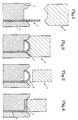
- a metal blank 1 is shown, which is clamped between two chuck jaws 4 and 5 according to FIG. 1.
- a squeeze roller 7 is shown and when the squeeze roller 7 is fed onto the border 2, the end product shown in FIG. 4 is reached, namely a support surface 3 which has a greater thickness than the hub surface 8 of the metal blank 1.
- Grooves running in the circumferential direction can be incorporated into the bearing surface thus formed, so that, for example, a poly-V pulley is formed or it is also possible to apply transverse toothings so that a cross-toothed pulley can be created.
- the round blank can have a thickness of 1.6 mm, it being possible to bring the contact surface 3 to a thickness of 3.2 mm by using the new method. It is known that a wall thickness increase of about 20 can be achieved even when boarding.
Landscapes
- Engineering & Computer Science (AREA)
- Mechanical Engineering (AREA)
- Pulleys (AREA)
Abstract
Description
- Die Erfindung bezieht sich auf ein Verfahren gemäß dem Oberbegriff des Hauptanspruches.
- Ein gattungsbildendes Verfahren ist beispielsweise in der US-PS 42 73 547 beschrieben. Bei diesem bekannten Verfahren zur Herstellung von Riemenscheiben oder Poly-V-Scheiben wird so vorgegangen, daß eine Metallronde in einem ersten Verfahrensschritt tiefgepreßt wird, so daß ein topfartiges Preßteil erzielt wird. Dieses in einem ersten Verfahrensschritt erzielte topfartige Preßteil weist im Bereich der Nabenfläche und im Bereich der sich koaxial, d.h. im wesentlichen senkrecht zur Nabenfläche erstreckenden zylindrischen Fläche die gleiche Wandstärke auf. Dieser erste Verfahrensschritt ist in den Fig. 1 und 2 der US-PS 42 73 547 dargestellt.
- Anschließend ist es - was in der US-PS 42 73 547 nicht dargestellt ist - erforderlich, den Randbereich der gebildeten zylindrischen Fläche fein zu bearbeiten.
- Als nächster Verfahrensschritt schließt sich ein sogenanntes "Kollapsen" der zylindrischen Randfläche an, das in den Fig. 6a und 6b der US-PS 42 73 547 dargestellt ist. Durch dieses "Kollapsen" wird die zylindrische Randfläche durch Verformung in ihrer Höhe reduziert, wobei gleichzeitig der Randbereich zwischen der Nabenfläche und der zylindrischen Fläche eingefaltet wird.
- Der so gekollapste Randbereich wird dann über eine Zudrückrolle umgeformt und zusammengedrückt, wie dies in den Fig. 8b und 9 der US-PS 42 73 547 dargestellt ist.
- Dieses bekannte Verfahren benötigt also im wesentlichen fünf aufeinanderfolgende, unbedingt erforderliche wesentliche Bearbeitungsschritte, wobei die für das "Kollapsen" aufzuwendenden Kräfte erheblich sind, so daß, um diese hohen Drücke aufzunehmen, große maschinelle Aufwendungen erforderlich sind.
- Der Erfindung liegt die Aufgabe zugrunde, das gattungsbildende Verfahren so zu vereinfachen, daß trotz geringerem maschinellem Aufwand erreicht wird, daß die gebildete zylindrische Umfangsfläche, die auch als Auflagefläche bezeichnet wird, eine größere Wandstärke als die eigentliche Nabenfläche aufweist.
- Diese der Erfindung zugrundeliegende Aufgabe wird dadurch gelöst, daß die Metallronde in Abkehr von der bisherigen Arbeitsweise in einem ersten Verfahrensschritt bordiert wird und dann die Bordierung zur Bildung der Auflagefläche flachgedrückt wird. Durch diese Arbeitsweise wird das bisher im Stand der Technik erforderliche Bearbeiten des gebildeten Randes vermieden und anstelle der einen topfartigen Körper erzeugenden Tiefziehpresse wird eine einfache Bordierrolle eingesetzt.
- Anstelle des "Kollapsens" im Stand der Technik wird nunmehr ein einfaches Zudrücken der Bordierung erforderlich und mit diesen drei einfachen Verfahrensschritten wird eine Riemenscheibe geschaffen, die der Anforderung entspricht, daß die eigentliche Nabenfläche dünner als die eigentliche Auflagefläche ausgebildet ist, wobei gleichzeitig die Durchführung dieses Verfahrens kostengünstig realisiert werden kann.
- Ein Ausführungsbeispiel der Erfindung wird nachfolgend anhand der Zeichnung erläutert. Die Zeichnung zeigt dabei in
- Fig. 1 die in ein Futter eingespannte Ronde mit noch nicht tätiggewordener Bordierrolle, in
- Fig. 2 die Bordierrolle einschließlich der erzielten Bordierung, in
- Fig. 3 die erzielte Bordierung bei noch nicht tätiggewordener Zudrückrolle und in
- Fig. 4 das erzielte Produkt, das als Endprodukt oder als Zwischenprodukt geeignet ist.
- In der Zeichnung ist eine Metallronde 1 gezeigt, die gemäß Fig. 1 zwischen zwei Futterbacken 4 und 5 eingespannt ist. Eine Bordierrolle 6, die bei ihrer Zuführung auf die Futterbacken 4 und 5, wie dies in Fig. 2 dargestellt ist, schafft eine Bordierung 2.
- In den Fig. 3 und 4 ist eine Zudrückrolle 7 gezeigt und bei Zuführen der Zudrückrolle 7 auf die Bordierung 2 wird das in Fig. 4 dargestellte Endprodukt erreicht, nämlich eine Auflagefläche 3, die eine größere Stärke als die Nabenfläche 8 der Metallronde 1 aufweist.
- In die so gebildete Auflagefläche können in Umfangsrichtung verlaufende Nuten eingearbeitet werden, so daß beispielsweise eine Poly-V-Scheibe gebildet wird oder es ist auch möglich, Querverzahnungen aufzubringen, so daß eine querverzahnte Riemenscheibe erstellt werden kann.
- Als Ausführungsbeispiel sei darauf hingewiesen, daß beispielsweise die Ronde eine Stärke von 1,6 mm aufweisen kann, wobei durch die Anwendung des neuen Verfahrens dann die Auflagefläche 3 auf eine Stärke von 3,2 mm gebracht werden kann. Hierbei ist es bekannt, daß bereits beim Bordieren eine Wandstärkenvergrößerung um etwa 20 erreichbar ist.
Claims (1)
- Verfahren zur Herstellung einer Riemenscheibe aus einer Metallronde mit einer Nabe und einer sich koaxial, d.h. im wesentlichen senkrecht zur Nabenfläche erstreckenden zylindrischen Auflagefläche, die eine größere Wandstärke als die Nabe aufweist und mit in Umfangsrichtung verlaufenden Nuten ausgerüstet oder querverzahnt ausgebildet werden kann, dadurch gekennzeichnet, daß die Metallronde (1) in ihrem Umfangsbereich bordiert und anschließend die Bordierung (2) zur Bildung der Auflagefläche (3) flachgedrückt wird.
Applications Claiming Priority (4)
| Application Number | Priority Date | Filing Date | Title |
|---|---|---|---|
| DE3818041 | 1988-05-27 | ||
| DE3818041 | 1988-05-27 | ||
| DE3819957A DE3819957C2 (de) | 1988-05-27 | 1988-06-11 | Verfahren zur Herstellung einer Riemenscheibe |
| DE3819957 | 1988-06-11 |
Publications (3)
| Publication Number | Publication Date |
|---|---|
| EP0343314A2 true EP0343314A2 (de) | 1989-11-29 |
| EP0343314A3 EP0343314A3 (de) | 1991-01-23 |
| EP0343314B1 EP0343314B1 (de) | 1993-03-17 |
Family
ID=25868515
Family Applications (1)
| Application Number | Title | Priority Date | Filing Date |
|---|---|---|---|
| EP19890100057 Expired - Lifetime EP0343314B1 (de) | 1988-05-27 | 1989-01-04 | Verfahren zur Herstellung einer Riemenscheibe |
Country Status (2)
| Country | Link |
|---|---|
| EP (1) | EP0343314B1 (de) |
| ES (1) | ES2038792T3 (de) |
Cited By (7)
| Publication number | Priority date | Publication date | Assignee | Title |
|---|---|---|---|---|
| EP0493333A1 (de) * | 1990-12-12 | 1992-07-01 | FATA EUROPEAN GROUP S.r.l. | Spaltwerkzeug für Metallronden |
| DE19620178A1 (de) * | 1996-05-20 | 1996-10-17 | Leifeld Gmbh & Co | Verfahren zum Herstellen einer Poly-V-Scheibe |
| WO1998006521A1 (de) * | 1996-08-14 | 1998-02-19 | Wf-Maschinenbau Und Blechformtechnik Gmbh & Co. Kommanditgesellschaft | Verfahren und vorrichtung zur herstellung eines aussen verzahnten getriebeteiles |
| KR100291682B1 (ko) * | 1992-02-19 | 2001-06-01 | 제이. 브라이언 콜번 | 강판제 치차의 냉간성형방법 및 강판제 냉간성형치차 |
| DE102012100985A1 (de) | 2012-02-07 | 2013-08-08 | WF Maschinenbau und Blechformtechnik GmbH & Co. KG | Verfahren zur Herstellung von Getriebeteilen, insbesondere Riemenscheiben, Dämpferscheiben oder Dämpfergehäusen |
| CN113770222A (zh) * | 2021-09-25 | 2021-12-10 | 潍坊斐越工贸有限公司 | 一种热旋压支重轮成型方法 |
| DE102010010269C5 (de) | 2010-03-05 | 2023-11-16 | Mercedes-Benz Group AG | Verfahren zum Herstellen eines Statorträgers |
Families Citing this family (2)
| Publication number | Priority date | Publication date | Assignee | Title |
|---|---|---|---|---|
| DE19524089C1 (de) * | 1995-07-01 | 1996-09-05 | Wf Maschinenbau Blechformtech | Verfahren und Vorrichtung zur Herstellung eines Getriebeteiles aus einer Metallronde |
| DE10156086B4 (de) * | 2001-11-16 | 2006-09-14 | Winkelmann Powertrain Components Gmbh & Co. Kg | Verfahren zur Herstellung eines rotationssymmetrischen Bauteils |
Family Cites Families (5)
| Publication number | Priority date | Publication date | Assignee | Title |
|---|---|---|---|---|
| US1943224A (en) * | 1932-07-18 | 1934-01-09 | Kelsey Hayes Wheel Corp | Method of forming brake drums |
| US4273547A (en) * | 1975-11-04 | 1981-06-16 | Drive Manufacturing Inc. | Method of pulley manufacture and product |
| US4631946A (en) * | 1984-03-02 | 1986-12-30 | Kabushiki Kaisha Kanemitsu | Method of manufacturing sheet metal made poly-V pulleys |
| DE3445942A1 (de) * | 1984-12-17 | 1986-07-10 | KLIFA - Fahrzeugteile GmbH & Co, 6800 Mannheim | Verfahren und vorrichtung zum herstellen einer mehrrilligen antriebsscheibe aus blech |
| DE3736096C1 (en) * | 1987-10-24 | 1988-09-15 | Wf Maschinenbau Blechformtech | Apparatus for the production of multi-groove V-belt pulleys |
-
1989
- 1989-01-04 EP EP19890100057 patent/EP0343314B1/de not_active Expired - Lifetime
- 1989-01-04 ES ES89100057T patent/ES2038792T3/es not_active Expired - Lifetime
Cited By (10)
| Publication number | Priority date | Publication date | Assignee | Title |
|---|---|---|---|---|
| EP0493333A1 (de) * | 1990-12-12 | 1992-07-01 | FATA EUROPEAN GROUP S.r.l. | Spaltwerkzeug für Metallronden |
| KR100291682B1 (ko) * | 1992-02-19 | 2001-06-01 | 제이. 브라이언 콜번 | 강판제 치차의 냉간성형방법 및 강판제 냉간성형치차 |
| DE19620178A1 (de) * | 1996-05-20 | 1996-10-17 | Leifeld Gmbh & Co | Verfahren zum Herstellen einer Poly-V-Scheibe |
| DE19620178C2 (de) * | 1996-05-20 | 1999-03-25 | Leifeld Gmbh & Co | Verfahren zum Herstellen einer Poly-V-Scheibe |
| WO1998006521A1 (de) * | 1996-08-14 | 1998-02-19 | Wf-Maschinenbau Und Blechformtechnik Gmbh & Co. Kommanditgesellschaft | Verfahren und vorrichtung zur herstellung eines aussen verzahnten getriebeteiles |
| US6161409A (en) * | 1996-08-14 | 2000-12-19 | Wf-Maschinebau Und Blechformtechnik Gmbh & Co. Kommanditgessellschaft | Process and device for manufacturing a gear part with outer teeth |
| DE102010010269C5 (de) | 2010-03-05 | 2023-11-16 | Mercedes-Benz Group AG | Verfahren zum Herstellen eines Statorträgers |
| DE102012100985A1 (de) | 2012-02-07 | 2013-08-08 | WF Maschinenbau und Blechformtechnik GmbH & Co. KG | Verfahren zur Herstellung von Getriebeteilen, insbesondere Riemenscheiben, Dämpferscheiben oder Dämpfergehäusen |
| CN113770222A (zh) * | 2021-09-25 | 2021-12-10 | 潍坊斐越工贸有限公司 | 一种热旋压支重轮成型方法 |
| CN113770222B (zh) * | 2021-09-25 | 2024-03-08 | 潍坊斐越工贸有限公司 | 一种热旋压支重轮成型方法 |
Also Published As
| Publication number | Publication date |
|---|---|
| EP0343314A3 (de) | 1991-01-23 |
| EP0343314B1 (de) | 1993-03-17 |
| ES2038792T3 (es) | 1993-08-01 |
Similar Documents
| Publication | Publication Date | Title |
|---|---|---|
| EP0725693B1 (de) | Verfahren zur spanlosen herstellung einer nabe eines die nabe aufweisenden getriebeteiles | |
| DE3336581C2 (de) | Mehrfach-Keilriemenscheibe und Verfahren zu ihrer Herstellung | |
| DE69901616T2 (de) | Verfahren und vorrichtung zur herstellung eines dosendeckels mit einer verstärkungswulst | |
| DE2633039C3 (de) | Aus einem becherförmigen Blechteil geformte Keilriemenscheibe und Verfahren zu deren Herstellung | |
| DE3042312A1 (de) | Riemenscheibe und verfahren zu ihrer herstellung | |
| DE19581564B3 (de) | Verfahren zum Herstellen einer Mehrfach-Keilriemenscheibe aus Blech | |
| DE69400378T2 (de) | Klemmring und Verfahren zur Herstellung | |
| EP0397901B1 (de) | Verfahren zur Herstellung einer Riemenscheibe | |
| EP0343314B1 (de) | Verfahren zur Herstellung einer Riemenscheibe | |
| WO1998006521A1 (de) | Verfahren und vorrichtung zur herstellung eines aussen verzahnten getriebeteiles | |
| DE3883325T2 (de) | Lammellierter Körper von Metallblechen. | |
| DE2406361A1 (de) | Ungeteiltes gleitlager bzw. gehaeusebuchse mit stossfuge und mit formgeschlossenem bund sowie verfahren und vorrichtung zu deren herstellung | |
| DE3819957C1 (de) | ||
| DE19708027A1 (de) | Verfahren zum Herstellen einer metallischen Zahnradscheibe | |
| DE2624872C3 (de) | Verfahren zum Herstellen von ungeteilten Felgen | |
| DE2911542C2 (de) | Verfahren zur Herstellung von zylindrischen Metallkörpern hoher Präzision | |
| EP0808678B1 (de) | Verfahren und Vorrichtung zum Herstellen einer Poly-V-Scheibe | |
| DE69304432T2 (de) | Verfahren zum Formen eines ringförmigen Elementes | |
| DE19860045A1 (de) | Verfahren zum Herstellen eines ringförmigen Blechteils mit einer Umfangswand | |
| DE3422040A1 (de) | Stuelp-umformverfahren zur herstellung von doppelwandigen zylindrischen werkstuecken sowie umformwerkzeug hierfuer | |
| DE19913091A1 (de) | Mehrstufige Riemenscheibe sowie Verfahren zu ihrer Herstellung | |
| DE19860732A1 (de) | Verfahren zur Herstellung einer Luftreifenfelge | |
| DE4013238C2 (de) | Vorrichtung zur Herstellung von Werkstücken, wie Poly-V-Scheiben, Felgen o. dgl. | |
| DE3445942A1 (de) | Verfahren und vorrichtung zum herstellen einer mehrrilligen antriebsscheibe aus blech | |
| DE19913090A1 (de) | Verfahren zur Herstellung einer mehrstufigen Riemenscheibe |
Legal Events
| Date | Code | Title | Description |
|---|---|---|---|
| PUAI | Public reference made under article 153(3) epc to a published international application that has entered the european phase |
Free format text: ORIGINAL CODE: 0009012 |
|
| AK | Designated contracting states |
Kind code of ref document: A2 Designated state(s): DE ES FR GB IT NL SE |
|
| PUAL | Search report despatched |
Free format text: ORIGINAL CODE: 0009013 |
|
| AK | Designated contracting states |
Kind code of ref document: A3 Designated state(s): DE ES FR GB IT NL SE |
|
| 17P | Request for examination filed |
Effective date: 19910430 |
|
| RAP1 | Party data changed (applicant data changed or rights of an application transferred) |
Owner name: WINKELMANN & PANNHOFF GMBH |
|
| 17Q | First examination report despatched |
Effective date: 19920224 |
|
| GRAA | (expected) grant |
Free format text: ORIGINAL CODE: 0009210 |
|
| AK | Designated contracting states |
Kind code of ref document: B1 Designated state(s): DE ES FR GB IT NL SE |
|
| REF | Corresponds to: |
Ref document number: 58903776 Country of ref document: DE Date of ref document: 19930422 |
|
| GBT | Gb: translation of ep patent filed (gb section 77(6)(a)/1977) |
Effective date: 19930504 |
|
| ET | Fr: translation filed | ||
| ITF | It: translation for a ep patent filed | ||
| REG | Reference to a national code |
Ref country code: ES Ref legal event code: FG2A Ref document number: 2038792 Country of ref document: ES Kind code of ref document: T3 |
|
| PLBI | Opposition filed |
Free format text: ORIGINAL CODE: 0009260 |
|
| 26 | Opposition filed |
Opponent name: KIEKERT & NIELAND PRESS- UND STANZWERK GMBH 6 CO. Effective date: 19930820 |
|
| PLBI | Opposition filed |
Free format text: ORIGINAL CODE: 0009260 |
|
| NLR1 | Nl: opposition has been filed with the epo |
Opponent name: KIEKERT & NIELAND PRESS- UND STANZWERK GMBH & CO. |
|
| PLBI | Opposition filed |
Free format text: ORIGINAL CODE: 0009260 |
|
| 26 | Opposition filed |
Opponent name: HOHE KG Effective date: 19931210 Opponent name: KIEKERT & NIELAND PRESS- UND STANZWERK GMBH 6 CO. Effective date: 19930820 |
|
| 26 | Opposition filed |
Opponent name: ZERRATH ULRICH Effective date: 19931217 Opponent name: HOHE KG Effective date: 19931210 Opponent name: KIEKERT & NIELAND PRESS- UND STANZWERK GMBH 6 CO. Effective date: 19930820 |
|
| NLR1 | Nl: opposition has been filed with the epo |
Opponent name: ZERRATH ULRICH Opponent name: HOHE KG |
|
| EAL | Se: european patent in force in sweden |
Ref document number: 89100057.2 |
|
| APAC | Appeal dossier modified |
Free format text: ORIGINAL CODE: EPIDOS NOAPO |
|
| PLBN | Opposition rejected |
Free format text: ORIGINAL CODE: 0009273 |
|
| STAA | Information on the status of an ep patent application or granted ep patent |
Free format text: STATUS: OPPOSITION REJECTED |
|
| 27O | Opposition rejected |
Effective date: 19960123 |
|
| NLR2 | Nl: decision of opposition | ||
| PGFP | Annual fee paid to national office [announced via postgrant information from national office to epo] |
Ref country code: GB Payment date: 20001222 Year of fee payment: 13 |
|
| PGFP | Annual fee paid to national office [announced via postgrant information from national office to epo] |
Ref country code: SE Payment date: 20010116 Year of fee payment: 13 |
|
| PGFP | Annual fee paid to national office [announced via postgrant information from national office to epo] |
Ref country code: NL Payment date: 20010131 Year of fee payment: 13 |
|
| REG | Reference to a national code |
Ref country code: GB Ref legal event code: IF02 |
|
| PG25 | Lapsed in a contracting state [announced via postgrant information from national office to epo] |
Ref country code: GB Free format text: LAPSE BECAUSE OF NON-PAYMENT OF DUE FEES Effective date: 20020104 |
|
| PG25 | Lapsed in a contracting state [announced via postgrant information from national office to epo] |
Ref country code: SE Free format text: LAPSE BECAUSE OF NON-PAYMENT OF DUE FEES Effective date: 20020105 |
|
| PG25 | Lapsed in a contracting state [announced via postgrant information from national office to epo] |
Ref country code: NL Free format text: LAPSE BECAUSE OF NON-PAYMENT OF DUE FEES Effective date: 20020801 |
|
| GBPC | Gb: european patent ceased through non-payment of renewal fee |
Effective date: 20020104 |
|
| EUG | Se: european patent has lapsed |
Ref document number: 89100057.2 |
|
| NLV4 | Nl: lapsed or anulled due to non-payment of the annual fee |
Effective date: 20020801 |
|
| PGFP | Annual fee paid to national office [announced via postgrant information from national office to epo] |
Ref country code: DE Payment date: 20021218 Year of fee payment: 15 |
|
| PGFP | Annual fee paid to national office [announced via postgrant information from national office to epo] |
Ref country code: FR Payment date: 20030120 Year of fee payment: 15 |
|
| PGFP | Annual fee paid to national office [announced via postgrant information from national office to epo] |
Ref country code: ES Payment date: 20030130 Year of fee payment: 15 |
|
| PG25 | Lapsed in a contracting state [announced via postgrant information from national office to epo] |
Ref country code: ES Free format text: LAPSE BECAUSE OF NON-PAYMENT OF DUE FEES Effective date: 20040105 |
|
| PG25 | Lapsed in a contracting state [announced via postgrant information from national office to epo] |
Ref country code: DE Free format text: LAPSE BECAUSE OF NON-PAYMENT OF DUE FEES Effective date: 20040803 |
|
| PG25 | Lapsed in a contracting state [announced via postgrant information from national office to epo] |
Ref country code: FR Free format text: LAPSE BECAUSE OF NON-PAYMENT OF DUE FEES Effective date: 20040930 |
|
| REG | Reference to a national code |
Ref country code: FR Ref legal event code: ST |
|
| PG25 | Lapsed in a contracting state [announced via postgrant information from national office to epo] |
Ref country code: IT Free format text: LAPSE BECAUSE OF NON-PAYMENT OF DUE FEES;WARNING: LAPSES OF ITALIAN PATENTS WITH EFFECTIVE DATE BEFORE 2007 MAY HAVE OCCURRED AT ANY TIME BEFORE 2007. THE CORRECT EFFECTIVE DATE MAY BE DIFFERENT FROM THE ONE RECORDED. Effective date: 20050104 |
|
| REG | Reference to a national code |
Ref country code: ES Ref legal event code: FD2A Effective date: 20040105 |
|
| APAH | Appeal reference modified |
Free format text: ORIGINAL CODE: EPIDOSCREFNO |