EP0343311B1 - Klingenabnahme- und/oder -befestigungsmechanismus sowie diesen Mechanismus enthaltende Spender- und Extraktions-/Wegwerfvorrichtung - Google Patents
Klingenabnahme- und/oder -befestigungsmechanismus sowie diesen Mechanismus enthaltende Spender- und Extraktions-/Wegwerfvorrichtung Download PDFInfo
- Publication number
- EP0343311B1 EP0343311B1 EP19880830235 EP88830235A EP0343311B1 EP 0343311 B1 EP0343311 B1 EP 0343311B1 EP 19880830235 EP19880830235 EP 19880830235 EP 88830235 A EP88830235 A EP 88830235A EP 0343311 B1 EP0343311 B1 EP 0343311B1
- Authority
- EP
- European Patent Office
- Prior art keywords
- blade
- handle
- passageway
- extracting means
- handle guide
- Prior art date
- Legal status (The legal status is an assumption and is not a legal conclusion. Google has not performed a legal analysis and makes no representation as to the accuracy of the status listed.)
- Expired - Lifetime
Links
- 238000003780 insertion Methods 0.000 claims description 13
- 230000037431 insertion Effects 0.000 claims description 13
- 230000013011 mating Effects 0.000 claims description 11
- 230000000994 depressogenic effect Effects 0.000 description 6
- 230000002093 peripheral effect Effects 0.000 description 6
- 238000000034 method Methods 0.000 description 4
- 239000000853 adhesive Substances 0.000 description 3
- 230000001070 adhesive effect Effects 0.000 description 3
- 238000001356 surgical procedure Methods 0.000 description 3
- 238000004806 packaging method and process Methods 0.000 description 2
- IAYPIBMASNFSPL-UHFFFAOYSA-N Ethylene oxide Chemical compound C1CO1 IAYPIBMASNFSPL-UHFFFAOYSA-N 0.000 description 1
- 208000027418 Wounds and injury Diseases 0.000 description 1
- 210000001015 abdomen Anatomy 0.000 description 1
- 230000003213 activating effect Effects 0.000 description 1
- 230000001427 coherent effect Effects 0.000 description 1
- 239000002131 composite material Substances 0.000 description 1
- 238000010276 construction Methods 0.000 description 1
- 230000006378 damage Effects 0.000 description 1
- 210000005069 ears Anatomy 0.000 description 1
- 208000014674 injury Diseases 0.000 description 1
- 239000000463 material Substances 0.000 description 1
- 239000002184 metal Substances 0.000 description 1
- 238000012986 modification Methods 0.000 description 1
- 230000004048 modification Effects 0.000 description 1
- 230000007170 pathology Effects 0.000 description 1
- 230000005855 radiation Effects 0.000 description 1
- 230000000284 resting effect Effects 0.000 description 1
- 230000000717 retained effect Effects 0.000 description 1
- 238000012414 sterilization procedure Methods 0.000 description 1
- 239000012780 transparent material Substances 0.000 description 1
Images


Classifications
-
- A—HUMAN NECESSITIES
- A61—MEDICAL OR VETERINARY SCIENCE; HYGIENE
- A61B—DIAGNOSIS; SURGERY; IDENTIFICATION
- A61B17/00—Surgical instruments, devices or methods
- A61B17/32—Surgical cutting instruments
- A61B17/3209—Incision instruments
- A61B17/3211—Surgical scalpels, knives; Accessories therefor
- A61B17/3215—Packages or dispensers for scalpel blades
Definitions
- the present invention relates to the art of cutting blade dispensing and disposal, and, in particular, to a mechanism for blade removal and/or mounting used to provide convenient storage, dispensing, and disposal apparatus for cutting blades which can be mounted on blade handles by means of a mating elongated slot and boss.
- the rear edge of the blade In order to remove a blade of this nature from a scalpel handle, the rear edge of the blade must be separated from the handle to disengage the rear end of the blade aperture from the rear end of the boss so that the blade can then be pushed forward until the undercut boss clears the narrowed forward portion of the blade aperture permitting the blade to be cleared of the handle.
- a sharp edge is essential in conducting a surgical operation.
- blades tend to lose their edge very quickly in such procedures so it is common to use several blades during a single surgical procedure.
- removal of a used blade from the handle and replacement of the blade with a new sterile blade is a frequent occurrence in the course of a surgical procedure.
- U.S. Patent No 3,172,316 to Grieshaber shows a blade removing tool formed from tubing and having an elongated handle.
- One end is flattened somewhat so as to provide flat opposed surfaces in which are formed opposed channel-like grooves which function as guide tracks for the boss portion of the scalpel when the tool and the scalpel boss portion are assembled.
- Extending longitudinally from one flat surface of the flattened end portion of the handle are two spaced-apart prongs which are inclined upwardly a slight amount. The space between the prongs is such as to permit the slender boss portion of the scalpel handle to pass therebetween, the free end of each prong being offset upwardly.
- the blade end of the scalpel handle can be initially inserted longitudinally through the open flat end of the tube between the channel-like grooves.
- the offset ends of the tool prong slidably engaging the under surface of the blade until they engage behind the innermost edge of the blade adjacent the scalpel handle.
- the inclination of the prongs causes the innermost edge portion of the accommodated blade to be flexed upwardly so that each edge portion thereof will clear the slender boss portion of the scalpel when the scalpel is withdrawn longitudinally from the flattened end of the tool.
- the blade of the scalpel is held in place by the offset ends of the prongs during withdrawal of the scalpel handle.
- U.S. Patent No. 4,180,162 to Magney shows a combination dispenser-disposal cartridge for a surgical blade which includes an elongated open-top box with means for receiving and positioning the blade in a curved position to accept the mating boss of a scalpel handle.
- the box also includes means for stripping a used blade from the scalpel handle and retaining it within the box for disposal.
- the blade is packed in the box so that it curvingly extends from the forward tip towards the shank tip to facilitate insertion of a boss of a scalpel handle into the elongated slot, which is then moved forward and withdrawn with the blade mounted on the handle.
- Other devices include the scalpel blade remover shown in U.S. Patent No. 4,378,624 to Klingerberg which includes a fixed block in combination with a second movable block having a slot between such blocks and a tab provided on the movable block to engage an end of the blade and move it relative to the body of the blade to disengage it from the handle.
- the blocks are mounted on a supporting surface beneath which a sterile disposal box may be disposed.
- U.S. Patent No. 4,318,473 to Sandel shows a surgical blade removal and disposal device which operates by inserting a handle with a blade mounted thereon through a guide means so that the rear of the blade is disposed over spaced apart shoulders after which the handle is urged downward tending to bow the blade, thus disengaging the rear of the inserted portion from the rear edge of the blade slot to allow the handle to slide relative to the blade.
- the blade tends to move with the handle as a result of friction between the blade and the handle unit until it encounters the front wall of a stop which prevents further movement of the blade rearwardly.
- One of the problems encountered with the Sandel blade removal device is the severe bend imposed on the blade when it is fit over the spaced-apart shoulders to guide the blade to the rear stop. This causes a high degree of friction between the blade slot and the handle boss making removal of the blade very difficult.
- U.S. Patent No. 4,344,532 to Eldridge, Jr., et al. discloses a surgical blade remover having a wedge shaped support member which tapers from its front side to its back side.
- the support has one or more mutually parallel latitudinal slots open at one end and along their length extending from the front side of the support to its interior.
- the slots are sized to receive the tang of the blade holder while preventing the blade itself from passing therethrough and the surface of each of the support members bordering the slot is covered with an adhesive which holds the blade in place while the handle is pivoted downward in the slot away from the blade.
- the slots are shown to have modifications contoured to compliment the shape of the blade and/or to provide a notch to receive a portion of the hilt of the blade in order to assist in blade removal.
- U.S. Patent No. 4,120,397 to Neumann shows a unit for accommodating disposable blade-like articles in which the underside of a blade such as a scalpel blade, slidably engages a resilient tongue-like element which is deflected upwardly.
- the tongue-like element has mounted thereon cam means having surfaces which can be pushed against the blade to unseat the rear of the blade away from a boss on the blade handle.
- U.S. Patent No. 4,106,620 to Brimmer, et al shows a surgical blade dispenser and disposal assembly which includes blades individually positioned and supported within the box between a slot in a forward wall and a slot in a rearward wall which holds the blades in such a fashion as to slightly deform them in a lateral curve for receipt of a boss of a surgical blade holder in the elongated slot formed in the body of the blade.
- the blades can be removed by insertion of the blade bearing handle through the aperture and wedged rearwardly against projecting ears. The handle is then moved laterally to separate the rear of the blade from the boss and remove the handle completely off the blade.
- This device has proved to be cumbersome and the removal apparatus does not provide for efficient removal of the blades.
- Another object of the invention is to provide a scalpel blade dispenser holder which gives quick and easy access to a variety of scalpel blades.
- a further object of the present invention is to provide for safe storage of scalpel blades during the course of surgical operations.
- Another object of the invention is to facilitate the safe disposal of used and contaminated scalpel blades.
- Another object of the invention is to permit the quick and accurate inventory of scalpel blades usually conducted at the conclusion of surgical operations.
- the present invention includes a mechanism which can be used for both mounting and removing a blade having an elongated slot mounting means from a blade handle which has a mounting boss for insertion into the elongated slot.
- the mechanism includes a handle guide which forms one side of a passageway for insertion of the blade handle, the handle guide having a flexible body portion which is sufficiently flexible to allow deflection of the handle for withdrawal of the boss out of mating relationship with the elongated slot of the blade.
- Another element of the mechanism is a blade extracting means fixed opposite the handle guide which forms a second side of the passageway, the extracting means having a blade retaining projection arranged adjacent the passageway which can be actuated to prevent withdrawal of a blade from the passageway.
- the mechanism further includes a actuation means fixed for actuation of the blade extracting means upon deflection of the handle sufficiently to disengage the boss out of a mating relationship with the elongated slot.
- a device of the present invention can also include a well for holding a blade in a position for mounting on a handle as well as for receiving a blade once used.
- the well can be used as a disposal receptacle when the mechanism is used merely as a blade disarmer.
- the well can also include a blade support which holds a blade in a mounting position while preserving the blade's cutting edge.
- the blade extracting means includes a flexible arm extending from a point at one end of the passageway and extends along the passageway to an operative end, the blade retaining projection being fixed at the operative end so that it is positioned out of the passageway in the unactuated condition and so that it can be drawn over the passageway when actuated.
- the actuation means includes a latch means secured to, for example, the handle guide, the latch means including a yoke extending around the passageway and a yoke tab extending around the blade removal hook arm whereby the tab is drawn into actuating contact with the arm when the handle guide is deflected away from the blade extracting means.
- the latch means can be secured to the blade removal arm while the yoke extends around the passageway and the yoke tab extends around the handle guide.
- the yoke tab can extend around either the arm or the handle guide a distance sufficient to permit insertion of the handle through the passageway without actuating the actuating arm.
- the device can preferably be from about 5cm (2") to about 7cm (2 3/4") high, from about 7.5cm (3") to about 10cm (4") long, and from about 4.5cm (1 3/4") to about 7cm (2 3/4") wide at the base, and can be provided with an adhesive on the bottom surface for securing the device in place during use.
- a medical operating team can be provided with quick and easy access to a variety of scalpel blades in the device which permit the safe handling of the blades by mechanically mounting and dismounting as required.
- the blades can be identified as new or used and the device permits a blade count at the conclusion of the operation to be performed more quickly and accurately while allowing for the safe storage and disposal of the used scalpel blades.
- the invention can be used to provide a blade disposal container which contains the mechanism described above for disarming a blade from a handle.
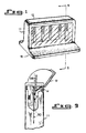
- FIG. 1 there can be seen a device constructed in accordance with the present invention for packaging a series of blades, such as scalpel blades, for mounting on a scalpel blade handle, and for dismounting the blade from the handle and disposal after use.
- the device is shown with five blades which can be packaged, sterilized, and delivered to the operating environment for selection and use by the operating team.
- the dispenser can have a transparent housing 11 whereby the different size and type of blades can be conveniently viewed by the surgeon or assistant.
- Figure 2 and 3 show the relationship of the scalpel blade to the scalpel blade handle in a fully assembled position in Figure 2, and in a disassembled configuration in Figure 3.
- a blade 50 having an elongated aperture 51 with a reduced sized section 53 and an enlarged section 52. It is also known that the elongated aperture can have three variations in aperture size rather than merely two as shown in Figure 3.
- a blade handle 55 is shown with an elongated forward portion 57 provided with a peripheral mounting slot 59.
- the peripheral slot 59 can be formed by provision of a raised boss 56 having the undercut peripheral slot 59.
- the boss 56 extends outwardly from the forward end portion 57.
- Figure 3 there is shown a partial cutaway of the boss 56 to show the peripheral mounting slot 59 formed as an undercut of the boss 56.
- the raised boss portion 56 In order to mount the blade 50 onto the handle 55, the raised boss portion 56 must be directed into the enlarged portion 52 of the elongated aperture 51 and thrust forward so that the entire body of raised boss 56 is inserted into the elongated aperture 51.
- the narrowed portion 53 of the elongated aperture is frictionally engaged by the peripheral slot 59 to secure the blade 50 on the handle 55. It is noted that the blade is secured on the handle when the rear portion 52 of aperture 51 drops over the rear portion of the raised boss 56 and snaps into mating relationship therewith.
- the operative mechanism of the present invention is show with a blade 50 shown in phantom therein.
- the operative mechanism includes a handle guide assembly 20 having a lower frame 21, which can be part of a molded base portion, and an upper handle guide 22 having a guiding surface 26.
- the handle guide assembly is fixed within housing 11 opposite a blade hook assembly 30 to form one side of a passageway for the blade and blade handle.
- the blade hook assembly 30 in turn, includes a housing support part 31, as well as a leg portion 32 which extends upwardly to a blade removal hook 37 having a blade removal surface 34.
- a third portion of the operative mechanism of the present invention is a latch hook assembly 40 which is rigidly fixed to the handle guide 22 by means of a latch bar 41 and continues perimetrically around the blade passage by means of a latch extension 42.
- a latch hook 43 At the end of the latch extension 42 is a latch hook 43, which extends around the leg 32 a distance "f" from the leg 32 to permit deflection of the handle guide assembly 20 a distance sufficient to permit insertion of a handle tip in the passageway for mounting a blade thereon.
- FIG 8 an alternative embodiment of the present invention is shown with the latch hook assembly rigidly affixed to the blade removal hook rather than the handle guide assembly.
- These parts of the configuration shown in Figure 8 which have been rearranged are designated with primed numbers to indicate that they parts with similar function, but with a different configuration.
- a lid 12 preferably, having a living hinge 13, which can be raised rearwardly (see Figure 9) to expose a blade use indicator tab 14 located immediately above the packaged blade.
- the blade indicator tab 14 is depressed downwardly to be captured between converging shoulders 15 provided in the housing, so that once depressed, use of the blade is memoralized by the downwardly-retained tab.
- FIGs 10 The operation by which a blade is mounted on the handle is shown in Figures 10 add 11.
- the front portion 57 of a blade handle 55 is thrust downwardly to depress the blade indicator tab 14 and to gain access into the passageway between the handle guide assembly 20 and the hook removal assembly 30.
- the handle can be seen as it has been engaged with the elongated aperture 51 of the blade 50
- the tab 14 which has been depressed is retained in the depressed condition by frictional fit between converging shoulders 15. Since there is a distance "f" between the leg 32 and the latch hook 43, the handle guide can be deflected to a certain extent without activating the blade removal assembly 30.
- the entire assembly can be vertically removed from the mechanism.
- the removal of a blade from a handle is explained with reference to Figure 12.
- the blade and handle assembly can be inserted once again through the opening provided by the permanently depressed tab 14 and into the passageway between the handle guide assembly 20 and the blade hook assembly 30.
- the handle 55 can be deflected toward the handle guide assembly 20 and away from the blade removal assembly 30, i.e., to the right as shown in Figure 12.
- the handle 55 strikes against the upper handle guide 22 thereby urging the handle guide assembly with the latch hook assembly 40 rigidly fixed thereto away from the passageway.
- the latch hook 43 thereby traverses through the distance "f” and strikes the rear of leg 32 of blade removal hook assembly 30 thereby urging it over the passageway as shown in Figure 12.
- the rear portion of the raised boss 56 is simultaneously pulled from the rear portion of the elongated aperture 51 thus, permitting a disengaging movement of the handle from the blade.
- the disengaging movement is a vertically upward pull of the handle out of the passageway, which, in the condition shown in Figure 12 causes the top end of the blade 50 to strike against the blade removal surface 34 thereby preventing the blade from being lifted from the passageway.
- the handle since only a slight deflection of the handle away from the blade is required to disengage the boss 56 from the aperture 51, and to simultaneously actuate the blade removal assembly, there is but a minimal increase in the friction between the narrow portion 53 of the blade aperture 51 and the undercut peripheral slot 59 of the boss 56.
- the handle can be very easily withdrawn and disassembled from the blade without touching the blade itself.
- FIG. 13 there is shown a further embodiment of the present invention which can be used merely as a disposal apparatus for removal and storage of used blades.
- device 70 with a lid 71 which can be rotated rearwardly from the top of the apparatus 70 as shown in phantom in Figure 14. Once the lid is opened, a fully assembled blade and handle can be inserted into the mechanism and manipulated as shown in Figure 13 to remove a blade.
- a blade retaining post 72 can be provided in receiving wells 74 in order to maintain the blades therein in a coherent stack.
- the blades disposed of can be easily inventoried after a procedure to facilitate accountability.
- the composite housing unit can have an adhesive bottom 16 which holds it firmly in place for both the blade mounting and dismounting procedure as described above.
- the dispensing device with new blades packaged therein can be optionally covered with a sterile wrap material and subjected to sterilization procedure by use of ethylene oxide, radiation, etc.
Landscapes
- Health & Medical Sciences (AREA)
- Life Sciences & Earth Sciences (AREA)
- Surgery (AREA)
- Heart & Thoracic Surgery (AREA)
- Engineering & Computer Science (AREA)
- Biomedical Technology (AREA)
- Nuclear Medicine, Radiotherapy & Molecular Imaging (AREA)
- Medical Informatics (AREA)
- Molecular Biology (AREA)
- Animal Behavior & Ethology (AREA)
- General Health & Medical Sciences (AREA)
- Public Health (AREA)
- Veterinary Medicine (AREA)
- Surgical Instruments (AREA)
Claims (14)
- Mechanismus Zur Befestigung und Abnahme einer Klinge (50) mit einem Langschlitzmittel (51) zur Befestigung aus einem Klingenheft (55), das einen Befestigungsvorsprung (56) zum Einschalten ins genannte Langschlitzbefestigungsmittel (51) hat, umfassend:- ein Klingengehäuse (11) zum Halten der genannten Klinge in einer Stellung zur Befestigung am genannten Klingenheft (55) und Zur Aufnahme der genannten Klinge, als diese vom genannten Heft (55) abgezogen wird,- eine Heftführung (20), die eine Seite eines Durchgangs innerhalb des genannten Klingengehäuses (11) zum Einschalten des genannten Heftes (50) bildet, wobei die genannte Heftführung (20) einen biegsamen Körperteil hat, der dermaßen biegsam ist, daß er die Biegung des genannten Heftes (55) in Entfernung aus der genannten Klinge (50) erlaubt, damit der genannte Vorsprung (56) in Verbindungsverhältnis mit dem genannten Langsschlitzbefestigungsmittel (51) eingeschaltet und der genannte Vorsprung (56) aus dem genannten Verbindungsverhältnis mit dem genannten Langschlitzbefestigungsmittel (51) ausgezogen wird,- der genannten Heftführung (20) gegenüberliegend befestigte Klingenausziehungsmittel (30), die eine zweite Seite des genannten Durchgangs der genannten Heftführung (20) gegenüber bilden, wobei diese Ausziehungsmittel (30) einen die Klinge haltenden dem genannten Durchgang anliegenden Vorsprung (37) haben, der zum Hindern der Ausziehung einer Klinge aus dem genannten Klingengehäuse (11) betätigt werden kann,
dadurch gekennzeichnet, daß er ferner- Betätigungsmittel (40) umfaßt, die für die Betätigung der genannten Klingenausziehungsmittel (30) geeignet sind, wenn das genannte Heft sich dermaßen biegt, daß es den genannten Vorsprung (56) aus dem Verbindundgsverhältnis mit dem genannten Langschlitzbefestigungsmittel (51) ausklinkt, so daß eine am genannetn Heft (55) befestigte Klinge (50) durch den genannten Haltevorsprung (37) gegriffen wird, damit sie beim Ausziehen des genannten Heftes aus dem genannten Durchgang entfernt wird. - Mechanismus nach Anspruch 1, wobei das genannte Klingenausziehungsmittel (30) ferner einen biegsamen Arm (32) umfaßt, der sich aus einem dem genannten Klingengehäuse (11) anliegenden Punkt längs des genannten Durchgangs bis zu einem operativen Ende erstreckt, wobei der genannte Vorsprung (37) zum Halten der Klinge am genannten operativen Ende derart befestigt ist, daß er beim Außerbetriebszustand außerhalb des genannten Durchgangs positioniert ist und daß er beim Betriebszustand über den genannten Durchgang gezogen werden kann, wodurch die Entfernung der genannten Klinge (50) aus dem genannten Durchgang verhindert wird.
- Mechanismus nach Anspruch 2, wobei das genannte Betätigungsmittel (40) Klemmmittel umfaßt, die an je einem unter der genannten Heftführung (20) und dem genannten Klingenausziehungsmittel (30) befestigt sind, wobei die genannten Klemmmittel eine sich rings um den genannten Durchgang erstreckende Gabel sowie einen sich rings um eines unter dem genannten Klingenausziehungsmittel (30) und der genannten Heftführung (20) erstreckenden Klemmhaken (43) umfassen, wodurch der genannte Klemmhaken (43) in Betätigungsberührung mit einem unter dem genannten Ausziehungsmittel (30) und der genannten Heftführung (20) gezogen wird, als die genannte Heftführung in Entfernung aus dein genannten Klingenausziehungsmittel (30) gebogen wird.
- Mechanismus nach Anspruch 3, wobei der genannte Klemmhaken (43) sich rings um eines unter dem genannten Ausziehungsmittel (30) und der genannten Heftführung (20) zu einem hinreichenden Abstand erstreckt, um das Einschalten des genannten Heftes (55) durch den genannten Durchgang ohne Betätigung des genannten Ausziehungsmittels (30) zu erlauben.
- Mechanismus nach Anspruch 1, wobei das genannte Klingengehäuse (11) einen Klingenhalter (18) umfaßt, der eine Klinge in einer vertikalen Stellung zur Befestigung an einem Punkt längs der genannten Klinge trägt, und der einen brauchbaren Teil der Schneidkante der genannten Klinge schützt.
- Mechanismus nach Anspruch 1, der in einem Klingengehäuse (11) gelagert ist, um eine Kombination Klingenspender/-wegwerfvorrichtung zu schaffen.
- Mechanismus nach Anspruch 5, wobei das genannte Klingengehäuse (11) durchsichtig ist und wobei es mehr als einen genannten Mechanismus gibt.
- Mechanismus nach Anspruch 7, wobei die Vorrichtung umhüllt und sterilisiert ist.
- Mechanismus zum Entfernen einer Klinge (50) mit einem Langschlitzmittel (51) zur Befestigung aus einem Klingenheft (55), das einen Befestigungsvorsprung (56) zum Einschalten ins genannte Langschlitzbefestigungsmittel (51) hat, umfassend;- eine Heftführung (20), die eine Seite eines Durchgangs zum Einschalten des genannten Heftes (50) bildet, wobei die genannte Heftführung (20) einen biegsamen Körperteil hat, der dermaßen biegsam ist, daß er die Biegung des genannten Heftes (55) in Entfernung aus der genannten Klinge (50) erlaubt, damit der genannte Vorsprung (56) aus dem Verbindungsverhältnis mit dem genannten Langschlitzbefestigungsmittel (51) ausgezogen wird,- der genannten Heftführung (20) gegenüberliegend befestigte Klingenausziehungsmittel (30), die eine zweite Seite des genannten Durchgangs der genannten Heftführung (20) gegenüber bilden, wobei diese Ausziehungsmittel (30) einen die Klinge haltenden dem genannten Durchgang anliegenden Vorsprung (37) haben, der zum Hindern der Ausziehung der genannten Klinge (50) aus dem genannten Durchgang betätigt werden kann, dadurch gekennzeichnet, daß er ferner- Betätigungsmittel (40) umfaßt, die für die Betätigung der genannten Klingenausziehungsmittel (30) geeignet sind, wenn das genannte Heft (55) sich dermaßen biegt, daß es den genannten Befestigunsvorsprung (56) aus dem Verbindundgsverhältnis mit dem genannten Langschlitzbefestigungsmittel (51) ausklinkt, so daß eine am genannetn Klingenheft (55) befestigte Klinge (50) durch den genannten Haltevorsprung (37) gegriffen wird, damit sie beim Ausziehen des genannten Heftes (55) aus dem genannten Durchgang entfernt wird.
- Mechanismus nach Anspruch 9, wobei das genannte Klingenausziehungsmittel (30) ferner einen biegsamen Arm (32) umfaßt, der sich aus einem dem genannten Klingengehäuse (11) anliegenden Punkt längs des genannten Durchgangs bis zu einem operativen Ende erstreckt, wobei der genannte Vorsprung (37) zum Halten der Klinge am genannten operativen Ende derart befestigt ist, daß er beim Außerbetriebszustand außerhalb des genannten Durchgangs positioniert ist und daß er beim Betriebszustand über den genannten Durchgang gezogen werden kann, wodurch die Entfernung der genannten Klinge (50) aus dem genannten Durchgang verhindert wird.
- Mechanismus nach Anspruch 10, wobei das genannte Betätigungsmittel Klemmmittel (40) umfaßt, die an je einem unter der genannten Heftführung (20) und dem genannten Klingenausziehungsmittel befestigt sind, wobei die genannten Klemmmittel eine sich rings um den genannten Durchgang erstreckende Gabel sowie einen sich rings um eines unter dem genannten Klingenausziehungsmittel (30) und der genannten Heftführung (20) erstreckenden Klemmhaken (43) umfassen, wodurch der genannte Klemmhaken (43) in Betätigungsberührung mit einem unter dem genannten Ausziehungsmittel (30) und der genannten Heftführung (20) gezogen wird, als die genannte Heftführung in Entfernung aus dem genannten Klingenausziehungsmittel (30) gebogen wird.
- Mechanismus nach Anspruch 11, wobei der genannte Klemmhaken (43) sich rings um eines unter dem genannten Ausziehungsmittel (30) und der genannten Heftführung (20) zu einem hinreichenden Abstand erstreckt, um das Einschalten des genannten Heftes durch den genannten Durchgang ohne Betätigung des genannten Ausziehungsmittels (30) zu erlauben.
- Mechanismus nach Anspruch 9, der in einem Gehäuse (11) gelagert ist, um eine Kombination Klingenspender/-wegwerfvorrichtung zu schaffen.
- Mechanismus nach Anspruch 12, wobei das genannte Gehäuse (11) durchsichtig ist und wobei es mehr als einen genannten Mechanismus gibt.
Priority Applications (3)
| Application Number | Priority Date | Filing Date | Title |
|---|---|---|---|
| US07/031,094 US4746016A (en) | 1987-03-26 | 1987-03-26 | Blade removal and/or mounting mechanism and dispenser, extractor-disposal apparatus including same |
| DE19883884792 DE3884792T2 (de) | 1988-05-23 | 1988-05-23 | Klingenabnahme- und/oder -befestigungsmechanismus sowie diesen Mechanismus enthaltende Spender- und Extraktions-/Wegwerfvorrichtung. |
| EP19880830235 EP0343311B1 (de) | 1988-05-23 | 1988-05-23 | Klingenabnahme- und/oder -befestigungsmechanismus sowie diesen Mechanismus enthaltende Spender- und Extraktions-/Wegwerfvorrichtung |
Applications Claiming Priority (1)
| Application Number | Priority Date | Filing Date | Title |
|---|---|---|---|
| EP19880830235 EP0343311B1 (de) | 1988-05-23 | 1988-05-23 | Klingenabnahme- und/oder -befestigungsmechanismus sowie diesen Mechanismus enthaltende Spender- und Extraktions-/Wegwerfvorrichtung |
Publications (2)
| Publication Number | Publication Date |
|---|---|
| EP0343311A1 EP0343311A1 (de) | 1989-11-29 |
| EP0343311B1 true EP0343311B1 (de) | 1993-10-06 |
Family
ID=8200639
Family Applications (1)
| Application Number | Title | Priority Date | Filing Date |
|---|---|---|---|
| EP19880830235 Expired - Lifetime EP0343311B1 (de) | 1987-03-26 | 1988-05-23 | Klingenabnahme- und/oder -befestigungsmechanismus sowie diesen Mechanismus enthaltende Spender- und Extraktions-/Wegwerfvorrichtung |
Country Status (2)
| Country | Link |
|---|---|
| EP (1) | EP0343311B1 (de) |
| DE (1) | DE3884792T2 (de) |
Cited By (1)
| Publication number | Priority date | Publication date | Assignee | Title |
|---|---|---|---|---|
| WO2024223744A1 (de) * | 2023-04-27 | 2024-10-31 | Firma Ipt Institut Für Prüftechnik Gerätebau Gmbh & Co. Kg | Kerbtechnik zur vorbereitung eines probenkörpers für eine werkstoffprüfung |
Family Cites Families (10)
| Publication number | Priority date | Publication date | Assignee | Title |
|---|---|---|---|---|
| US4106620A (en) * | 1977-10-03 | 1978-08-15 | Brimmer Frances M | Surgical blade dispenser |
| GB1599260A (en) * | 1978-04-21 | 1981-09-30 | Jermed Ltd | Scalpel blade extractor |
| PL117954B1 (en) * | 1978-11-28 | 1981-09-30 | Fabryka Narzedzi Chirurgicznych | Device for removing replaceable blades of scalpelseskikh skal'pelejj |
| US4180162A (en) * | 1978-12-04 | 1979-12-25 | Magney Herbert C | Combination dispenser-disposal cartridge for a surgical blade |
| EP0034949A3 (de) * | 1980-02-26 | 1982-04-07 | SMITH & NEPHEW (AUSTRALIA) PROPRIETARY LIMITED | Vorrichtung zum Entfernen und Aufbewahren von Skalpellklingen |
| US4378624A (en) * | 1981-02-17 | 1983-04-05 | Braintree Scientific, Inc. | Scalpel blade remover |
| US4395807A (en) * | 1981-08-05 | 1983-08-02 | Instranetics, Inc. | Surgical blade remover |
| GB8608995D0 (en) * | 1986-04-14 | 1986-05-21 | Nuffield Nursing Homes Trust | Disposal device |
| US4730376A (en) * | 1986-11-20 | 1988-03-15 | Feather Kogyo Kabushiki Kaisha | Blade removal apparatus for changeable blade scalpel |
| US4746016A (en) * | 1987-03-26 | 1988-05-24 | The Research Foundation Of State University Of New York | Blade removal and/or mounting mechanism and dispenser, extractor-disposal apparatus including same |
-
1988
- 1988-05-23 DE DE19883884792 patent/DE3884792T2/de not_active Expired - Fee Related
- 1988-05-23 EP EP19880830235 patent/EP0343311B1/de not_active Expired - Lifetime
Cited By (1)
| Publication number | Priority date | Publication date | Assignee | Title |
|---|---|---|---|---|
| WO2024223744A1 (de) * | 2023-04-27 | 2024-10-31 | Firma Ipt Institut Für Prüftechnik Gerätebau Gmbh & Co. Kg | Kerbtechnik zur vorbereitung eines probenkörpers für eine werkstoffprüfung |
Also Published As
| Publication number | Publication date |
|---|---|
| DE3884792D1 (de) | 1993-11-11 |
| DE3884792T2 (de) | 1994-05-05 |
| EP0343311A1 (de) | 1989-11-29 |
Similar Documents
| Publication | Publication Date | Title |
|---|---|---|
| US4746016A (en) | Blade removal and/or mounting mechanism and dispenser, extractor-disposal apparatus including same | |
| US5938027A (en) | Surgical blade system | |
| US6216868B1 (en) | Surgical blade system | |
| US8181352B1 (en) | Scalpel with removable blade assembly | |
| US5919201A (en) | Surgical scalpel | |
| JP4038238B2 (ja) | 収納可能な刃を使用したナイフ | |
| CA1071393A (en) | Surgical blade dispenser | |
| US5941892A (en) | Surgical scalpel | |
| US5361902A (en) | Surgical blade dispenser and disposal system for use during an operating procedure and method thereof | |
| US5938676A (en) | Surgical scalpel | |
| US5301807A (en) | Surgical scalpel holder | |
| JP3604394B2 (ja) | メス刃除去具 | |
| US5699908A (en) | Scalpel blade removal and storage apparatus | |
| JP2006524067A (ja) | 解剖刀用脱刃具 | |
| US6949109B2 (en) | Spring-actuated, retractable-bladed surgical scalpel | |
| AU1710697A (en) | Medical sharps and blades removal and containment structure | |
| WO1997026834A9 (en) | Medical sharps and blades removal and containment structure | |
| EP0034949A2 (de) | Vorrichtung zum Entfernen und Aufbewahren von Skalpellklingen | |
| EP0343311B1 (de) | Klingenabnahme- und/oder -befestigungsmechanismus sowie diesen Mechanismus enthaltende Spender- und Extraktions-/Wegwerfvorrichtung | |
| US8596453B2 (en) | Scalpel blade remover and sharps container | |
| CN1019376B (zh) | 刀片拆卸和/或安装机构及包含该机构的发放、拆卸-处置器械 | |
| JPH0260641A (ja) | 替刃の着脱機構 | |
| WO2023000037A1 (en) | A container | |
| JPH0767461B2 (ja) | 廃棄具 | |
| GB2338231A (en) | Removal and containment device for medical sharps |
Legal Events
| Date | Code | Title | Description |
|---|---|---|---|
| PUAI | Public reference made under article 153(3) epc to a published international application that has entered the european phase |
Free format text: ORIGINAL CODE: 0009012 |
|
| AK | Designated contracting states |
Kind code of ref document: A1 Designated state(s): BE CH DE FR GB IT LI SE |
|
| RIN1 | Information on inventor provided before grant (corrected) |
Inventor name: BLASNIK, WILLIAM Inventor name: POLLAK, B.STANLEY |
|
| 17P | Request for examination filed |
Effective date: 19900508 |
|
| 17Q | First examination report despatched |
Effective date: 19920914 |
|
| GRAA | (expected) grant |
Free format text: ORIGINAL CODE: 0009210 |
|
| AK | Designated contracting states |
Kind code of ref document: B1 Designated state(s): BE CH DE FR GB IT LI SE |
|
| REF | Corresponds to: |
Ref document number: 3884792 Country of ref document: DE Date of ref document: 19931111 |
|
| ITF | It: translation for a ep patent filed | ||
| ET | Fr: translation filed | ||
| PGFP | Annual fee paid to national office [announced via postgrant information from national office to epo] |
Ref country code: CH Payment date: 19940328 Year of fee payment: 7 |
|
| PGFP | Annual fee paid to national office [announced via postgrant information from national office to epo] |
Ref country code: FR Payment date: 19940330 Year of fee payment: 7 |
|
| PGFP | Annual fee paid to national office [announced via postgrant information from national office to epo] |
Ref country code: SE Payment date: 19940509 Year of fee payment: 7 |
|
| PGFP | Annual fee paid to national office [announced via postgrant information from national office to epo] |
Ref country code: BE Payment date: 19940527 Year of fee payment: 7 |
|
| PLBE | No opposition filed within time limit |
Free format text: ORIGINAL CODE: 0009261 |
|
| STAA | Information on the status of an ep patent application or granted ep patent |
Free format text: STATUS: NO OPPOSITION FILED WITHIN TIME LIMIT |
|
| 26N | No opposition filed | ||
| GBPC | Gb: european patent ceased through non-payment of renewal fee |
Effective date: 19940523 |
|
| EAL | Se: european patent in force in sweden |
Ref document number: 88830235.3 |
|
| PGFP | Annual fee paid to national office [announced via postgrant information from national office to epo] |
Ref country code: DE Payment date: 19950221 Year of fee payment: 8 |
|
| PG25 | Lapsed in a contracting state [announced via postgrant information from national office to epo] |
Ref country code: SE Effective date: 19950524 |
|
| PG25 | Lapsed in a contracting state [announced via postgrant information from national office to epo] |
Ref country code: LI Effective date: 19950531 Ref country code: CH Effective date: 19950531 Ref country code: BE Effective date: 19950531 |
|
| REG | Reference to a national code |
Ref country code: GB Ref legal event code: 728V |
|
| REG | Reference to a national code |
Ref country code: GB Ref legal event code: 728Y |
|
| BERE | Be: lapsed |
Owner name: THE RESEARCH FOUNDATION OF STATE UNIVERSITY OF NE Effective date: 19950531 |
|
| REG | Reference to a national code |
Ref country code: CH Ref legal event code: PL |
|
| EUG | Se: european patent has lapsed |
Ref document number: 88830235.3 |
|
| PG25 | Lapsed in a contracting state [announced via postgrant information from national office to epo] |
Ref country code: FR Effective date: 19960229 |
|
| REG | Reference to a national code |
Ref country code: FR Ref legal event code: ST |
|
| REG | Reference to a national code |
Ref country code: FR Ref legal event code: ST |
|
| PG25 | Lapsed in a contracting state [announced via postgrant information from national office to epo] |
Ref country code: DE Effective date: 19970201 |
|
| REG | Reference to a national code |
Ref country code: GB Ref legal event code: IF02 |
|
| PGFP | Annual fee paid to national office [announced via postgrant information from national office to epo] |
Ref country code: GB Payment date: 20020522 Year of fee payment: 15 |
|
| PG25 | Lapsed in a contracting state [announced via postgrant information from national office to epo] |
Ref country code: GB Free format text: LAPSE BECAUSE OF NON-PAYMENT OF DUE FEES Effective date: 20030523 |
|
| GBPC | Gb: european patent ceased through non-payment of renewal fee |
Effective date: 20030523 |
|
| PG25 | Lapsed in a contracting state [announced via postgrant information from national office to epo] |
Ref country code: IT Free format text: LAPSE BECAUSE OF NON-PAYMENT OF DUE FEES Effective date: 20050523 |
|
| PGFP | Annual fee paid to national office [announced via postgrant information from national office to epo] |
Ref country code: IT Payment date: 20070526 Year of fee payment: 20 |
|
| PGRI | Patent reinstated in contracting state [announced from national office to epo] |
Ref country code: IT Effective date: 20091201 |