EP0343002A2 - Zapfwellenantriebssteuerung - Google Patents
Zapfwellenantriebssteuerung Download PDFInfo
- Publication number
- EP0343002A2 EP0343002A2 EP89305092A EP89305092A EP0343002A2 EP 0343002 A2 EP0343002 A2 EP 0343002A2 EP 89305092 A EP89305092 A EP 89305092A EP 89305092 A EP89305092 A EP 89305092A EP 0343002 A2 EP0343002 A2 EP 0343002A2
- Authority
- EP
- European Patent Office
- Prior art keywords
- power take
- piston
- range
- fluid pressure
- main piston
- Prior art date
- Legal status (The legal status is an assumption and is not a legal conclusion. Google has not performed a legal analysis and makes no representation as to the accuracy of the status listed.)
- Granted
Links
Images

Classifications
-
- F—MECHANICAL ENGINEERING; LIGHTING; HEATING; WEAPONS; BLASTING
- F16—ENGINEERING ELEMENTS AND UNITS; GENERAL MEASURES FOR PRODUCING AND MAINTAINING EFFECTIVE FUNCTIONING OF MACHINES OR INSTALLATIONS; THERMAL INSULATION IN GENERAL
- F16H—GEARING
- F16H61/00—Control functions within control units of change-speed- or reversing-gearings for conveying rotary motion ; Control of exclusively fluid gearing, friction gearing, gearings with endless flexible members or other particular types of gearing
- F16H61/38—Control of exclusively fluid gearing
- F16H61/40—Control of exclusively fluid gearing hydrostatic
- F16H61/4165—Control of cooling or lubricating
-
- B—PERFORMING OPERATIONS; TRANSPORTING
- B60—VEHICLES IN GENERAL
- B60K—ARRANGEMENT OR MOUNTING OF PROPULSION UNITS OR OF TRANSMISSIONS IN VEHICLES; ARRANGEMENT OR MOUNTING OF PLURAL DIVERSE PRIME-MOVERS IN VEHICLES; AUXILIARY DRIVES FOR VEHICLES; INSTRUMENTATION OR DASHBOARDS FOR VEHICLES; ARRANGEMENTS IN CONNECTION WITH COOLING, AIR INTAKE, GAS EXHAUST OR FUEL SUPPLY OF PROPULSION UNITS IN VEHICLES
- B60K17/00—Arrangement or mounting of transmissions in vehicles
- B60K17/28—Arrangement or mounting of transmissions in vehicles characterised by arrangement, location, or type of power take-off
-
- F—MECHANICAL ENGINEERING; LIGHTING; HEATING; WEAPONS; BLASTING
- F16—ENGINEERING ELEMENTS AND UNITS; GENERAL MEASURES FOR PRODUCING AND MAINTAINING EFFECTIVE FUNCTIONING OF MACHINES OR INSTALLATIONS; THERMAL INSULATION IN GENERAL
- F16H—GEARING
- F16H61/00—Control functions within control units of change-speed- or reversing-gearings for conveying rotary motion ; Control of exclusively fluid gearing, friction gearing, gearings with endless flexible members or other particular types of gearing
- F16H61/18—Preventing unintentional or unsafe shift, e.g. preventing manual shift from highest gear to reverse gear
-
- Y—GENERAL TAGGING OF NEW TECHNOLOGICAL DEVELOPMENTS; GENERAL TAGGING OF CROSS-SECTIONAL TECHNOLOGIES SPANNING OVER SEVERAL SECTIONS OF THE IPC; TECHNICAL SUBJECTS COVERED BY FORMER USPC CROSS-REFERENCE ART COLLECTIONS [XRACs] AND DIGESTS
- Y10—TECHNICAL SUBJECTS COVERED BY FORMER USPC
- Y10T—TECHNICAL SUBJECTS COVERED BY FORMER US CLASSIFICATION
- Y10T74/00—Machine element or mechanism
- Y10T74/19—Gearing
- Y10T74/19219—Interchangeably locked
- Y10T74/19377—Slidable keys or clutches
- Y10T74/19414—Single clutch shaft
- Y10T74/19419—Progressive
- Y10T74/19423—Multiple key
- Y10T74/19428—Spur
- Y10T74/19433—Fluid operated
-
- Y—GENERAL TAGGING OF NEW TECHNOLOGICAL DEVELOPMENTS; GENERAL TAGGING OF CROSS-SECTIONAL TECHNOLOGIES SPANNING OVER SEVERAL SECTIONS OF THE IPC; TECHNICAL SUBJECTS COVERED BY FORMER USPC CROSS-REFERENCE ART COLLECTIONS [XRACs] AND DIGESTS
- Y10—TECHNICAL SUBJECTS COVERED BY FORMER USPC
- Y10T—TECHNICAL SUBJECTS COVERED BY FORMER US CLASSIFICATION
- Y10T74/00—Machine element or mechanism
- Y10T74/20—Control lever and linkage systems
- Y10T74/20012—Multiple controlled elements
- Y10T74/20018—Transmission control
Definitions
- the invention relates to controls for mechanical vehicle speed range transmissions for heavy duty trucks and other vehicles of the type having an auxiliary power take-off mechanism, and more particularly to improved power take-off control apparatus for automatically shifting a speed range transmission into neutral while the power take-off mechanism is engaged to prevent engagement of any of the forward or reverse vehicle drive gears.
- a mechanical transmission for a vehicle such as a heavy duty truck will often have two speed ranges, with a number of gear ratios in each range.
- an eight speed transmission may have a high speed range with four gear ratios and a low speed range with four gear ratios.
- the transmission will basically be a four speed transmission in combination with an auxiliary or speed range transmission which selects either the high speed range or the low speed range.
- the speed range is selected by the position of a range selecting rod.
- the range selecting rod moves between one extreme end position where the low speed range is selected and another extreme end position where the high speed range is selected. At an intermediate position of the range selecting rod, the transmission will be in neutral.
- Range selection of the auxiliary or speed range transmission is often operated by pressurized fluid, such as a compressed air system on a truck.
- the transmission also will have provisions for a power take-off mechanism for driving equipment other than the vehicle wheels.
- a power take-off mechanism for driving equipment other than the vehicle wheels.
- United States patent 4,531,422 to Yarnell discloses a transmission shift rod interlock system which includes a spring biased plunger.
- air pressure is removed from a cylinder/piston device which positions a range selecting rod for normally selecting either the high speed range or the low speed range.
- the plunger acts on cam surfaces on the range selecting rod to center the range selecting rod in neutral. The operator then engages the power take-off mechanism.
- apparatus for automatically shifting and maintaining a transmission range selecting rod in a neutral position whenever a power take-off mechanism is engaged to prevent accidental engagement of a vehicle drive gear.
- the apparatus which is fluid operated, includes a two position manual speed selection control valve which controls the application of fluid pressure through a shuttle valve to a cylinder. By selecting either a high speed range or a low speed range, fluid pressure is applied to one of two sides of a main piston to move the piston between two extreme end positions.
- the main piston is attached to and moves the transmission range selecting rod between the high speed range setting at one end position and the low speed range setting at the other end position. When the piston is at an intermediate position between the extreme positions, the transmission is in neutral.
- a two position manually operated power take-off mechanism control valve controls the application of fluid pressure either to the shuttle valve and thence to the cylinder for positioning the range selection rod or to apparatus for engaging the power take-off mechanism.
- fluid pressure When fluid pressure is applied to engage the power take-off mechanism, fluid pressure also is applied to the range selection cylinder to move an auxiliary piston from a first or retracted position to a second or extended position.
- the auxiliary piston does not limit movement of the main piston between the end positions when in its retracted position.
- the control valve When fluid pressure is applied by the control valve to actuate the power take-off mechanism, the control valve also applies fluid pressure through a shuttle valve to the cylinder to move the main piston from its end position toward the auxiliary piston, until it is stopped at the intermediate, neutral position by the auxiliary piston.
- the auxiliary piston is provided with a larger surface area than the main piston to provide a greater force holding the auxiliary piston at its extended position than the force exerted on the main piston. As a consequence, the main piston is firmly held in the neutral position whenever the power take-off mechanism is engaged.
- a schematic diagram is shown of typical prior art apparatus 10 for positioning a range selecting rod 11 on a transmission 12 (shown in fragmentary) for shifting between high and low speed ranges.
- the range selecting rod 11 is positioned by an attached piston 13 which is mounted to move in a cylinder 14.
- the apparatus 10 is fluid operated, for example from a conventional engine driven compressor (not shown) on a truck connected to supply compressed air to an air line 15.
- a conventional engine driven compressor not shown
- the air line 15 is connected to a manually positioned high-low speed range control valve 16 and through a shuttle valve 17 to the cylinder 14.
- the control valve 16 is connected through a line 18 to supply pilot air from the line 15 to an end 19 of the shuttle valve 17 for selecting the high speed gear range and the control valve 16 is connected through a line 20 to supply pilot air from the line 15 to an opposite end 21 of the shuttle valve 17 for selecting the low speed gear range.
- the valve 17 includes a conventional shuttle or spool (not shown) which is moved axially between a first position toward the valve end 21 wherein the air line 15 is connected to a first output air line 22 and a second position towards the valve end 19 wherein the air line 15 is connected to a second output air line 23.
- the first air line 22 is connected to a first expansion chamber 24 in the cylinder 14 on one side 25 of the piston 13 and the second air line 23 is connected to a second expansion chamber 26 on an opposite side 27 of the piston 13.
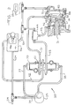
- Fig. 2 is a schematic diagram of a power take-off control apparatus 30 for positioning and maintaining a speed range selection rod 31 for a transmission 32 (shown in fragmentary) in neutral whenever a power take-off mechanism actuator 33 is engaged.
- the apparatus 30 is operated from a suitable fluid source, such as a compressed air line 34 available on many heavy duty trucks.
- the apparatus 30 includes a two position manual control valve 35 for selecting high or low speed gear ranges for the transmission 32 and a two position manual control valve 36 for selectively engaging and disengaging the power take-off mechanism through the actuator 33.
- the control valve 35 has two pilot air lines 37 and 38 connected to opposite ends 39 and 40, respectively, of a shuttle valve 41.
- compressed air flows from the line 34 through the valve 36 and a line 42 to the shuttle valve 41.
- pilot air flows from the line 34 through the valve 35 and the line 37 to move a spool or shuttle (not shown) in the valve 41 toward the end 40 thereby connecting the air line 42 to an air line 43.
- the air line 43 is connected through a shuttle valve 44 and a line 45 to apply compressed air to a chamber 46 formed in a cylinder 47 to one side of a main piston 48 which is attached to the range selecting rod 31.
- the compressed air in the chamber 46 will move the piston 48 to the right, thereby moving the rod 31 to the right to engage the high speed gear range.
- the cylinder 47 includes an auxiliary piston 49 which is shown positioned to the left in Fig. 2, but is normally positioned to the right when the vehicle is in its drive mode. Thus, the piston 48 will move further to the right to abut a stop 50 when the high speed gear range is selected.
- the control valve 36 When the operator desires to operate the power take-off mechanism, the control valve 36 is manually moved to a "PTO" position wherein the air line 34 is connected to a line 54 and the air line 42 to the shuttle valve 41 is vented.
- the air line 54 is connected to the shuttle valve 44, to a chamber 55 in the cylinder 47 and to the power take-off mechanism actuator 33.
- the application of compressed air on the line 54 to the actuator 33 engages the power take-off mechanism.
- the compressed air applied to the chamber 55 moves the auxiliary piston 49 to the left to an extended position where it abuts a stop 56, as shown in Fig. 2.
- the auxiliary piston 49 When the auxiliary piston 49 is in the extended position against the stop 56, an end 57 on the auxiliary piston 49 projects into the chamber 52.
- the control valve 36 also applies compressed air to the shuttle valve 44.
- the shuttle valve 44 passes compressed air from either the line 43 or the line 54 to the chamber 46, while isolating the lines 43 and 54 from each other.
- the auxiliary piston end 57 is located to position the main piston 48 at the intermediate position where the transmission 32 is in neutral. It will be noted that since air from the line 54 is applied to both the chamber 55 and the chamber 46, both chambers will have the same air pressure.
- the auxiliary piston 49 is provided with a larger diameter than the main piston 48.
- the control valve 36 When the operator desires to disengage the power take-off mechanism, the control valve 36 is moved to a position wherein the line 34 is again connected through the line 42 to the shuttle valve 41 and the air line 54 is vented to disengage the actuator 33.
- the shuttle valve 41 will again supply compressed air either on the line 43 for engaging the high speed gear range or on the line 51 for engaging the low speed gear range.
- compressed air is first applied on the line 43, the piston 48 will move to the right and will push the auxiliary piston 49 to the right where it is retracted into the chamber 55 until the piston 48 abuts the stop 50.
- the auxiliary piston 49 presents little resistance to this movement since the chamber 55 will be vented through the line 54 and the control valve 36.
Landscapes
- Engineering & Computer Science (AREA)
- General Engineering & Computer Science (AREA)
- Mechanical Engineering (AREA)
- Chemical & Material Sciences (AREA)
- Combustion & Propulsion (AREA)
- Transportation (AREA)
- Gear-Shifting Mechanisms (AREA)
- Fluid-Pressure Circuits (AREA)
- Arrangement And Mounting Of Devices That Control Transmission Of Motive Force (AREA)
- Arrangement And Driving Of Transmission Devices (AREA)
Applications Claiming Priority (2)
| Application Number | Priority Date | Filing Date | Title |
|---|---|---|---|
| US07/196,918 US4920813A (en) | 1988-05-20 | 1988-05-20 | Power take-off control apparatus |
| US196918 | 2001-04-13 |
Publications (3)
| Publication Number | Publication Date |
|---|---|
| EP0343002A2 true EP0343002A2 (de) | 1989-11-23 |
| EP0343002A3 EP0343002A3 (en) | 1990-12-19 |
| EP0343002B1 EP0343002B1 (de) | 1993-09-29 |
Family
ID=22727282
Family Applications (1)
| Application Number | Title | Priority Date | Filing Date |
|---|---|---|---|
| EP89305092A Expired - Lifetime EP0343002B1 (de) | 1988-05-20 | 1989-05-19 | Zapfwellenantriebssteuerung |
Country Status (8)
| Country | Link |
|---|---|
| US (1) | US4920813A (de) |
| EP (1) | EP0343002B1 (de) |
| JP (1) | JPH0218124A (de) |
| KR (1) | KR960014065B1 (de) |
| BR (1) | BR8902107A (de) |
| CA (1) | CA1317483C (de) |
| DE (1) | DE68909490T2 (de) |
| MX (1) | MX166080B (de) |
Cited By (1)
| Publication number | Priority date | Publication date | Assignee | Title |
|---|---|---|---|---|
| EP1295522A1 (de) * | 2001-09-25 | 2003-03-26 | Tecumseh Products Company | Rückwärtsgangsperre für einen Mäher |
Families Citing this family (13)
| Publication number | Priority date | Publication date | Assignee | Title |
|---|---|---|---|---|
| US5299129A (en) * | 1990-03-26 | 1994-03-29 | Aisin Seiki Kabushiki Kaisha | PTO control apparatus for vehicular automatic transmission |
| US6173225B1 (en) | 1999-04-20 | 2001-01-09 | Case Corporation | Power takeoff control system |
| US6134494A (en) * | 1999-04-20 | 2000-10-17 | Case Corporation | Automatic power takeoff control system |
| US6484600B1 (en) * | 2001-05-09 | 2002-11-26 | Meritor Heavy Vehicle Technology, Llc | Pneumatic three-position shift mechanism with fewer components |
| US7377103B2 (en) * | 2005-07-07 | 2008-05-27 | Ford Global Technologies, Llc | System and method for controlling an engine having a power take off output device |
| WO2008117457A1 (ja) * | 2007-03-27 | 2008-10-02 | Fujitsu Limited | 電子機器 |
| US7861613B2 (en) * | 2007-04-17 | 2011-01-04 | Eaton Corporation | Selector mechanism for dual-clutch transmissions |
| KR101401882B1 (ko) * | 2012-11-28 | 2014-05-29 | 현대다이모스(주) | 동력인출 겸용 2속 변속기 |
| CN104832638B (zh) * | 2015-05-12 | 2017-09-29 | 陕西法士特汽车传动集团有限责任公司 | 一种带副箱变速器高低档转换保护系统及方法 |
| CN106051139A (zh) * | 2016-08-12 | 2016-10-26 | 中国第汽车股份有限公司 | 一种多档变速器副箱气动换档控制系统总成 |
| US10029562B2 (en) | 2016-08-26 | 2018-07-24 | Deere & Company | Power take-off arrangement for work vehicle |
| US10150367B2 (en) | 2016-08-26 | 2018-12-11 | Deere & Company | PTO speed control system for work vehicle |
| CN119508478B (zh) * | 2024-11-22 | 2025-10-31 | 广西合浦县惠来宝机械制造有限公司 | 一种拖拉机气控挂挡装置 |
Family Cites Families (20)
| Publication number | Priority date | Publication date | Assignee | Title |
|---|---|---|---|---|
| US787480A (en) * | 1904-03-01 | 1905-04-18 | Julius R Tanner | Centering-motor. |
| US2095820A (en) * | 1934-08-23 | 1937-10-12 | Gen Electric | Control mechanism for multiple hydraulic gears |
| US2226660A (en) * | 1934-09-10 | 1940-12-31 | Bendix Westinghouse Automotive | Gear shifting mechanism |
| US2575982A (en) * | 1949-04-14 | 1951-11-20 | Westinghouse Air Brake Co | Fluid pressure control mechanism |
| US2902873A (en) * | 1956-10-29 | 1959-09-08 | Gisholt Machine Co | Machine tool headstock control mechanism |
| US2931237A (en) * | 1957-12-02 | 1960-04-05 | Fuller Mfg Co | Automotive device |
| US2944435A (en) * | 1958-03-28 | 1960-07-12 | Hendrickson Mfg Co | Gear shift |
| US2974766A (en) * | 1959-08-24 | 1961-03-14 | Fuller Mfg Co | Automotive device |
| US3033171A (en) * | 1960-09-07 | 1962-05-08 | Sperry Rand Corp | Interlocking means for hydraulic servomotor systems |
| US3059433A (en) * | 1961-02-14 | 1962-10-23 | Hirsch George | Pressure and force multiplying devices |
| US3640146A (en) * | 1970-05-28 | 1972-02-08 | Caterpillar Tractor Co | Hydraulic safety override valve |
| US3958493A (en) * | 1973-08-20 | 1976-05-25 | Tokico Ltd. | Multiple-stage actuating device |
| US3866727A (en) * | 1974-01-18 | 1975-02-18 | Dana Corp | Fluid operated clutch and brake with dashpot |
| US4068537A (en) * | 1976-10-12 | 1978-01-17 | Clark Equipment Company | Shift control system for a multiple input transmission |
| US4149428A (en) * | 1977-02-23 | 1979-04-17 | Otto Mueller | Hydraulic shift mechanism for transfer case with multiple path drive system |
| US4388843A (en) * | 1980-11-21 | 1983-06-21 | Eaton Corporation | Auxiliary transmission neutral positioning and locking control and mechanism |
| US4440037A (en) * | 1981-11-04 | 1984-04-03 | Eaton Corporation | Shift control |
| US4531422A (en) * | 1983-08-29 | 1985-07-30 | Dana Corporation | Transmission shift rod interlock system |
| US4722237A (en) * | 1986-12-12 | 1988-02-02 | Eaton Corporation | Fluid actuated shift bar housing assembly having a centering cylinder therein |
| US4748863A (en) * | 1987-03-17 | 1988-06-07 | Eaton Corporation | Fluid actuated shift bar housing assembly |
-
1988
- 1988-05-20 US US07/196,918 patent/US4920813A/en not_active Expired - Fee Related
-
1989
- 1989-04-14 CA CA000596693A patent/CA1317483C/en not_active Expired - Fee Related
- 1989-05-05 BR BR898902107A patent/BR8902107A/pt not_active IP Right Cessation
- 1989-05-15 MX MX016037A patent/MX166080B/es unknown
- 1989-05-19 EP EP89305092A patent/EP0343002B1/de not_active Expired - Lifetime
- 1989-05-19 JP JP1124621A patent/JPH0218124A/ja active Pending
- 1989-05-19 DE DE89305092T patent/DE68909490T2/de not_active Expired - Fee Related
- 1989-05-19 KR KR1019890006729A patent/KR960014065B1/ko not_active Expired - Lifetime
Cited By (2)
| Publication number | Priority date | Publication date | Assignee | Title |
|---|---|---|---|---|
| EP1295522A1 (de) * | 2001-09-25 | 2003-03-26 | Tecumseh Products Company | Rückwärtsgangsperre für einen Mäher |
| US6625963B2 (en) | 2001-09-25 | 2003-09-30 | Tecumseh Products Company | Reverse lockout feature for a mower |
Also Published As
| Publication number | Publication date |
|---|---|
| US4920813A (en) | 1990-05-01 |
| DE68909490D1 (de) | 1993-11-04 |
| JPH0218124A (ja) | 1990-01-22 |
| EP0343002B1 (de) | 1993-09-29 |
| KR960014065B1 (ko) | 1996-10-12 |
| BR8902107A (pt) | 1989-12-05 |
| MX166080B (es) | 1992-12-17 |
| DE68909490T2 (de) | 1994-01-20 |
| CA1317483C (en) | 1993-05-11 |
| KR890017102A (ko) | 1989-12-15 |
| EP0343002A3 (en) | 1990-12-19 |
Similar Documents
| Publication | Publication Date | Title |
|---|---|---|
| EP0343002B1 (de) | Zapfwellenantriebssteuerung | |
| KR100215701B1 (ko) | 자동차변속기 | |
| EP0052814B1 (de) | Steuerung und Mechanismus zum Verbringen eines Hilfsgetriebes in die Leerlaufstellung und zum Verriegeln in derselben | |
| US3939722A (en) | Arrangement for controlling gear changes in a motor vehicle gear box | |
| US4507736A (en) | Transmission gear shift control system | |
| US5528949A (en) | Three-position shift actuator | |
| US7861612B2 (en) | Transmission range shift control with neutral position lock | |
| AU671070B1 (en) | Dual pressurized fluid actuated shifting mechanism | |
| US4531422A (en) | Transmission shift rod interlock system | |
| DE4125162A1 (de) | Anordnung zur betaetigung einer reibungskupplung eines kraftfahrzeugs, insbesondere eines lastkraftwagens | |
| US3682014A (en) | Down-shifting transmission lock | |
| US6202812B1 (en) | Simplified transfer case shift actuator | |
| US5199314A (en) | Synchronized splitter section protection system/method | |
| US5044216A (en) | Transmission shift control | |
| US5191804A (en) | Dual force fluid actuated shift device | |
| US3944035A (en) | Fluid control system for hydraulically operated transmissions and master clutch | |
| US6339973B1 (en) | Slave valve with integral syncho-saver logic | |
| JPH11270671A (ja) | 変速機用の流体バイアス式弁アセンブリ | |
| US3863518A (en) | Transmission shifting system | |
| US4233860A (en) | Control system for automotive automatic transmission with emergency operation feature | |
| GB2057607A (en) | Arrangement for Blocking a Vehicle Clutch | |
| EP1714055B1 (de) | Verfahren und anordnung zum entgegenwirken von unangemessenen manuellen gangwechseln unter vorbestimmten fahrzeugbedingungen | |
| US5111921A (en) | Park brake sensor and transmission override | |
| US5284065A (en) | Removable overdrive lockout | |
| DE3713586A1 (de) | Elektro-hydraulische steuerung fuer ein automatgetriebe |
Legal Events
| Date | Code | Title | Description |
|---|---|---|---|
| PUAI | Public reference made under article 153(3) epc to a published international application that has entered the european phase |
Free format text: ORIGINAL CODE: 0009012 |
|
| AK | Designated contracting states |
Kind code of ref document: A2 Designated state(s): DE FR GB IT SE |
|
| PUAL | Search report despatched |
Free format text: ORIGINAL CODE: 0009013 |
|
| AK | Designated contracting states |
Kind code of ref document: A3 Designated state(s): DE FR GB IT SE |
|
| 17P | Request for examination filed |
Effective date: 19910610 |
|
| 17Q | First examination report despatched |
Effective date: 19930218 |
|
| ITF | It: translation for a ep patent filed | ||
| GRAA | (expected) grant |
Free format text: ORIGINAL CODE: 0009210 |
|
| AK | Designated contracting states |
Kind code of ref document: B1 Designated state(s): DE FR GB IT SE |
|
| REF | Corresponds to: |
Ref document number: 68909490 Country of ref document: DE Date of ref document: 19931104 |
|
| ET | Fr: translation filed | ||
| PLBE | No opposition filed within time limit |
Free format text: ORIGINAL CODE: 0009261 |
|
| STAA | Information on the status of an ep patent application or granted ep patent |
Free format text: STATUS: NO OPPOSITION FILED WITHIN TIME LIMIT |
|
| 26N | No opposition filed | ||
| EAL | Se: european patent in force in sweden |
Ref document number: 89305092.2 |
|
| PGFP | Annual fee paid to national office [announced via postgrant information from national office to epo] |
Ref country code: GB Payment date: 19950407 Year of fee payment: 7 |
|
| PGFP | Annual fee paid to national office [announced via postgrant information from national office to epo] |
Ref country code: SE Payment date: 19950424 Year of fee payment: 7 |
|
| PGFP | Annual fee paid to national office [announced via postgrant information from national office to epo] |
Ref country code: FR Payment date: 19950517 Year of fee payment: 7 |
|
| PGFP | Annual fee paid to national office [announced via postgrant information from national office to epo] |
Ref country code: DE Payment date: 19950531 Year of fee payment: 7 |
|
| PG25 | Lapsed in a contracting state [announced via postgrant information from national office to epo] |
Ref country code: GB Effective date: 19960519 |
|
| PG25 | Lapsed in a contracting state [announced via postgrant information from national office to epo] |
Ref country code: SE Effective date: 19960520 |
|
| GBPC | Gb: european patent ceased through non-payment of renewal fee |
Effective date: 19960519 |
|
| PG25 | Lapsed in a contracting state [announced via postgrant information from national office to epo] |
Ref country code: FR Effective date: 19970131 |
|
| PG25 | Lapsed in a contracting state [announced via postgrant information from national office to epo] |
Ref country code: DE Effective date: 19970201 |
|
| EUG | Se: european patent has lapsed |
Ref document number: 89305092.2 |
|
| REG | Reference to a national code |
Ref country code: FR Ref legal event code: ST |
|
| PG25 | Lapsed in a contracting state [announced via postgrant information from national office to epo] |
Ref country code: IT Free format text: LAPSE BECAUSE OF NON-PAYMENT OF DUE FEES;WARNING: LAPSES OF ITALIAN PATENTS WITH EFFECTIVE DATE BEFORE 2007 MAY HAVE OCCURRED AT ANY TIME BEFORE 2007. THE CORRECT EFFECTIVE DATE MAY BE DIFFERENT FROM THE ONE RECORDED. Effective date: 20050519 |