EP0342877A2 - Druckwechseladsorptionsverfahren zur Gastrennung - Google Patents
Druckwechseladsorptionsverfahren zur Gastrennung Download PDFInfo
- Publication number
- EP0342877A2 EP0342877A2 EP89304844A EP89304844A EP0342877A2 EP 0342877 A2 EP0342877 A2 EP 0342877A2 EP 89304844 A EP89304844 A EP 89304844A EP 89304844 A EP89304844 A EP 89304844A EP 0342877 A2 EP0342877 A2 EP 0342877A2
- Authority
- EP
- European Patent Office
- Prior art keywords
- gas
- cylinder
- valve
- column
- pressure
- Prior art date
- Legal status (The legal status is an assumption and is not a legal conclusion. Google has not performed a legal analysis and makes no representation as to the accuracy of the status listed.)
- Withdrawn
Links
Images


Classifications
-
- B—PERFORMING OPERATIONS; TRANSPORTING
- B01—PHYSICAL OR CHEMICAL PROCESSES OR APPARATUS IN GENERAL
- B01D—SEPARATION
- B01D53/00—Separation of gases or vapours; Recovering vapours of volatile solvents from gases; Chemical or biological purification of waste gases, e.g. engine exhaust gases, smoke, fumes, flue gases, aerosols
- B01D53/02—Separation of gases or vapours; Recovering vapours of volatile solvents from gases; Chemical or biological purification of waste gases, e.g. engine exhaust gases, smoke, fumes, flue gases, aerosols by adsorption, e.g. preparative gas chromatography
- B01D53/04—Separation of gases or vapours; Recovering vapours of volatile solvents from gases; Chemical or biological purification of waste gases, e.g. engine exhaust gases, smoke, fumes, flue gases, aerosols by adsorption, e.g. preparative gas chromatography with stationary adsorbents
- B01D53/047—Pressure swing adsorption
-
- B—PERFORMING OPERATIONS; TRANSPORTING
- B01—PHYSICAL OR CHEMICAL PROCESSES OR APPARATUS IN GENERAL
- B01D—SEPARATION
- B01D2253/00—Adsorbents used in seperation treatment of gases and vapours
- B01D2253/10—Inorganic adsorbents
- B01D2253/104—Alumina
-
- B—PERFORMING OPERATIONS; TRANSPORTING
- B01—PHYSICAL OR CHEMICAL PROCESSES OR APPARATUS IN GENERAL
- B01D—SEPARATION
- B01D2253/00—Adsorbents used in seperation treatment of gases and vapours
- B01D2253/10—Inorganic adsorbents
- B01D2253/106—Silica or silicates
- B01D2253/108—Zeolites
-
- B—PERFORMING OPERATIONS; TRANSPORTING
- B01—PHYSICAL OR CHEMICAL PROCESSES OR APPARATUS IN GENERAL
- B01D—SEPARATION
- B01D2253/00—Adsorbents used in seperation treatment of gases and vapours
- B01D2253/10—Inorganic adsorbents
- B01D2253/116—Molecular sieves other than zeolites
-
- B—PERFORMING OPERATIONS; TRANSPORTING
- B01—PHYSICAL OR CHEMICAL PROCESSES OR APPARATUS IN GENERAL
- B01D—SEPARATION
- B01D2253/00—Adsorbents used in seperation treatment of gases and vapours
- B01D2253/25—Coated, impregnated or composite adsorbents
-
- B—PERFORMING OPERATIONS; TRANSPORTING
- B01—PHYSICAL OR CHEMICAL PROCESSES OR APPARATUS IN GENERAL
- B01D—SEPARATION
- B01D2253/00—Adsorbents used in seperation treatment of gases and vapours
- B01D2253/30—Physical properties of adsorbents
- B01D2253/302—Dimensions
- B01D2253/304—Linear dimensions, e.g. particle shape, diameter
-
- B—PERFORMING OPERATIONS; TRANSPORTING
- B01—PHYSICAL OR CHEMICAL PROCESSES OR APPARATUS IN GENERAL
- B01D—SEPARATION
- B01D2256/00—Main component in the product gas stream after treatment
- B01D2256/10—Nitrogen
-
- B—PERFORMING OPERATIONS; TRANSPORTING
- B01—PHYSICAL OR CHEMICAL PROCESSES OR APPARATUS IN GENERAL
- B01D—SEPARATION
- B01D2256/00—Main component in the product gas stream after treatment
- B01D2256/12—Oxygen
-
- B—PERFORMING OPERATIONS; TRANSPORTING
- B01—PHYSICAL OR CHEMICAL PROCESSES OR APPARATUS IN GENERAL
- B01D—SEPARATION
- B01D2257/00—Components to be removed
- B01D2257/10—Single element gases other than halogens
- B01D2257/102—Nitrogen
-
- B—PERFORMING OPERATIONS; TRANSPORTING
- B01—PHYSICAL OR CHEMICAL PROCESSES OR APPARATUS IN GENERAL
- B01D—SEPARATION
- B01D2257/00—Components to be removed
- B01D2257/10—Single element gases other than halogens
- B01D2257/104—Oxygen
-
- B—PERFORMING OPERATIONS; TRANSPORTING
- B01—PHYSICAL OR CHEMICAL PROCESSES OR APPARATUS IN GENERAL
- B01D—SEPARATION
- B01D2259/00—Type of treatment
- B01D2259/40—Further details for adsorption processes and devices
- B01D2259/40007—Controlling pressure or temperature swing adsorption
-
- B—PERFORMING OPERATIONS; TRANSPORTING
- B01—PHYSICAL OR CHEMICAL PROCESSES OR APPARATUS IN GENERAL
- B01D—SEPARATION
- B01D2259/00—Type of treatment
- B01D2259/40—Further details for adsorption processes and devices
- B01D2259/40011—Methods relating to the process cycle in pressure or temperature swing adsorption
- B01D2259/40043—Purging
- B01D2259/4005—Nature of purge gas
- B01D2259/40052—Recycled product or process gas
-
- B—PERFORMING OPERATIONS; TRANSPORTING
- B01—PHYSICAL OR CHEMICAL PROCESSES OR APPARATUS IN GENERAL
- B01D—SEPARATION
- B01D2259/00—Type of treatment
- B01D2259/40—Further details for adsorption processes and devices
- B01D2259/40011—Methods relating to the process cycle in pressure or temperature swing adsorption
- B01D2259/40077—Direction of flow
- B01D2259/40081—Counter-current
-
- B—PERFORMING OPERATIONS; TRANSPORTING
- B01—PHYSICAL OR CHEMICAL PROCESSES OR APPARATUS IN GENERAL
- B01D—SEPARATION
- B01D2259/00—Type of treatment
- B01D2259/40—Further details for adsorption processes and devices
- B01D2259/401—Further details for adsorption processes and devices using a single bed
-
- B—PERFORMING OPERATIONS; TRANSPORTING
- B01—PHYSICAL OR CHEMICAL PROCESSES OR APPARATUS IN GENERAL
- B01D—SEPARATION
- B01D2259/00—Type of treatment
- B01D2259/40—Further details for adsorption processes and devices
- B01D2259/402—Further details for adsorption processes and devices using two beds
-
- B—PERFORMING OPERATIONS; TRANSPORTING
- B01—PHYSICAL OR CHEMICAL PROCESSES OR APPARATUS IN GENERAL
- B01D—SEPARATION
- B01D53/00—Separation of gases or vapours; Recovering vapours of volatile solvents from gases; Chemical or biological purification of waste gases, e.g. engine exhaust gases, smoke, fumes, flue gases, aerosols
- B01D53/02—Separation of gases or vapours; Recovering vapours of volatile solvents from gases; Chemical or biological purification of waste gases, e.g. engine exhaust gases, smoke, fumes, flue gases, aerosols by adsorption, e.g. preparative gas chromatography
- B01D53/04—Separation of gases or vapours; Recovering vapours of volatile solvents from gases; Chemical or biological purification of waste gases, e.g. engine exhaust gases, smoke, fumes, flue gases, aerosols by adsorption, e.g. preparative gas chromatography with stationary adsorbents
- B01D53/0407—Constructional details of adsorbing systems
- B01D53/0446—Means for feeding or distributing gases
-
- B—PERFORMING OPERATIONS; TRANSPORTING
- B01—PHYSICAL OR CHEMICAL PROCESSES OR APPARATUS IN GENERAL
- B01D—SEPARATION
- B01D53/00—Separation of gases or vapours; Recovering vapours of volatile solvents from gases; Chemical or biological purification of waste gases, e.g. engine exhaust gases, smoke, fumes, flue gases, aerosols
- B01D53/02—Separation of gases or vapours; Recovering vapours of volatile solvents from gases; Chemical or biological purification of waste gases, e.g. engine exhaust gases, smoke, fumes, flue gases, aerosols by adsorption, e.g. preparative gas chromatography
- B01D53/04—Separation of gases or vapours; Recovering vapours of volatile solvents from gases; Chemical or biological purification of waste gases, e.g. engine exhaust gases, smoke, fumes, flue gases, aerosols by adsorption, e.g. preparative gas chromatography with stationary adsorbents
- B01D53/047—Pressure swing adsorption
- B01D53/0473—Rapid pressure swing adsorption
-
- B—PERFORMING OPERATIONS; TRANSPORTING
- B01—PHYSICAL OR CHEMICAL PROCESSES OR APPARATUS IN GENERAL
- B01D—SEPARATION
- B01D53/00—Separation of gases or vapours; Recovering vapours of volatile solvents from gases; Chemical or biological purification of waste gases, e.g. engine exhaust gases, smoke, fumes, flue gases, aerosols
- B01D53/02—Separation of gases or vapours; Recovering vapours of volatile solvents from gases; Chemical or biological purification of waste gases, e.g. engine exhaust gases, smoke, fumes, flue gases, aerosols by adsorption, e.g. preparative gas chromatography
- B01D53/04—Separation of gases or vapours; Recovering vapours of volatile solvents from gases; Chemical or biological purification of waste gases, e.g. engine exhaust gases, smoke, fumes, flue gases, aerosols by adsorption, e.g. preparative gas chromatography with stationary adsorbents
- B01D53/047—Pressure swing adsorption
- B01D53/0476—Vacuum pressure swing adsorption
-
- B—PERFORMING OPERATIONS; TRANSPORTING
- B01—PHYSICAL OR CHEMICAL PROCESSES OR APPARATUS IN GENERAL
- B01D—SEPARATION
- B01D53/00—Separation of gases or vapours; Recovering vapours of volatile solvents from gases; Chemical or biological purification of waste gases, e.g. engine exhaust gases, smoke, fumes, flue gases, aerosols
- B01D53/02—Separation of gases or vapours; Recovering vapours of volatile solvents from gases; Chemical or biological purification of waste gases, e.g. engine exhaust gases, smoke, fumes, flue gases, aerosols by adsorption, e.g. preparative gas chromatography
- B01D53/04—Separation of gases or vapours; Recovering vapours of volatile solvents from gases; Chemical or biological purification of waste gases, e.g. engine exhaust gases, smoke, fumes, flue gases, aerosols by adsorption, e.g. preparative gas chromatography with stationary adsorbents
- B01D53/047—Pressure swing adsorption
- B01D53/053—Pressure swing adsorption with storage or buffer vessel
Definitions
- the present invention relates to an improvement of a pressure swing adsorption process which is one of known processes for separating a desired gas from a gas mixture such as air.
- a separation technique of gas mixtures in which separation of air is representative has been developed.
- a distillation process e.g., low temperature separation process
- an adsorption separation process e.g., adsorption separation process
- a membrane separation process e.g., adsorption separation process
- PSA process pressure swing adsorption process
- a desired product gas can be separated from a stock gas (feed gas) within a short time from the beginning of the operation of the process and can be obtained with a high purity at a relatively high yield, as compared with the low temperature separation process and other processes, and has been employed for recovery of various gases from gas mixtures.
- the pressure swing adsorption process is shown, for example. in United States Patents No. 3,430,418 and No. 3,564,816.
- a typical PSA process generally comprises the following steps:
- Steps (1) through (5) are performed for separation of the desired gas, and Steps (6) and (7) are performed for regeneration of the column.
- Fig. 1 illustrates a known two cylinder system used for performing a pressure swing adsorption process.
- Each of two cylinders 11, 11a contains therein an adsorption column of an adsorbent.
- the cylinders 11, 11a have, respectively, inlets 12, 12a for a gas mixture to be separated and outlets 13, 13a for collecting a desired gas having been separated from the gas mixture in the respective cylinder.
- the inlets 12, 12a are connected to a source of gas mixture 14 by pipe lines via valves 15, 15a, respectively.
- the inlets 12, 12a are additionally connected to each other through a pipe line via valves 16, 16a. Between the valves 16, 16a, the pipe line has a waste gas line 17.
- the outlets 13, 13a are connected to a product gas resorvoir 18 by pipe lines via valves 19, 19a, respectively.
- the outlets 13, 13a are additionally connected to each other through a pipe line via valves 20, 20a.
- the pipe line has a branch pipe line which is connected to the product gas reservoir 18 via a pressure controlling valve 21.
- the pressure swing adsorption process is performed in the system of Fig. 1 in the following manner.
- a gas mixture (e.g., air and industrially produced gas mixture) is continuously supplied under pressure from the source of gas mixture 14 into the cylinder 11 from the inlet 12.
- the supply of the gas mixture is performed by opening the valve 15.
- the valves 15a, 16, 19, 20 are all closed.
- the gas mixture continuously introduced into the cylinder 11 advances forwards during which one or more gas components other than a desired gas component is adsorbed by the adsorbent of the adsorption column to form an adsorbed gas zone.
- the front of the adsorbed gas zone moves forwards in the cylinder 11.
- the valve 19 is opened to discharge the desired gas from of the outlet 13 to direct it to the product gas reservoir 18. Then, just before the front of the adsorbed gas zone reaches the end of the column, the valve 15 is closed to terminate the supply of the gas mixture into the cylinder, and simultaneously, the valve 19 is closed.
- the absorption column regeneration process is started.
- the valve 12 is first opened to discharge the pressurized gas remaining in the cylinder 11 through the waste gas line 17.
- the waste gas line 17 may be connected to a vacuum system (not shown) to more efficiently discharge the pressurized gas in the cylinder 11.
- the desorption of the adsorbed gas component is then performed using a portion of the product gas (the desired gas component) previously collected in the product gas reservoir 18.
- a portion of the product gas is continuously returned into the cylinder 11 by opening the valve 20, placing the pressure control valve 21 under an operative condition.
- returned product gas advances in the cylinder 11, desorbing the adsorbed gas component, and is discharged from the waste gas line 17.
- the gas may be discharged more efficiently by means of a vacuum system which may be provided to the waste gas line 17.
- the supply of the product gas is continued until most of the adsorbed gas component is desorbed and discharged from the waste gas line 17.
- the above procedure for desorbing the adsorbed gas component using a portion of the product gas is named a purging procedure. By a series of these procedures, the column regeneration process is complete.
- the set of the gas separation process and the column regeneration process is repeated to produce a required amount of the desired gas.
- a portion of the product gas may be returned to the cylinder for so controlling the pressure in the cylinder as to avoid abrupt change of the pressure.
- the column regeneration process is performed in the cylinder 11a.
- the gas separation process is performed in the cylinder 11a.
- the product gas i.e., desired gas component
- the pressure in the cylinder varies within a wide range to the extent from several Torr to several ten kg/cm2G.
- Each step of the pressure swing adsorption process is carried out from several seconds to several minutes.
- a set of valves provided to the system are opened and closed automatically according to a predetermined program.
- One cycle of the pressure swing adsorption process namely, one set of the gas separation process and the column regeneration process is performed from several ten seconds and several ten minutes. Therefore, the pressure change in the cylinder is apt to occur abruptly within a very short time.
- the abrupt change (or variation) of the pressure in the cylinder is apt to cause certain troubles.
- a neatly arranged adsorbent of the adsorption column may be disarranged, and the gas flows unsteadily in the cylinder. For example, a portion of the gas flows along the inner wall of the cylinder with insufficient contact with the adsorbent. Otherwise, a portion of the gas flows through a space formed by the disarrangement of the adsorbent with insufficient contact with the adsorbent. Such insufficient contact of the flowing gas with the adsorbent causes poor adsorption or poor desorption. Thus, efficiency of the gas separation process is adversely affected.
- the improved pressure swing adsorption process of the present invention can be performed using the conventional system of Fig. 1 in the following manner.
- a gas mixture e.g., air or an industrially produced gas mixture such as a methanol decomposition gas comprising hydrogen, carbon dioxide, carbon monoxide and water
- a gas mixture e.g., air or an industrially produced gas mixture such as a methanol decomposition gas comprising hydrogen, carbon dioxide, carbon monoxide and water
- nitrogen or oxygen can be selectively collected using an appropriate adsorbent.
- a number of such appropriate adsorbents are known for trapping oxygen, nitrogen, or other gas.
- a molecular-sieve carbon can be employed as an adsorbent for trapping oxygen.
- a certain molecular sieve such as MS-5A can be employed as an adsorbent for trapping nitrogen.
- the supply of the gas mixture is performed by opening the valve 15. During this procedure, the valves 15a, 16, 19, 20 are closed.
- the gas mixture is preferably supplied to the cylinder at an intermittently varying rate (i.e, velocity) by changing the position of the valve 15 between the opening position and the closing position at a short interval, that is, in the form of a pulse action.
- a set of the valve opening action and the valve closing action is preferably repeated 2 to 5 times.
- the period of opening the valve preferably ranges from 0.01 to 5 seconds, more preferably 0.05 to 3 seconds, per one opening procedure.
- the period of closing the valve preferably ranges from 0.1 to 2 seconds, more preferably 0.5 to 1.5 seconds, per one closing procedure.
- the period for opening and closing for each valve fan be set at a fixed value or to vary at each time periodically or non-periodically. It is preferred to perform the pulse action more quickly (namely, at a shorter interval) in the initial stage of this step, because the pressure variation generally takes place very drastically at the intial stage.
- the pulse action for supplying the gas mixture into the cylinder the gas mixture very smoothly advances forwards in the cylinder 11 with steady pulse contact with the adsorbent.
- one or more gas components other than a desired gas component is adsorbed by the adsorbent of the adsorption column to form an adsorbed gas zone.
- the front of the adsorbed gas zone moves forwards in the cylinder 11.
- the valve 19 is opened to collect the desired gas component from of the outlet 13 to direct it to the product gas reservoir 18.
- the desired gas component in the cylinder 11 is easily taken out, because the desired gas component is kept in the cylinder at an elevated pressure.
- Such intermittent varying rate of the desired gas collection can be accomplished by automatically operating the valve 19 in the same manner as described for the valve 15 used for the gas mixture supply into the cylinder 11.
- the valve 15 When the pressure of the gas mixture in the cylinder 11 reaches a predetermined maximum level (generally set at a pressure of lower than 6 kg/cm2), the valve 15 is closed to terminate the supply of the gas mixture into the cylinder 11.
- the time for termination of the gas mixture supply is previously determined under the condition that the front of the adsorbed gas zone still does not reach the end of the adsorption column at the time of the termination of gas mixture supply.
- the valve 19 Simultaneously with the termination of the as supply, the valve 19 is closed to terminate collection of the desired gas from the cylinder 11.
- the valve 16 is first opened to discharge the pressurized gas remaining in the cylinder 11 through the waste gas line 17. As is apparent from the above procedure, the gas remaining in the cylinder 11 is still kept under high pressure. There strictlyfore, if the valve 16 is simply opened in the convention al manner to allow the remaining gas flowing out at once, unfavorable irregular flow of the gas likely occurs. Accordingly, it is preferred still in this step to discharge the remaining gas at an intermittently varying rate by automatically operating the valve 16 in the same manner as described for the valve 15 used for the gas mixture supply into the cylinder 11.
- the waste gas line 17 may be connected, as described abvoe to a vacuum system to more efficiently discharge the pressurized gas in the cylinder 11.
- the vacuum system is generally operated after spontaneous discharge of the remaining gas terminates.
- the adsorbed gas component is then desorbed using a portion of the product gas (the desired gas component) previously collected in the product gas reservoir 18.
- a portion of the product gas should be supplied into the cylinder 11 at an intermittently varying rate, for example, by opening and closing the valve 20, at a short interval, that is, by an opening-closing action in a pulse mode, while opening the pressure control valve 21.
- the period required for the supply to the product gas into the cylinder generally is set to be not longer than one minute. Within the supply period, a set of the valve opening action and the valve closing action is preferably repeated 2 to 5 times.
- the period of opening the valve preferably ranges from 0.01 to 5 seconds, more preferably 0.05 to 3 seconds, per one opening procedure.
- the period of closing the valve preferably ranges from 0.1 to 2 seconds, more preferably 0.5 to 1.5 seconds, per one closing procedure.
- the period of the valve opening and the valve closing can be set for each valve at a fixed value or to vary at each time periodically or non-periodically. It is preferred to perform the pulse action more quickly (namely, at a shorter interval) in the initial stage of this step, because the pressure variation generally takes place very drastically at the intial stage.
- the set of the gas separation process and the column regeneration process is repeated to produce a required amount of the desired gas.
- Fig. 2 is a schematic flowchart showing a simple system using a single column for separating nitrogen gas from air.
- the system comprises a cylinder 31 which contains an adsorption column of an adsorbent such as molecular-sieve carbon (MSC), a pump P for compression and pressure reduction, a feed valve 32 for feeding a gas mixture (air), a valve 33 for directing air into the cylinder 31, a valve 34 for directing a separated product gas (N2) to a reservoir 38, a valve 35 for discharging a gas in the cylinder, a valve 36 for directing waste gas (O2) to outside, a purge valve 37, a reservoir 38 for product gas, a reservoir 39 for feed gas, a valve 40 (manual or constant-flow valve) for taking product gas out of the system, pressure sensors S1 and S2, and conduits 50, 51, 52 and 53.
- the valves 32 to 37 are automatic valves.
- the system illustrarted in Fig. 2 can be modified to give a more compact one.
- the reservoir 39 for feed gas may be omitted to connect the pump P directly to the valve 33.
- the reservoir 38 for product gas may be an elastic vessel or bag such as a diaphragm.
- another vacuum pump may be joined to the valve 35 to use the pump P only for supplying a gas mixture in order to enhance the purity of product gas.
- a valve 41 may be placed on the conduit 52 in order to introduce a feed air directly to the cylinder 31 under atmospheric pressure.
- Product N2 gas is produced from feed air in the re peated cycle of the gas separation process and the column generation (discharge and desorption) process as follows.
- the feed air is supplied through the air-feed valve 32 and the pump P to the air reservoir 39, which is kept at almost constant pressure.
- the valve 33 is opened and closed intermittently according to a previously determined make-and-break (on-off) pattern of valve (called as "valve sequence''). Air in an amount predetermined for the valve sequence is supplied through the conduits 50 and 52 to the adsorption column cylinder 31. and the pressure within the cylinder becomes the predetermined highest pressure.
- valve 34 is preferably opened and closed intermittently according to the valve sequence to taken out the separated N2 gas from the cylinder31 through the conduit 53 to the product gas reservoir 38.
- valves 32, 33 and 34 are closed, while the valves 35 and 36 are opened.
- unnecessary O2 gas in the cylinder 31 passes through the conduit 51 and the pump P to run away in air through the valve 36, and the pressure of the cylinder reaches an atmospheric pressure.
- the valve 37 is opened and closed intermittently and a portion of the product gas in the reservoir 38 is allowed to flow countercurrently (flow opposite to the movement of air in the gas separation process) through the column in the cylinder 31, whereby O2 gas having been adsorbed in the column is desorbed and purged away.
- the interior of the cylinder may be processed to reach more reduced pressure using a vacuum system, or the supply of the purge gas (i.e., product gas) and the operaton of the vacuum pump can be alternately performed.
- the feed gas may be introduced into the cylinder after a portion of purge gas is once introduced in the cylinder. The combination of these procedures is effective to perform the desorption of O2 gas efficiently to enhance the purity of the finally obtained product gas.
- air may be introduced directly from the valve 41 into the cylinder 31 according to the valve sequence without using the pump P when the lowest pressure in the cylinder is below the atmospheric pressure.
- the upper stream side of the valve 41 is always at constant atmospheric pressure.
- the pressure in the cylinder may be first increased to reach an atmospheric pressure by means of the valve 41 in the initial stage of the introduction of feed air and then further increased to the highest pressure by means of the valve 33, whereby control of the introduction of feed air can be made with increased precision.
- Fig. 3 is a graph in which pressure change in the cylinder is plotted as ordinate and time change of one cycle as abscissa (i.e., a graph of pressure sequence).
- the pressure of the column is increased stepwise to the highest pressure by three times open-and-close action (indicated by a1, a2 and a3) of the valve 33 for introducing the feed gas.
- the pressure in the cylinder is then reduced stepwise by twice open-and-close action (indicated by n1 and n2) of the valve 34 for taking out the product gas from the cylinder.
- Fig. 4 is a graph showing actuating operations of valves to give the pressure sequence of Fig. 3.
- Fig. 5 is a partially enlarged graph of Fig. 4.
- t a1 , t a2 and t a3 mean the starting times of the first valve-opening action a1.
- ⁇ t a1 , ⁇ t a2 and ⁇ t a3 mean the first valve-opening time (sec.) (i.e., pulse time), the second valve-opening time and the third valve-opening time, respectively.
- ⁇ t n1 , ⁇ t n2 , ⁇ t g1 and ⁇ t g2 has a meaning similar to the above.
- ⁇ t z1 and ⁇ t z2 mean valve-closing time (sec.), that is, waiting time (i.e., pause time).
- the preferred degrees of increase of pressure in a1, a2 and a3 are not usually equal to each other. These degrees depends upon various parameters such as pressure in the cylinder just before the time of opening valve, the composition of gas mixtures, type and particle size of adsorbent, shape of cylinder, temperature and kind of automatic valve, and can be determined by experiments.
- the relationship between the pressure change in the cylinder from the lowest pressure P O to the highest pressure P h (P3) caused by the three times valve action (a1, a2 and a3) and the amount of introduced gas (amount of gas influx, Q1, Q2 and Q3) can be described approximately as follows.
- the pressure change (in terms of absolute pressure basis) caused by the valve action and the amount of introduced gas (influx) are as follows.
- the pulse time ⁇ t a1 , ⁇ t a2 and ⁇ t a3 are approximately detemined based on nature of valve and the formulas (1) and (2). However, the accurate pulse time should be determined by experiments.
- K is an experimentally determined constant (K > 1).
- the flow rate of gas for each pulse at the valve which directly controls quantity and quality of gas to the adsorbent in the cylinder can be also estimated from flow rate including parameters such as pulse time, CV value of each valve, pressure difference between the upper and lower streams and physical properties of gas.
- parameters such as pulse time, CV value of each valve, pressure difference between the upper and lower streams and physical properties of gas.
- the adsorption column may comprise two adsorption columns arranged in series.
- Fig. 6 is a schematic view showing an arrangement of two adsorption columns in respective cylinders.
- two adsorption columns A and B are arranged in series in the flow direction (A ⁇ B) and a means 62 for controlling flow rate, which is usually an automatic valve, is placed between the columns A and B.
- a means 62 for controlling flow rate which is usually an automatic valve, is placed between the columns A and B.
- an automatic valve 61 for directing feed gas (air) 60 to the column A is attached and at the other end of the column B, an automatic valve 63 for taking out product N2 gas 64 from the column B is attached.
- Feed air 60 is introduced into the adsorption column A by means of the intermittent open-and-close action of the valve 61.
- the feed air is intensely swung among the adsorbent particles in the column A and thereby, renewal of surfaces among the adsorbent particles proceeds and density of an adsorbate in gas phase is lowered within a short time.
- a zone of adsorbed gas i.e., adsorbate of O2 gas
- the flow-rate control means (valve) 62 is opened to transfer the air retained in the column A to the column B.
- the air is transferred at almost a constant flow rate by using a flow-rate control valve.
- suitable density gradient of the adsorbate is formed and thereby, the air in which N2 density has been enhanced in the column A is further enhanced in N2 density and finally becomes N2 gas at a high purity, which is taken out through the valve 63.
- the feed air is subjected to rough separation treatment in the column A and to accurate separation treatment in the column B, so that a product gas of high purity can be obtained.
- the inlet-side end of the column A is kept under reduced pressure and the valve 61 is opened to release O2 gas remaining in the column A out of the system.
- the flow-rate control valve 62 is intermittently opened and closed and thereby, the air in which the major component is N2 gas in the column B is released (i.e., countercurrently purge) in the column A to accelerate desorption of O2 gas from the column A.
- the valve 63 is intermittently opened and closed to purge the column B countercurrently with product N2 gas and thereby, desorption of O2 gas in the column B is accelerated.
- the adsorbent columns A and B can have any structure, so far as an adsorbed gas zone is formed independently in each column.
- Two columns may be included in one adsorption column and the means for controlling flow rate may be an orifice.
- Fig. 7 shows another embodiment in which two columns A and B are integrated into one column and an orifice 72 is provided in a position to form a partition between the columns A and B.
- valves for introducing feed gas may be attached to the inlet-side end of the column A and the feed gas can be introduced thereto by alternate action of these valves, in order to promote the surface renewal among the adsorbent particles in the column A.
- the column A preferably is formed of the adsorbent in such a way that volume of contact with gas is large with dead volume being as small as possible.
- the column A preferably has a large sectional area so that air flow rapidly reaches the whole adsorbent. Since the large sectional area of the column brings about increase of dead volume, the column is required to design in consideration of these points.
- Each of the columns A and B preferably has a shape of coaxial cylinder.
- a volume ratio of the columns A and B is preferably in the range of 1.0 : 0.2 to 1.0 : 1.2 (A : B) and a ratio of height and diameter of the column B is preferably in the range of 10 : 1 to 2 : 1 (height : diameter).
- molecular-sieve carbon (MSC) of an adsorbent for O2 gas is usually employed.
- a particle size of the adsorbent is preferably in the range of 20 to 100 mesh.
- a part of the column A near the inlet end may be formed of an adsorbent such as silica gel or activated alumina as a drying agent.
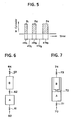
- Fig. 8 is a schematic flowsheet showing another system with one column for separating oxygen gas from air.
- Fig. 9 is a graph showing pressure sequence in one cycle (cycle time : T sec.) and
- Fig. 10 is a diagram showing typical valve sequence in one cycle.
- the system of Fig. 8 comprises a cylinder 80 of an adsorption column, a pump P for compression and pressure reduction, a reservoir R for product gas (O2), a feed gas mixture (air) 81, a valve 82 for feeding the gas, a valve 83 for directing the feed gas to the column 80, a valve 84 for directing product gas to the reservoir R, a product gas 85, a purge valve 87, a valve 88 for discharging a gas from the cylinder, a valve 89 for directing waste gas (N2) to outside, a waste gas 90, a valve 91 which is in direct contact with an atmospheric air and directs the feed gas to the cylinder 80, and a valve 86 (manual valve) for taking product gas out of the system.
- the valves other than the valve 86 are automatic valves.
- Product O2 gas is produced from the feed air in the repeated cycle of the gas separation process and the column regeneration process in the following manner.
- valve 91 is intermittently opened and closed three times (indicated by a 1, a 2 and a 3 in Figs. 9 and 10) to introduce the feed air into the cylinder 80.
- the pump P is actuated and the valve 82 is opened and thereby, the feed air 81 is introduced and reaches the valve 83 through the pump P.
- the valve 83 is then opened (indicated by a 4) to supply the feed air to the column in the cylinder 80, and the pressure in the cylinder 80 is increased. Feed gas (air) 81 is further supplied, and the pressure in the cylinder 80 is further increased and reaches the predetermined pressure.
- valve 84 is started in such a mode to open and close intermittently (indicated by O 1 and O 2) and thereby, unadsorbed gas (O2 gas) is taken out from the cylinder 80 and stored in the product gas reser voir R as a product gas 85.
- unadsorbed gas O2 gas
- the product gas 85 stored in the reservoir R is taken out of the system through the valve 86.
- the supply of the feed gas is then terminated.
- the pump P is so actuated that the conduit connected to the pump P is placed under reduced pressure, and then the valves 88, 89 are opened.
- these valves are opened, a portion of N2 gas trapped in the column is desorbed and flows through the valve 88, the pump P and the valve 89 to run out as waste gas 90.
- the pressure in the cylinder 80 is reduced first rapidly and then slowly.
- valve 87 is intermittently opened and closed three times (indicated by g 1, g 2 and g 3) to return a portion of the product gas 85 into the cylinder 80.
- the returned product gas is rapidly expanded in the cylinder having been placed under reduced pressure, and flows downward, desorbing N2 from the absorbent, to run out from the valve 89 as waste gas.
- the adsorbed N2 is removed, and the regeneration of the adsorption column is complete.
- the opened valve 88 may be intermittently closed in association with the pulse action of the purge valve 87.
- the returned product gas is retained in the cylinder for a while and then discharged together with desorbed N2 gas therefrom, so that the desorption of N2 gas can be more efficiently conducted.
- Fig. 11 is a schematic flowsheet showing another system using one adsorption column and two reservoirs.
- the system comprises a cyldiner A having an adsorption column, a feed gas mixture (air) 110, a feed valves 111 and 112 for the feed gas, a valve 113 for directing the feed gas to the cylinder A, a valve 114 for directing product gas (O2) to a reservoir R1 for storing product gas for actual use, a valve 115 for directing product gas to a reservoir R2 for storig product gas to be used for purging, a purge valve 116, a valve 117 for taking out a gas from the cylinder A, a valve 118 for directing waste gas (N2) to outside, waste gas 119, a flow control valve 120, a stop valve 121, a product gas for actual use 122, a pump P for compression and pressure reduction, a pressure indicator S O for the cylinder A, a pressure indicator S1 for the reservoir R1, and a pressure indicator S2 for the reservoir R2.
- Product O2 gas is produced from the feed air in a repeated cycle of the gas separation process and the column regeneration process in the following manner.
- the valve 111 is intermittently opened and closed twice to introduce feed air to the cylinder A whose adsorption column has been already regenerated.
- the valve 112 is opened and thereby, feed air 110 compressed by the pump P reaches the valve 113.
- the valve 113 is opened to supply the feed air 110 to the cylinder A.
- the predetermined amount of feed air is portionwise introduced to the cylinder A.
- the valve 114 Before or after the interior of the cylinder A reaches the predetermined highest pressure (P h ), the valve 114 is intermittently opened and closed according to the fixed valve sequence and thereby, unadsorbed O2 gas (product gas) is taken out of the cylinder A and stored in the reservoir R1 for actual use. Then, the valve 114 is closed and the valve 115 is intermittently opened and closed according to the fixed valve sequence and thereby, another portion of unadsorbed O2 gas is taken out of the cylinder A and stored in the purge-gas reservoir R2. Thus, the product gas is separately stored in two reservoirs by actuating these two valves.
- unadsorbed O2 gas product gas
- the pulse action of the valve 114 is preferably performed before that of the valve 115, but may be performed after the pulse action of the valve 115.
- the product gas stored in the reservoir R1 is continuously taken out of the system as a product gas 122 (for actual use) at constant flow rate through the flow control valve 120 and the stop valve 121.
- the valves 111, 112, 113, 114 and 115 are closed, the pump P is actuated, and the valves 117 and 118 are opened to discharge unnecessary N2 gas adsorbed in the adsorption column in the cylinder A as waste gas 119 from the system through the valve 118.
- the pressure in the cylinder A is reduced from a higher level to almost the lowest level.
- the valve 116 is intermittently opened and closed three times while opeing the valve 117 to purge the adsorption column in the cylinder A with the product gas stored in the purge-gas reservoir R2, so that desorption of retained N2 gas is accelerated.
- the gas reservoir for actual use R1 and the purge-gas reservoir R2 can have any structure.
- the gas reservoir R1 is preferably variable in volume and comprises an elastic vessel from the viewpoint of designing the whole separation system to be compact. Examples of such reservoirs includes a diaphragm tank and a water seal tank.
- the purge-gas reservoir R2 can be in the shape of a hollow cylinder and arranged concentrically with the cylinder A outside thereof.
- Oxygen gas was separated from air using the two-cylinder apparatus shown in Fig. 1 for performing the improved PSA process according to the invention.
- Each of the cylinders for adsorption column had a diameter of 11 cm. and a height of 44 cm. and packed with 3.1 kg. of a molecular sieve (MS-5A) to form an adsorption column.
- All valves except a valve 11 were 3/8-inch type electromagnetic valves having a opening area of 11 mm2. The valve is kept under opening conditions.
- Adsorption was performed at a gauge pressure of 1.2 kg./cm2.
- One cycle for the set of the gas separation proces and the column regeneration process required 36 seconds.
- In the step for purging adsorbed gas using a portion of the collected oxygen was also repeated three times with an opening period of 0.5 second for each time.
- Oxygen gas was separated from air using the same two-cylinder apparatus as in Example 1 for performing the conventional pressure swing adsorption process.
- the yield of recovery of product gas in Example 1 was higher than that in Comparison Example 1.
- the increase of the amount of recovery in Example 1 is considered due to decrease of loss of product gas (collected gas) in the purge step.
- Nitrogen gas was separated from air by using the one-column system shown in Fig. 2 for performing the improved pressure swing process of the invention.
- the cylinder for adsorption column was had a diameter of 3.6 cm. and a height of 45 cm., and the inlet end part of the cylinder was packed with 91 g. of activated alumina and the other part with 204 g. of molecular seive-carbon (MSC) at a particle size of 40 to 80 mesh.
- the valves were all electromagnetic valves in which the valves 34, 37 and 41 were of 1/4-inch type and other valves were of 3/8-inch type.
- the gas separation was performed at an absolute pressure in the range of 0.1 to 1.7 kg./cm2 according to the valve sequence set forth in Table 1.
- cycle time was 30 sec.
- Table 1 Valve Number Valve-opening Time (sec.) 32 0 - 15 33 4 - 15 34 9 - 15 35 15 - 30 36 0 - 4, 15 - 30 37 22 - 22.1, 25 - 25.1, 28 - 28.1 41 0 - 0.1, 1 - 1.1, 2 - 4
- Oxygen gas was separated from air by using the one-column system shown in Fig. 8 for performing the improved pressure swing adsorption process of the invention.
- the cylinder of adsorption column made was made of stainless steel and had a diameter of 3.56 cm. and a height of 42.0 cm.
- the inlet end part of the cylinder was packed with 75 g. of activated alumina and the other part with 300 g. of MS-5A at a particle size of 30 to 60 mesh, which has been subjected to a heat-activation treatment at 280 o C for 10 hr. prior to the use.
- the valves other than the valve 86 of manual one were 1/4-inch type electromagnetic valves.
- the pump P was of 120-watt type for compression and pressure reduction.
- the gas separation was performed according to the valve sequence shown in Fig. 10 and cycle time was 30 sec. which comprises 10 sec. of the adsorption step and 20 sec. of the reproduction step.
- the valve 91 was opened and closed three times to pressurize the interior of the cylinder, that is, opened for pulse time (indicated by a1 in Fig. 10) of 0.1 sec., closed for pause time of 0.9 sec., opened for pulse time (a2) of 0.2 sec., closed for pause time of 0.8 sec., opened for pulse time (a3) of 0.3 sec., and closed for pause time of 0.7 sec. Then, the valve 83 was opened to further pressurize the interior of the cylinder (time (a4) of 7.0 sec.).
- valve 87 was opened and closed three times to purge the adsorption column with a portion of product gas, that is, opened for pulse time (g1) of 0.1 sec., closed for pause time of 1.9 sec., opened for pulse time (g2) of 0.1 sec., closed for pause time of 1.9 sec. and then opened for pulse time (g3) of 0.1 sec.
- Oxygen gas was separated from air in the same manner as described in Example 3 except that the intermittent open-close actions of the valves 91, 83 and 87 were not conducted. That is, these valves were once opened and closed.
- Purity of finally collected O2 gas 60 % (at amount of O2 gas of 60 cc./cycle)
- Purity of finally collected O2 gas 90 % (at amount of O2 gas of 30 cc./cycle)
Landscapes
- Chemical & Material Sciences (AREA)
- Engineering & Computer Science (AREA)
- Analytical Chemistry (AREA)
- General Chemical & Material Sciences (AREA)
- Oil, Petroleum & Natural Gas (AREA)
- Chemical Kinetics & Catalysis (AREA)
- Separation Of Gases By Adsorption (AREA)
- Oxygen, Ozone, And Oxides In General (AREA)
- Hydrogen, Water And Hydrids (AREA)
Applications Claiming Priority (2)
| Application Number | Priority Date | Filing Date | Title |
|---|---|---|---|
| JP63115200A JP2691991B2 (ja) | 1988-05-12 | 1988-05-12 | 気体分離方法 |
| JP115200/88 | 1988-05-12 |
Publications (2)
| Publication Number | Publication Date |
|---|---|
| EP0342877A2 true EP0342877A2 (de) | 1989-11-23 |
| EP0342877A3 EP0342877A3 (de) | 1991-03-27 |
Family
ID=14656833
Family Applications (1)
| Application Number | Title | Priority Date | Filing Date |
|---|---|---|---|
| EP19890304844 Withdrawn EP0342877A3 (de) | 1988-05-12 | 1989-05-12 | Druckwechseladsorptionsverfahren zur Gastrennung |
Country Status (2)
| Country | Link |
|---|---|
| EP (1) | EP0342877A3 (de) |
| JP (1) | JP2691991B2 (de) |
Cited By (6)
| Publication number | Priority date | Publication date | Assignee | Title |
|---|---|---|---|---|
| EP0641591A1 (de) * | 1993-09-07 | 1995-03-08 | Praxair Technology, Inc. | Druckwechseladsorptionsverfahren mit einzigem Bett |
| WO1995021681A1 (en) * | 1994-02-08 | 1995-08-17 | Alberta Research Council | Serial flow pressure swing adsorption process for gas separation |
| US5620501A (en) * | 1995-08-15 | 1997-04-15 | The Boc Group, Inc. | Recovery of trace gases from gas streams |
| EP0873776A3 (de) * | 1997-04-23 | 1998-11-18 | The Boc Group, Inc. | Druckwechseladsorptionsverfahren und -vorrichtung |
| US6344070B1 (en) | 1997-11-01 | 2002-02-05 | Domnick Hunter Ltd | Selective adsorption of components of a gas mixture |
| US6955711B2 (en) | 2001-04-16 | 2005-10-18 | Taiyo Nippon Sanso Corporation | Method and system for separating gas |
Families Citing this family (2)
| Publication number | Priority date | Publication date | Assignee | Title |
|---|---|---|---|---|
| US6887301B2 (en) * | 2003-06-04 | 2005-05-03 | H2Gen Innovations, Inc. | Flow control in pressure swing adsorption systems |
| JP5537208B2 (ja) | 2010-03-24 | 2014-07-02 | 大阪瓦斯株式会社 | 可燃性ガス濃縮方法 |
Family Cites Families (3)
| Publication number | Priority date | Publication date | Assignee | Title |
|---|---|---|---|---|
| US3430418A (en) * | 1967-08-09 | 1969-03-04 | Union Carbide Corp | Selective adsorption process |
| SU516410A1 (ru) * | 1973-12-06 | 1976-06-05 | Ленинградский технологический институт холодильной промышленности | Способ очистки аргона |
| FR2599274B1 (fr) * | 1986-06-02 | 1988-08-26 | Air Liquide | Procede et installation de separation d'un melange gazeux par adsorption. |
-
1988
- 1988-05-12 JP JP63115200A patent/JP2691991B2/ja not_active Expired - Lifetime
-
1989
- 1989-05-12 EP EP19890304844 patent/EP0342877A3/de not_active Withdrawn
Cited By (8)
| Publication number | Priority date | Publication date | Assignee | Title |
|---|---|---|---|---|
| EP0641591A1 (de) * | 1993-09-07 | 1995-03-08 | Praxair Technology, Inc. | Druckwechseladsorptionsverfahren mit einzigem Bett |
| WO1995021681A1 (en) * | 1994-02-08 | 1995-08-17 | Alberta Research Council | Serial flow pressure swing adsorption process for gas separation |
| AU677760B2 (en) * | 1994-02-08 | 1997-05-01 | Alberta Research Council Inc. | Serial flow pressure swing adsorption process for gas separation |
| CN1077447C (zh) * | 1994-02-08 | 2002-01-09 | 艾伯塔省研究会 | 气体分离的串流变压吸附方法 |
| US5620501A (en) * | 1995-08-15 | 1997-04-15 | The Boc Group, Inc. | Recovery of trace gases from gas streams |
| EP0873776A3 (de) * | 1997-04-23 | 1998-11-18 | The Boc Group, Inc. | Druckwechseladsorptionsverfahren und -vorrichtung |
| US6344070B1 (en) | 1997-11-01 | 2002-02-05 | Domnick Hunter Ltd | Selective adsorption of components of a gas mixture |
| US6955711B2 (en) | 2001-04-16 | 2005-10-18 | Taiyo Nippon Sanso Corporation | Method and system for separating gas |
Also Published As
| Publication number | Publication date |
|---|---|
| EP0342877A3 (de) | 1991-03-27 |
| JP2691991B2 (ja) | 1997-12-17 |
| JPH01288313A (ja) | 1989-11-20 |
Similar Documents
| Publication | Publication Date | Title |
|---|---|---|
| US4948391A (en) | Pressure swing adsorption process for gas separation | |
| CA2162346C (en) | Pressure swing adsorption process | |
| JP3091505B2 (ja) | 酸素富化生成流の製造方法 | |
| CA2189232C (en) | Method of recovering oxygen-rich gas | |
| US4781735A (en) | Enrichment in oxygen gas | |
| AU604950B2 (en) | Process for producing high purity oxygen gas from air | |
| US5176722A (en) | Pressure swing adsorption method for separating gaseous mixtures | |
| US4519813A (en) | Process for extraction of highly purified oxygen | |
| EP1004342B1 (de) | Druckwechseladsorptionsverfahren zur Gastrennung und Vorrichtung unter Verwendung eines einzelnen Adsorbers und von Produktrückführung | |
| EP0667178A1 (de) | VSA Adsorptionsverfahren mit Dauerbetrieb | |
| US3406496A (en) | Separation of hydrogen from other gases | |
| JPH04267919A (ja) | 多成分気体分離の急速断熱圧力変動吸着法とその装置 | |
| JPH07745A (ja) | ガス分離 | |
| EP0342877A2 (de) | Druckwechseladsorptionsverfahren zur Gastrennung | |
| JPH0263520A (ja) | 空気から酸素を分離する方法 | |
| AU593993B2 (en) | Hydrostatic method employing psa vent gas pressure for vacuum regeneration | |
| CA1084421A (en) | Recovery of gases from gaseous mixtures | |
| JPH06233911A (ja) | 酸素の圧縮 | |
| GB2109266A (en) | Pressure swing process for the separation of gas mixtures by adsorption | |
| GB2091121A (en) | Separation of gas mixtures | |
| JP3287607B2 (ja) | 酸素富化生成物流の製造方法 | |
| JP2529929B2 (ja) | 一酸化炭素ガスの分離回収方法 | |
| JP3561886B2 (ja) | 圧力変動吸着分離方法 | |
| JPH0295409A (ja) | 窒素ガス分離方法 | |
| JPH0352615A (ja) | 気体分離方法 |
Legal Events
| Date | Code | Title | Description |
|---|---|---|---|
| PUAI | Public reference made under article 153(3) epc to a published international application that has entered the european phase |
Free format text: ORIGINAL CODE: 0009012 |
|
| AK | Designated contracting states |
Kind code of ref document: A2 Designated state(s): DE FR GB |
|
| PUAL | Search report despatched |
Free format text: ORIGINAL CODE: 0009013 |
|
| AK | Designated contracting states |
Kind code of ref document: A3 Designated state(s): DE FR GB |
|
| 17P | Request for examination filed |
Effective date: 19910522 |
|
| 17Q | First examination report despatched |
Effective date: 19920212 |
|
| STAA | Information on the status of an ep patent application or granted ep patent |
Free format text: STATUS: THE APPLICATION IS DEEMED TO BE WITHDRAWN |
|
| 18D | Application deemed to be withdrawn |
Effective date: 19920825 |