EP0342867A2 - Pneumatique radial pour poids lourds - Google Patents
Pneumatique radial pour poids lourds Download PDFInfo
- Publication number
- EP0342867A2 EP0342867A2 EP89304802A EP89304802A EP0342867A2 EP 0342867 A2 EP0342867 A2 EP 0342867A2 EP 89304802 A EP89304802 A EP 89304802A EP 89304802 A EP89304802 A EP 89304802A EP 0342867 A2 EP0342867 A2 EP 0342867A2
- Authority
- EP
- European Patent Office
- Prior art keywords
- bead
- thickness
- carcass
- axially
- height
- Prior art date
- Legal status (The legal status is an assumption and is not a legal conclusion. Google has not performed a legal analysis and makes no representation as to the accuracy of the status listed.)
- Granted
Links
- 239000011324 bead Substances 0.000 claims abstract description 77
- 230000003014 reinforcing effect Effects 0.000 claims abstract description 40
- 230000007423 decrease Effects 0.000 claims description 3
- 230000003247 decreasing effect Effects 0.000 abstract 1
- 238000000926 separation method Methods 0.000 description 13
- 229910000831 Steel Inorganic materials 0.000 description 4
- 238000010276 construction Methods 0.000 description 4
- 239000010959 steel Substances 0.000 description 4
- 239000000835 fiber Substances 0.000 description 3
- 230000002787 reinforcement Effects 0.000 description 3
- 150000001875 compounds Chemical class 0.000 description 2
- 238000000034 method Methods 0.000 description 2
- OKTJSMMVPCPJKN-UHFFFAOYSA-N Carbon Chemical compound [C] OKTJSMMVPCPJKN-UHFFFAOYSA-N 0.000 description 1
- 239000004760 aramid Substances 0.000 description 1
- 229920003235 aromatic polyamide Polymers 0.000 description 1
- 229910052799 carbon Inorganic materials 0.000 description 1
- 239000003365 glass fiber Substances 0.000 description 1
- 230000035515 penetration Effects 0.000 description 1
Images
Classifications
-
- B—PERFORMING OPERATIONS; TRANSPORTING
- B60—VEHICLES IN GENERAL
- B60C—VEHICLE TYRES; TYRE INFLATION; TYRE CHANGING; CONNECTING VALVES TO INFLATABLE ELASTIC BODIES IN GENERAL; DEVICES OR ARRANGEMENTS RELATED TO TYRES
- B60C5/00—Inflatable pneumatic tyres or inner tubes
- B60C5/12—Inflatable pneumatic tyres or inner tubes without separate inflatable inserts, e.g. tubeless tyres with transverse section open to the rim
- B60C5/14—Inflatable pneumatic tyres or inner tubes without separate inflatable inserts, e.g. tubeless tyres with transverse section open to the rim with impervious liner or coating on the inner wall of the tyre
-
- B—PERFORMING OPERATIONS; TRANSPORTING
- B60—VEHICLES IN GENERAL
- B60C—VEHICLE TYRES; TYRE INFLATION; TYRE CHANGING; CONNECTING VALVES TO INFLATABLE ELASTIC BODIES IN GENERAL; DEVICES OR ARRANGEMENTS RELATED TO TYRES
- B60C15/00—Tyre beads, e.g. ply turn-up or overlap
- B60C15/06—Flipper strips, fillers, or chafing strips and reinforcing layers for the construction of the bead
-
- Y—GENERAL TAGGING OF NEW TECHNOLOGICAL DEVELOPMENTS; GENERAL TAGGING OF CROSS-SECTIONAL TECHNOLOGIES SPANNING OVER SEVERAL SECTIONS OF THE IPC; TECHNICAL SUBJECTS COVERED BY FORMER USPC CROSS-REFERENCE ART COLLECTIONS [XRACs] AND DIGESTS
- Y10—TECHNICAL SUBJECTS COVERED BY FORMER USPC
- Y10S—TECHNICAL SUBJECTS COVERED BY FORMER USPC CROSS-REFERENCE ART COLLECTIONS [XRACs] AND DIGESTS
- Y10S152/00—Resilient tires and wheels
- Y10S152/16—Air impermeable liner
-
- Y—GENERAL TAGGING OF NEW TECHNOLOGICAL DEVELOPMENTS; GENERAL TAGGING OF CROSS-SECTIONAL TECHNOLOGIES SPANNING OVER SEVERAL SECTIONS OF THE IPC; TECHNICAL SUBJECTS COVERED BY FORMER USPC CROSS-REFERENCE ART COLLECTIONS [XRACs] AND DIGESTS
- Y10—TECHNICAL SUBJECTS COVERED BY FORMER USPC
- Y10T—TECHNICAL SUBJECTS COVERED BY FORMER US CLASSIFICATION
- Y10T152/00—Resilient tires and wheels
- Y10T152/10—Tires, resilient
- Y10T152/10495—Pneumatic tire or inner tube
- Y10T152/10819—Characterized by the structure of the bead portion of the tire
- Y10T152/10828—Chafer or sealing strips
-
- Y—GENERAL TAGGING OF NEW TECHNOLOGICAL DEVELOPMENTS; GENERAL TAGGING OF CROSS-SECTIONAL TECHNOLOGIES SPANNING OVER SEVERAL SECTIONS OF THE IPC; TECHNICAL SUBJECTS COVERED BY FORMER USPC CROSS-REFERENCE ART COLLECTIONS [XRACs] AND DIGESTS
- Y10—TECHNICAL SUBJECTS COVERED BY FORMER USPC
- Y10T—TECHNICAL SUBJECTS COVERED BY FORMER US CLASSIFICATION
- Y10T152/00—Resilient tires and wheels
- Y10T152/10—Tires, resilient
- Y10T152/10495—Pneumatic tire or inner tube
- Y10T152/10819—Characterized by the structure of the bead portion of the tire
- Y10T152/10837—Bead characterized by the radial extent of apex, flipper or chafer into tire sidewall
Definitions
- the present invention relates to a radial ply tyre for heavy duty vehicles having improved bead durability.
- Radial ply tyres have been widely used for heavy duty vehicles such as trucks, buses and the like particularly because of increased running speed due to the recent development and extensions of highway networks and, more especially because of the increase in tyre load for large sized vehicles such as construction vehicles.
- a radial ply tyre In comparison with a bias ply tyre, a radial ply tyre has less rigidity in the sidewalls owing to its carcass ply construction, and accordingly the sidewalls have more deformation. As a result, the bead portions are subjected to large repeated deformation when running.
- the carcass is composed of steel cords arranged radially of the tyre and turned up at the edges thereof around bead cores from the inside to the outside structural failure is apt to be caused at the upper edge of the turned up portions of the carcass by the stress on the above mentioned upper edges, which stress separates the cords from the surrounding rubber.
- Such rubber separation at the upper edge of the carcass turned up portion has been identified as a main cause of bead failure.
- a reinforcing layer C having an inner portion C1 and an outer portion C2 extending radially outwardly from the bead base region A along the axially inner main portion B1 and the axially outer turned up portion B2 of the carcass B, respectively.
- tyre shown in Fig.3 which is provided on the axially inner side of the bead portion with the above mentioned axially inner portion C1 extending along the main portion B1 of the carcass B also meets this requirement.
- Such a tyre sometimes still suffers rubber separation at the upper edge of the axially inner portion C1 and this may be earlier than the above mentioned rubber separation at the upper edge of the carcass turned up portion B2 particularly when the reinforcing layer is composed of only one ply.
- the degree of rubber separation at the upper edge of the carcass turned up portion is increased.
- an object of the present invention to provide a radial ply tyre for heavy duty vehicles, in which rubber separation at the upper edge of the axially inner portion of the bead reinforcing layer is prevented, and the durability of the bead portions is improved.
- a radial tyre for heavy duty vehicles comprising a pair of bead cores disposed one in each bead portion, a radial carcass having radially arranged cords and turned up at the edge portions around the bead cores from the axially inside to the axially outside thereof to form axially outward turnup portions and an axially inward main portion therebetween, a bead reinforcing cord layer comprising an axially inner portion and an axially outer portion the axially inner portion extending radially outwardly from the bead base region along the inside of the carcass main portion, and the axially outer portion extending radially outwardly from the bead base region along the outside of the carcass turned up portion and an inner liner disposed on the inside of the carcass main portion and the inner portion of the bead reinforcing layer characterised in that in the bead region the inner liner comprises an upper portion, a middle portion connected at the upper end thereof to
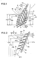
- a radial tyre 1 for heavy duty vehicles has a radial carcass 4 extending between the bead portions of the tyre.
- the carcass 4 has at least one ply, in this embodiment one ply, of cords 4a which are arranged radially of the tyre and embedded in rubber 4b.
- the carcass ply is turned up at the edges thereof around bead cores 3 from the axially inside to the outside thereof.
- a high strength cord such as a steel cord or the like, is used.
- the tyre 1 is provided in each bead portion with a bead reinforcing layer 5.
- the bead reinforcing layer 5 is disposed around the bead core 3, and extends radially outwardly from the bead base portion under the bead core to form an axially inner portion 5A and an axially outer portion 5B.
- the height H5a of the upper edge 5a of the axially inner portion 5A from the bead base line L is larger than the height H5b of the upper edge of the axially outer portion 5B from the bead line L.
- the height H4c of the upper edge 4c of the carcass turnup portion 4B from the bead base line L is larger than the above mentioned height H5b.
- cords of the bead reinforcing layer high tensile cords such as steel cords, glass fibre cords, carbon fibre cords, aromatic polyamide fibre cords and so on can be used, but steel cords are preferable.
- the cords are laid at 20 to 70 degrees to the carcass cords.
- an organic cord layer 9 composed of plural plies of organic fibre cords is disposed axially outwardly of the outer portion 5B of the bead reinforcing layer 5 and the carcass turnup portion 4B. Still furthermore, a bead apex 10 is disposed radially outwardly of the bead core 3.
- the tyre 1 is provided with an inner liner 6 extending from one bead portion to the other bead portion along the inner face of the inner portion 5A of the bead reinforcing layer 5 and the inner face of the carcass main portion 4A through the tyre sidewall portions and tread portion in order to prevent air leakage and penetration of moisture into the carcass and to increase the durability of the carcass and the bead.
- the inner liner 6 is made of a rubber compound having a high airtightness and the compound has a JIS A hardness between 45 and 60 more preferably 50 and 55, and a modulus of elasticity at 200% elongation between 20 and 30 kgf/sq.cm.
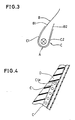
- the inner liner is provided between its upper portion 7A and lower portion 7B with a portion 7C the thickness of which gradually decreases in the direction radially outwardly of the tyre.
- the upper portion 7A and the lower portion 7B are smoothly connected to the upper end 7a and the lower end 7b of the above mentioned middle thickness varying portion 7C, respectively, without any step or sudden change in thickness to avoid stress concentration.
- the lower portion 7B extends radially outwardly from the bead base region beyond the upper edge 5a of the axially inner portion 5A of the bead reinforcing layer 5 to form a thick portion around the upper edge 5a, which thick portion acts to prevent rubber separation in the upper edge region 5a.
- the height H7b of the lower end 7b of the middle portion 7C from the bead base line L is set to be more than 1.2 times the height H5a of the upper edge 5a of the axially inner portion 5A of the bead reinforcing layer 5 from the bead base line L. Furthermore, the height H7a of the upper end 7a of the middle portion 7C from the bead base line L is set to be more than 1.4 times the above mentioned height H5a.
- the thickness of the inner liner 6 is arranged so that the thickness from the inner face of the inner liner 6 to the adjacent reinforcement cords including the carcass cords and the bead reinforcing layer cords satisfies the following conditions:-
- the difference Wd between the thickness W7a from the inner face at the upper end 7a to the carcass cords 4a and the thickness from the inner face at the lower end 7b to the carcass cords 4a is s et to be more than 0.5 times and less than 1.9 times the above mentioned thickness W7a at the upper end 7a so as to make the difference a proper small thickness in order to prevent stress concentration.
- the thickness W7c from the inner face of the inner liner 6 at a point 7c to the cords of the reinforcing layer 5 is more than 0.9 times and less than 1.2 times the above mentioned thickness W7a at the upper end 7a, wherein the point 7c is the point at which height H7c is 0.9 times the height H5a of the upper edge 5a of the inner portion 5A and the thickness of the portion inwards of the inner portion 5A is nearly the same as the thickness of the portion inwards of the carcass main portion 4A.
- the difference Wd is made less than 0.5 times the thickness W7a then the difference is too small, and it becomes impossible to keep a proper thickness for the upper portion 7A when the thickness of the lower portion 7B is set in a proper range. That is, the thickness of the upper portion 7A becomes too thick, and thus the tyre weight and cost are undesirably increased.
- the difference Wd is more than 1.0 times then the difference is so large that generation of stress can not be prevented, and further the upper part 7A becomes too thin when the lower part 7B is set at a proper thickness.
- the thickness W5a from the inner face of the inner liner 6 at the upper edge 5a of the inner portion 5A to the cords of the reinforcing layer 5 is between 2.0mm and 4.5mm.
- W5a is less than 2.0mm, the airtightness and reinforcement become poor, and if it is more than 4.5mm, the rubber thickness becomes so large that the tyre has less flexibility and tyre cost and weight become increased.
- an easy method to make the tyre according to the present invention is to change the shape of the bladder which is used in the tyre vulcanising process.
- test tyres The bead durability of test tyres was evaluated through a running test using a drum tester under the following test conditions:- Tyre sizes : 12R22.5 Rim size : 8.25 x 22.5 Inner pressure : 8 kgf/sq.cm Load : 9,000 km/h Speed : 25 km/h
- Table 1 The test results are indicated in Table 1 using an index based on the assumption that the measured value for the Embodiment tyre 1 is 100. The higher the index then the better the durability.
- the rubber separation at the upper edge of the carcass turned up portion is prevented by forming the axially inner portion on the reinforcing layer, and the rubber separation at the upper edge of this axially inner portion of the bead reinforcing layer is effectively prevented by forming the thickness varying portion on the liner at the position radially outward of the upper edge of the axially inner portion of the reinforcing layer.
Landscapes
- Engineering & Computer Science (AREA)
- Mechanical Engineering (AREA)
- Tires In General (AREA)
Applications Claiming Priority (2)
| Application Number | Priority Date | Filing Date | Title |
|---|---|---|---|
| JP63122650A JP2664062B2 (ja) | 1988-05-18 | 1988-05-18 | 重車両用ラジアルタイヤ |
| JP122650/88 | 1988-05-18 |
Publications (3)
| Publication Number | Publication Date |
|---|---|
| EP0342867A2 true EP0342867A2 (fr) | 1989-11-23 |
| EP0342867A3 EP0342867A3 (en) | 1990-05-16 |
| EP0342867B1 EP0342867B1 (fr) | 1991-12-18 |
Family
ID=14841224
Family Applications (1)
| Application Number | Title | Priority Date | Filing Date |
|---|---|---|---|
| EP89304802A Expired - Lifetime EP0342867B1 (fr) | 1988-05-18 | 1989-05-11 | Pneumatique radial pour poids lourds |
Country Status (4)
| Country | Link |
|---|---|
| US (1) | US5029627A (fr) |
| EP (1) | EP0342867B1 (fr) |
| JP (1) | JP2664062B2 (fr) |
| DE (1) | DE68900567D1 (fr) |
Cited By (3)
| Publication number | Priority date | Publication date | Assignee | Title |
|---|---|---|---|---|
| WO2010070381A1 (fr) * | 2008-12-15 | 2010-06-24 | Pirelli Tyre S.P.A. | Processus de fabrication d'un pneumatique, et pneumatique obtenu à partir de ce dernier |
| EP2708379A4 (fr) * | 2011-05-13 | 2015-10-28 | Sumitomo Rubber Ind | Pneumatique |
| CN107709052A (zh) * | 2015-07-10 | 2018-02-16 | 米其林集团总公司 | 包含低硫弹性体混合物的轮胎 |
Families Citing this family (10)
| Publication number | Priority date | Publication date | Assignee | Title |
|---|---|---|---|---|
| JPH0431109A (ja) * | 1990-05-25 | 1992-02-03 | Sumitomo Rubber Ind Ltd | 重車両用ラジアルタイヤ |
| US5323829A (en) * | 1992-12-28 | 1994-06-28 | The Goodyear Tire & Rubber Company | Tire with carbon fiber reinforcement |
| US6802351B1 (en) * | 1999-07-02 | 2004-10-12 | Bridgestone Corporation | Pneumatic tires |
| US6705371B2 (en) * | 2000-09-13 | 2004-03-16 | Bridgestone Corporation | Pneumatic radial tire |
| US6980903B2 (en) * | 2002-11-01 | 2005-12-27 | Visteon Global Technologies, Inc. | Exhaust gas control using a spark plug ionization signal |
| US6896021B1 (en) * | 2003-03-31 | 2005-05-24 | The Goodyear Tire & Rubber Company | Tire bead geometry |
| WO2005009763A1 (fr) * | 2003-07-28 | 2005-02-03 | The Yokohama Rubber Co.,Ltd. | Pneumatique |
| CN101077684B (zh) * | 2007-06-29 | 2010-04-14 | 青岛双星轮胎工业有限公司 | 全钢丝载重子午线轮胎的新型子口结构 |
| US8091528B2 (en) * | 2010-12-06 | 2012-01-10 | Mcalister Technologies, Llc | Integrated fuel injector igniters having force generating assemblies for injecting and igniting fuel and associated methods of use and manufacture |
| CN110843426B (zh) * | 2019-11-29 | 2021-12-31 | 安徽佳通乘用子午线轮胎有限公司 | 一种高负荷全钢子午线轮胎 |
Family Cites Families (11)
| Publication number | Priority date | Publication date | Assignee | Title |
|---|---|---|---|---|
| GB737760A (en) * | 1953-06-15 | 1955-09-28 | Firestone Tire & Rubber Co | Improvements in or relating to chafer strips for tubeless tire |
| GB1190766A (en) * | 1966-08-10 | 1970-05-06 | Dunlop Company Ltd Formerly Du | Improvements in and relating to Pneumatic Tyres |
| AT327712B (de) * | 1971-11-10 | 1976-02-10 | Semperit Ag | Verfahren zur herstellung eines fahrzeugluftreifens und mit dem verfahren hergestellter fahrzeugluftreifen |
| JPS54162306A (en) * | 1978-06-13 | 1979-12-22 | Sumitomo Rubber Ind | Pneumatic tire provided with carcass with bias structure of textile cord |
| GB2026958B (en) * | 1978-07-29 | 1983-02-09 | Dunlop Ltd | Tyre and wheel rim assemblies |
| JPS59102604A (ja) * | 1982-12-01 | 1984-06-13 | Sumitomo Rubber Ind Ltd | ラジアルタイヤ |
| JP2507288B2 (ja) * | 1982-12-28 | 1996-06-12 | 株式会社ブリヂストン | 重荷重用チュ−ブレス空気入りラジアルタイヤ |
| JPH0635241B2 (ja) * | 1983-05-26 | 1994-05-11 | 株式会社ブリヂストン | 空気入りタイヤ |
| JPS62199329U (fr) * | 1986-06-09 | 1987-12-18 | ||
| JPS6382802A (ja) * | 1986-09-26 | 1988-04-13 | Ohtsu Tire & Rubber Co Ltd | 空気入りタイヤ |
| US4790364A (en) * | 1987-07-27 | 1988-12-13 | The Goodyear Tire & Rubber Company | Sidewall and bead reinforcing structure for a pneumatic aircraft tire |
-
1988
- 1988-05-18 JP JP63122650A patent/JP2664062B2/ja not_active Expired - Fee Related
-
1989
- 1989-05-11 EP EP89304802A patent/EP0342867B1/fr not_active Expired - Lifetime
- 1989-05-11 US US07/350,161 patent/US5029627A/en not_active Expired - Fee Related
- 1989-05-11 DE DE8989304802T patent/DE68900567D1/de not_active Expired - Fee Related
Cited By (6)
| Publication number | Priority date | Publication date | Assignee | Title |
|---|---|---|---|---|
| WO2010070381A1 (fr) * | 2008-12-15 | 2010-06-24 | Pirelli Tyre S.P.A. | Processus de fabrication d'un pneumatique, et pneumatique obtenu à partir de ce dernier |
| US8778111B2 (en) | 2008-12-15 | 2014-07-15 | Pirelli Tyre S.P.A. | Process for manufacturing a tyre, and tyre obtained therefrom |
| EP2708379A4 (fr) * | 2011-05-13 | 2015-10-28 | Sumitomo Rubber Ind | Pneumatique |
| CN105539012A (zh) * | 2011-05-13 | 2016-05-04 | 住友橡胶工业株式会社 | 充气轮胎 |
| CN107709052A (zh) * | 2015-07-10 | 2018-02-16 | 米其林集团总公司 | 包含低硫弹性体混合物的轮胎 |
| CN107709052B (zh) * | 2015-07-10 | 2019-09-03 | 米其林集团总公司 | 包含低硫弹性体混合物的轮胎 |
Also Published As
| Publication number | Publication date |
|---|---|
| JP2664062B2 (ja) | 1997-10-15 |
| JPH01293207A (ja) | 1989-11-27 |
| US5029627A (en) | 1991-07-09 |
| EP0342867A3 (en) | 1990-05-16 |
| DE68900567D1 (de) | 1992-01-30 |
| EP0342867B1 (fr) | 1991-12-18 |
Similar Documents
| Publication | Publication Date | Title |
|---|---|---|
| EP0638445B1 (fr) | Pneumatique à carcasse radiale | |
| EP0371755B1 (fr) | Pneumatique de sécurité | |
| US6273162B1 (en) | Pneumatic tire with specified bead portion | |
| EP0810106A2 (fr) | Bandage pneumatique radial pour poids-lourds | |
| EP0705717A2 (fr) | Bandage pneumatique sans chambre à air | |
| EP0318128A2 (fr) | Bandage pneumatique radial pour poids-lourds | |
| EP0554108B1 (fr) | Bandages pneumatiques radiaux | |
| EP0395039A2 (fr) | Bandage pneumatique radial | |
| EP0342867A2 (fr) | Pneumatique radial pour poids lourds | |
| EP0659596A2 (fr) | Bandage pneumatique pour avions | |
| US4691752A (en) | Pneumatic radial tire | |
| EP0744305A2 (fr) | Bandage pneumatique | |
| EP1405736B1 (fr) | Pneumatique | |
| US6736178B2 (en) | Pneumatic tire with specified bead portion | |
| EP1207055B1 (fr) | Bandage pneumatique | |
| EP0732228A2 (fr) | Bandage pneumatique | |
| EP0778164A1 (fr) | Pneumatique a carcasse radiale | |
| US4140166A (en) | Pneumatic radial tire | |
| EP0810105B1 (fr) | Bandages pneumatiques radiaux avec une couche renforçant les flancs | |
| US4705091A (en) | Heavy duty pneumatic radial tires | |
| EP1844956A2 (fr) | Pneumatique avec couche de renfort des flancs | |
| EP0409518A2 (fr) | Pneumatiques pour motocyclette | |
| EP0698513A2 (fr) | Bandage pneumatique radial | |
| US5151139A (en) | Heavy duty radial tire having durable buttress portion | |
| EP1640186A1 (fr) | Pneumatique gonflable |
Legal Events
| Date | Code | Title | Description |
|---|---|---|---|
| PUAI | Public reference made under article 153(3) epc to a published international application that has entered the european phase |
Free format text: ORIGINAL CODE: 0009012 |
|
| AK | Designated contracting states |
Kind code of ref document: A2 Designated state(s): DE FR GB |
|
| PUAL | Search report despatched |
Free format text: ORIGINAL CODE: 0009013 |
|
| AK | Designated contracting states |
Kind code of ref document: A3 Designated state(s): DE FR GB |
|
| 17P | Request for examination filed |
Effective date: 19901022 |
|
| 17Q | First examination report despatched |
Effective date: 19910429 |
|
| GRAA | (expected) grant |
Free format text: ORIGINAL CODE: 0009210 |
|
| AK | Designated contracting states |
Kind code of ref document: B1 Designated state(s): DE FR GB |
|
| REF | Corresponds to: |
Ref document number: 68900567 Country of ref document: DE Date of ref document: 19920130 |
|
| ET | Fr: translation filed | ||
| PLBE | No opposition filed within time limit |
Free format text: ORIGINAL CODE: 0009261 |
|
| STAA | Information on the status of an ep patent application or granted ep patent |
Free format text: STATUS: NO OPPOSITION FILED WITHIN TIME LIMIT |
|
| 26N | No opposition filed | ||
| PGFP | Annual fee paid to national office [announced via postgrant information from national office to epo] |
Ref country code: DE Payment date: 20010508 Year of fee payment: 13 |
|
| PGFP | Annual fee paid to national office [announced via postgrant information from national office to epo] |
Ref country code: GB Payment date: 20010509 Year of fee payment: 13 |
|
| PGFP | Annual fee paid to national office [announced via postgrant information from national office to epo] |
Ref country code: FR Payment date: 20010518 Year of fee payment: 13 |
|
| REG | Reference to a national code |
Ref country code: GB Ref legal event code: IF02 |
|
| PG25 | Lapsed in a contracting state [announced via postgrant information from national office to epo] |
Ref country code: GB Free format text: LAPSE BECAUSE OF NON-PAYMENT OF DUE FEES Effective date: 20020511 |
|
| PG25 | Lapsed in a contracting state [announced via postgrant information from national office to epo] |
Ref country code: DE Free format text: LAPSE BECAUSE OF NON-PAYMENT OF DUE FEES Effective date: 20021203 |
|
| GBPC | Gb: european patent ceased through non-payment of renewal fee |
Effective date: 20020511 |
|
| PG25 | Lapsed in a contracting state [announced via postgrant information from national office to epo] |
Ref country code: FR Free format text: LAPSE BECAUSE OF NON-PAYMENT OF DUE FEES Effective date: 20030131 |
|
| REG | Reference to a national code |
Ref country code: FR Ref legal event code: ST |