EP0342865A1 - Kupplungsscheibe mit stossgedämpften Reibbelägen - Google Patents
Kupplungsscheibe mit stossgedämpften Reibbelägen Download PDFInfo
- Publication number
- EP0342865A1 EP0342865A1 EP89304799A EP89304799A EP0342865A1 EP 0342865 A1 EP0342865 A1 EP 0342865A1 EP 89304799 A EP89304799 A EP 89304799A EP 89304799 A EP89304799 A EP 89304799A EP 0342865 A1 EP0342865 A1 EP 0342865A1
- Authority
- EP
- European Patent Office
- Prior art keywords
- assembly
- friction
- laminate
- clutch disk
- backing plate
- Prior art date
- Legal status (The legal status is an assumption and is not a legal conclusion. Google has not performed a legal analysis and makes no representation as to the accuracy of the status listed.)
- Withdrawn
Links
- 230000000712 assembly Effects 0.000 description 3
- 238000000429 assembly Methods 0.000 description 3
- 238000010168 coupling process Methods 0.000 description 2
- 230000001154 acute effect Effects 0.000 description 1
- 230000006835 compression Effects 0.000 description 1
- 238000007906 compression Methods 0.000 description 1
- 238000005336 cracking Methods 0.000 description 1
- 230000000694 effects Effects 0.000 description 1
- 230000014759 maintenance of location Effects 0.000 description 1
- 238000004519 manufacturing process Methods 0.000 description 1
- 230000007704 transition Effects 0.000 description 1
- 238000003466 welding Methods 0.000 description 1
Images

Classifications
-
- F—MECHANICAL ENGINEERING; LIGHTING; HEATING; WEAPONS; BLASTING
- F16—ENGINEERING ELEMENTS AND UNITS; GENERAL MEASURES FOR PRODUCING AND MAINTAINING EFFECTIVE FUNCTIONING OF MACHINES OR INSTALLATIONS; THERMAL INSULATION IN GENERAL
- F16D—COUPLINGS FOR TRANSMITTING ROTATION; CLUTCHES; BRAKES
- F16D11/00—Clutches in which the members have interengaging parts
- F16D11/02—Clutches in which the members have interengaging parts disengaged by a contact of a part mounted on the clutch with a stationarily-mounted member
-
- F—MECHANICAL ENGINEERING; LIGHTING; HEATING; WEAPONS; BLASTING
- F16—ENGINEERING ELEMENTS AND UNITS; GENERAL MEASURES FOR PRODUCING AND MAINTAINING EFFECTIVE FUNCTIONING OF MACHINES OR INSTALLATIONS; THERMAL INSULATION IN GENERAL
- F16D—COUPLINGS FOR TRANSMITTING ROTATION; CLUTCHES; BRAKES
- F16D13/00—Friction clutches
- F16D13/58—Details
- F16D13/60—Clutching elements
- F16D13/64—Clutch-plates; Clutch-lamellae
-
- B—PERFORMING OPERATIONS; TRANSPORTING
- B05—SPRAYING OR ATOMISING IN GENERAL; APPLYING FLUENT MATERIALS TO SURFACES, IN GENERAL
- B05D—PROCESSES FOR APPLYING FLUENT MATERIALS TO SURFACES, IN GENERAL
- B05D5/00—Processes for applying liquids or other fluent materials to surfaces to obtain special surface effects, finishes or structures
- B05D5/08—Processes for applying liquids or other fluent materials to surfaces to obtain special surface effects, finishes or structures to obtain an anti-friction or anti-adhesive surface
-
- F—MECHANICAL ENGINEERING; LIGHTING; HEATING; WEAPONS; BLASTING
- F16—ENGINEERING ELEMENTS AND UNITS; GENERAL MEASURES FOR PRODUCING AND MAINTAINING EFFECTIVE FUNCTIONING OF MACHINES OR INSTALLATIONS; THERMAL INSULATION IN GENERAL
- F16D—COUPLINGS FOR TRANSMITTING ROTATION; CLUTCHES; BRAKES
- F16D13/00—Friction clutches
- F16D13/58—Details
- F16D13/60—Clutching elements
- F16D13/64—Clutch-plates; Clutch-lamellae
- F16D2013/642—Clutch-plates; Clutch-lamellae with resilient attachment of frictions rings or linings to their supporting discs or plates for allowing limited axial displacement of these rings or linings
Definitions
- This invention relates to clutch disks adapted for use in dry friction clutches. More particularly, the invention relates to means for securing friction elements to such disks.
- transitional clutch engagement In certain heavy duty clutch designs, there is a need to accommodate lateral deflection of friction elements which occurs during transition between clutch disengagement and full clutch engagement, referred to herein as "transitional" clutch engagement. In heavy duty clutch systems, the greatest amount of lateral deflection occurs during the transitional engagement phase.
- lateral deflection is typically accommodated by cushioning the spacing between friction elements positioned on opposed or opposite sides of the clutch disk. This is accomplished by adding spaces, springs, or both between opposed friction elements.
- Such systems do not address the problem of stress in the rigid connections between the friction elements and disks.
- Most systems will employ spot welding for the connection, or will utilize rivets for this purpose. The stress loads on the spot welds or rivets are relatively high, causing frequent cracking within the otherwise normal useful life of the clutch.
- rigid connectors are avoided at locations of high stress, such as at the interface between friction element assemblies and the clutch disks to which such assemblies are secured.
- the driven clutch disk with friction element assembly disclosed herein contains a friction element-to-disk connection which does not include rivets or welds.
- the disk includes a plurality of circumferentially and uniformly spaced openings, wherein one set of friction elements is supported over each opening.
- Each friction element assembly defines a pair of identical laminates opposingly joined together over one opening, each laminate positioned on an opposite face of the disk.
- Each laminate comprises a backing plate having one friction member rigidly secured thereto, each backing plate of each pair of laminates defining a central cushion region in an area radially coterminous with and positioned between the friction members.
- Each backing plate also includes a pair of laminate joinder sections at opposite radially extending ends of the cushion region, each section contiguous with one radial boundary of the cushion region.
- Each friction element assembly defines at each end thereof a pair of integral sliding wedge supports which clasp the disk at the radial boundaries of each opening for supporting each friction assembly without the use of rigid, fixed connectors.
- the sliding wedge supports provide the sole means of retention of each assembly over one disk opening, and the supports are adapted to accommodate significant lateral deflection of the laminates during transitional clutch engagement.
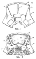
- a clutch disk 10 of the type adapted for engagement and release in a dry friction clutch system (not shown) is represented fragmentarily.
- the disk 10 includes a plurality of pairs of apertures or openings 12 (only one pair of which is shown) for support of a like plurality of friction element assemblies 20 ( Figure 2).
- Each pair of apertures 12 includes a dividing center rib 16 for purposes explained hereinbelow.
- the disk 10 includes a plurality of annularly arranged damper spring apertures 18 for support of damper springs 22 ( Figure 2).
- a fully assembled clutch disk 10 again shown fragmentarily, includes a plurality of radially extending arms 24 (only one of which is shown), each of which supports a friction element assembly 20 over the pair of apertures 12 shown in Figure 1.
- Each pair of apertures 12 defines a pair of circumferentially spaced radially extending boundaries 14.
- Each boundary 14 in a preferred form is equidistant from the radially extending center rib 16.
- Each friction element assembly 20 ( Figure 2) is made up of a pair of friction laminates 30 as shown in particular detail in Figures 3 and 4. Each laminate includes a friction member 32 bonded to a backing plate 34. Referring momentarily to Figure 5, the pair of backing plates 34 of each friction element assembly 20 are joined together at laminate joinder sections 36. The joinder sections 36 are coupled together by either spot welds as shown at 46 of Figure 5 or by rivet connection as shown at 48 of Figure 5. (Both coupling methods are shown in the same Figure for convenience only. Typically, only one coupling method would be utilized.)
- Each laminate includes an integral sliding wedge support 38, which extends outwardly of each joinder section 36.
- Each joinder section 36 ( Figure 4) is laterally off-set from both the portion of the backing plate 34 underlying the friction member 32 as well as from the sliding wedge support 38.
- Elbows 42 and 44 join the respective sections together as shown.
- Each sliding wedge support 38 makes a contact with the disk 10 at a contact interface 40.
- the contact established between the interface 40 and the disk will define a line, not a point, and that the sole means of support for the friction element assembly 20 will be provided by the clasping action of two pairs of sliding wedge supports 38 at opposite ends of the assembly 20 ( Figure 5).
- the contact interface 40 will be under a slight compression load for alleviating any risk of non-contact resulting from manufacturing tolerances.
- a central cushion region 50 is positioned between the portions of the assembled backing plates 34 underneath the friction members 32.
- This region defines a space which provides a "cushioned effect" adapted to absorb lateral deflections associated with transitional clutch engagements.
- the rib 16 will act to limit deflection of the individual backing plate portions 34 which underlie the friction members 32 during transitional clutch engagement. It is envisioned, however, that the present invention is not limited to the inclusion of such a rib 16.
- the sliding wedge supports 38 will extend at a slight acute angle with respect to the axis "a-a" of the disk 10. This angle will preferably lie within a range of 1 to 5 degrees to ensure a line rather than surface contact, regardless of the amount of lateral deflection of the disk 10.
Landscapes
- Engineering & Computer Science (AREA)
- General Engineering & Computer Science (AREA)
- Mechanical Engineering (AREA)
- Mechanical Operated Clutches (AREA)
Applications Claiming Priority (2)
| Application Number | Priority Date | Filing Date | Title |
|---|---|---|---|
| US193853 | 1988-05-13 | ||
| US07/193,853 US4858742A (en) | 1988-05-13 | 1988-05-13 | Clutch disk with cushioned friction element assembly |
Publications (1)
| Publication Number | Publication Date |
|---|---|
| EP0342865A1 true EP0342865A1 (de) | 1989-11-23 |
Family
ID=22715281
Family Applications (1)
| Application Number | Title | Priority Date | Filing Date |
|---|---|---|---|
| EP89304799A Withdrawn EP0342865A1 (de) | 1988-05-13 | 1989-05-11 | Kupplungsscheibe mit stossgedämpften Reibbelägen |
Country Status (7)
| Country | Link |
|---|---|
| US (1) | US4858742A (de) |
| EP (1) | EP0342865A1 (de) |
| JP (1) | JPH0211927A (de) |
| KR (1) | KR900018561A (de) |
| AU (1) | AU612950B2 (de) |
| BR (1) | BR8901985A (de) |
| ZA (1) | ZA893038B (de) |
Cited By (6)
| Publication number | Priority date | Publication date | Assignee | Title |
|---|---|---|---|---|
| EP0529067A4 (de) * | 1991-03-12 | 1994-03-09 | Russell D. Ide | |
| GB2306619A (en) * | 1995-10-20 | 1997-05-07 | Exedy Corp | Damper disc assembly and friction coupling device for clutch |
| GB2318620A (en) * | 1995-10-20 | 1998-04-29 | Exedy Corp | Friction coupling device |
| EP1936230A1 (de) | 2006-12-20 | 2008-06-25 | ZF Friedrichshafen AG | Verfahren zur Befestigung eines Reibbelags an einer Kupplungsscheibe und Kupplungsscheibe |
| DE102008040962A1 (de) | 2007-09-13 | 2009-03-19 | Zf Friedrichshafen Ag | Verfahren zum Herstellen einer Verbindung zwischen einer Kupplungsscheibe und einem Reibbelag und Kupplungsscheibe |
| DE10038410B4 (de) * | 2000-08-07 | 2010-06-24 | Zf Sachs Ag | Kupplungsscheibe |
Families Citing this family (7)
| Publication number | Priority date | Publication date | Assignee | Title |
|---|---|---|---|---|
| FR2663701B1 (fr) * | 1990-06-22 | 1992-11-27 | Valeo | Disque de friction, notamment pour embrayage. |
| FR2666859B1 (fr) * | 1990-09-19 | 1992-11-27 | Valeo | Disque de friction, notamment pour embrayage. |
| JPH1172124A (ja) * | 1997-08-29 | 1999-03-16 | Exedy Corp | クラッチディスク及びクラッチディスク組立体 |
| US6015035A (en) * | 1997-12-03 | 2000-01-18 | Exedy Corporation | Clutch disk |
| US7021448B2 (en) * | 2002-12-10 | 2006-04-04 | Zf Sachs Ag | Clutch disk for a friction clutch |
| AT514738A1 (de) * | 2013-08-23 | 2015-03-15 | Miba Frictec Gmbh | Reibelement |
| DE102014212949A1 (de) * | 2014-07-03 | 2016-01-07 | Schaeffler Technologies AG & Co. KG | Kupplungsscheibe |
Citations (5)
| Publication number | Priority date | Publication date | Assignee | Title |
|---|---|---|---|---|
| FR1017688A (fr) * | 1950-05-12 | 1952-12-17 | Schrynemaekers & Cie | Perfectionnements aux dispositifs d'embrayage |
| US3209876A (en) * | 1962-04-06 | 1965-10-05 | Jurid Werke Gmbh | Friction producing device |
| US3526307A (en) * | 1968-07-29 | 1970-09-01 | Borg Warner | Friction member |
| GB2045878A (en) * | 1979-04-02 | 1980-11-05 | Goodyear Aerospace Corp | Method and means for fastening friction pads |
| GB2141190A (en) * | 1980-11-17 | 1984-12-12 | Borg Warner | Clutch driven plate assembly with axial resilience |
Family Cites Families (14)
| Publication number | Priority date | Publication date | Assignee | Title |
|---|---|---|---|---|
| US1754233A (en) * | 1927-03-09 | 1930-04-15 | Russell Mfg Co | Friction element |
| US1868543A (en) * | 1930-04-03 | 1932-07-26 | Monmouth Products Company | Clutch plate |
| US1956828A (en) * | 1931-03-02 | 1934-05-01 | Continental Motors Corp | Clutch disk |
| US1913802A (en) * | 1931-11-10 | 1933-06-13 | Peter A Gregory | Clutch disk |
| US2015890A (en) * | 1934-01-27 | 1935-10-01 | Gottschalk Hubert | Clutch disk |
| US2053622A (en) * | 1935-07-25 | 1936-09-08 | Gen Motors Corp | Clutch driven plate |
| US3064782A (en) * | 1958-12-15 | 1962-11-20 | Bendix Corp | Lining button-spring loaded |
| US3164236A (en) * | 1961-06-22 | 1965-01-05 | Bendix Corp | Clutch plates and the like |
| FR1502088A (fr) * | 1966-10-06 | 1967-11-18 | Hispano Suiza Lallemant Soc | Perfectionnements apportés aux dispositifs à disques de friction, notamment aux freins à disques |
| GB1407966A (en) * | 1971-11-04 | 1975-10-01 | Dunlop Ltd | Friction members |
| FR2424446A1 (fr) * | 1978-04-26 | 1979-11-23 | Ferodo Sa | Disque de friction a elasticite axiale |
| US4377225A (en) * | 1980-11-17 | 1983-03-22 | Borg-Warner Corporation | Clutch driven plate assembly with variable friction area |
| US4548302A (en) * | 1983-11-30 | 1985-10-22 | Borg-Warner Corporation | Two-stage clutch damper assembly |
| US4556136A (en) * | 1983-11-30 | 1985-12-03 | Borg-Warner Corporation | Clutch driven plate assembly |
-
1988
- 1988-05-13 US US07/193,853 patent/US4858742A/en not_active Expired - Fee Related
-
1989
- 1989-04-19 AU AU33186/89A patent/AU612950B2/en not_active Expired - Fee Related
- 1989-04-25 ZA ZA893038A patent/ZA893038B/xx unknown
- 1989-04-27 BR BR898901985A patent/BR8901985A/pt unknown
- 1989-05-11 JP JP1116250A patent/JPH0211927A/ja active Pending
- 1989-05-11 EP EP89304799A patent/EP0342865A1/de not_active Withdrawn
- 1989-05-11 KR KR1019890006347A patent/KR900018561A/ko not_active Withdrawn
Patent Citations (5)
| Publication number | Priority date | Publication date | Assignee | Title |
|---|---|---|---|---|
| FR1017688A (fr) * | 1950-05-12 | 1952-12-17 | Schrynemaekers & Cie | Perfectionnements aux dispositifs d'embrayage |
| US3209876A (en) * | 1962-04-06 | 1965-10-05 | Jurid Werke Gmbh | Friction producing device |
| US3526307A (en) * | 1968-07-29 | 1970-09-01 | Borg Warner | Friction member |
| GB2045878A (en) * | 1979-04-02 | 1980-11-05 | Goodyear Aerospace Corp | Method and means for fastening friction pads |
| GB2141190A (en) * | 1980-11-17 | 1984-12-12 | Borg Warner | Clutch driven plate assembly with axial resilience |
Cited By (10)
| Publication number | Priority date | Publication date | Assignee | Title |
|---|---|---|---|---|
| EP0529067A4 (de) * | 1991-03-12 | 1994-03-09 | Russell D. Ide | |
| GB2306619A (en) * | 1995-10-20 | 1997-05-07 | Exedy Corp | Damper disc assembly and friction coupling device for clutch |
| GB2318620A (en) * | 1995-10-20 | 1998-04-29 | Exedy Corp | Friction coupling device |
| US5816925A (en) * | 1995-10-20 | 1998-10-06 | Exedy Corporation | Damper disk assembly, frictional coupling portion and clutch disk assembly |
| GB2318620B (en) * | 1995-10-20 | 1999-04-14 | Exedy Corp | Friction coupling device |
| GB2306619B (en) * | 1995-10-20 | 1999-04-14 | Exedy Corp | Damper disk assembly for a clutch |
| DE10038410B4 (de) * | 2000-08-07 | 2010-06-24 | Zf Sachs Ag | Kupplungsscheibe |
| EP1936230A1 (de) | 2006-12-20 | 2008-06-25 | ZF Friedrichshafen AG | Verfahren zur Befestigung eines Reibbelags an einer Kupplungsscheibe und Kupplungsscheibe |
| DE102008040962A1 (de) | 2007-09-13 | 2009-03-19 | Zf Friedrichshafen Ag | Verfahren zum Herstellen einer Verbindung zwischen einer Kupplungsscheibe und einem Reibbelag und Kupplungsscheibe |
| EP2039951A2 (de) | 2007-09-13 | 2009-03-25 | ZF Friedrichshafen AG | Verfahren zum Herstellen einer Verbindung zwischen einer Kupplungsscheibe und einem Reibbelag und Kupplungsscheibe |
Also Published As
| Publication number | Publication date |
|---|---|
| JPH0211927A (ja) | 1990-01-17 |
| ZA893038B (en) | 1989-12-27 |
| AU612950B2 (en) | 1991-07-18 |
| BR8901985A (pt) | 1989-12-05 |
| US4858742A (en) | 1989-08-22 |
| KR900018561A (ko) | 1990-12-21 |
| AU3318689A (en) | 1989-11-16 |
Similar Documents
| Publication | Publication Date | Title |
|---|---|---|
| EP0342865A1 (de) | Kupplungsscheibe mit stossgedämpften Reibbelägen | |
| US5452783A (en) | Liner support disc, especially for a motor vehicle clutch | |
| US4516672A (en) | Progressive engagement friction disc | |
| US20050082125A1 (en) | Floating brake rotor assembly with non-load bearing pins | |
| US4967893A (en) | Friction assembly | |
| US4646900A (en) | Friction material and carrier plate assembly | |
| US2448880A (en) | Friction clutch plate | |
| JPS60234140A (ja) | 摩擦デイスク | |
| EP0427489B1 (de) | Räder mit eingebauten Bremsscheiben | |
| EP1382873A2 (de) | Kupplungsscheibe | |
| EP0115280A1 (de) | Bremsapparatur | |
| US6702082B2 (en) | Leaf spring arrangement, especially for attaching the pressure plate of a pressure plate assembly to a housing | |
| US4860872A (en) | Friction disc assembly | |
| US4869356A (en) | Clutch disk with spring cushioned friction element | |
| RU2360159C2 (ru) | Дисковый тормоз и стабилизирующий диск элемент | |
| US2646151A (en) | Clutch plate | |
| CN107339334A (zh) | 用于机动车的离合器盘 | |
| US4846329A (en) | Friction element for clutch | |
| US5601173A (en) | Liner support disc for supporting friction liners, especially for a motor vehicle | |
| US8418829B2 (en) | Cushioned ceramic driven disc assembly with ceramic friction pads fixed to slotted backer plates | |
| US4781280A (en) | Friction clutch | |
| US4529078A (en) | Clutch disc | |
| GB2313165A (en) | Clutch disc assembly | |
| CN215293331U (zh) | 整体式离合器从动盘波形片 | |
| US6564920B2 (en) | Driver disk for a clutch plate |
Legal Events
| Date | Code | Title | Description |
|---|---|---|---|
| PUAI | Public reference made under article 153(3) epc to a published international application that has entered the european phase |
Free format text: ORIGINAL CODE: 0009012 |
|
| AK | Designated contracting states |
Kind code of ref document: A1 Designated state(s): DE ES FR GB IT NL SE |
|
| 17P | Request for examination filed |
Effective date: 19900515 |
|
| STAA | Information on the status of an ep patent application or granted ep patent |
Free format text: STATUS: THE APPLICATION HAS BEEN WITHDRAWN |
|
| 18W | Application withdrawn |
Withdrawal date: 19910415 |
|
| R18W | Application withdrawn (corrected) |
Effective date: 19910415 |