EP0342799B1 - Verfahren zur Lösungsmittelextraktion und Anlage dafür - Google Patents
Verfahren zur Lösungsmittelextraktion und Anlage dafür Download PDFInfo
- Publication number
- EP0342799B1 EP0342799B1 EP19890303966 EP89303966A EP0342799B1 EP 0342799 B1 EP0342799 B1 EP 0342799B1 EP 19890303966 EP19890303966 EP 19890303966 EP 89303966 A EP89303966 A EP 89303966A EP 0342799 B1 EP0342799 B1 EP 0342799B1
- Authority
- EP
- European Patent Office
- Prior art keywords
- extraction section
- liquid
- section
- solute
- back extraction
- Prior art date
- Legal status (The legal status is an assumption and is not a legal conclusion. Google has not performed a legal analysis and makes no representation as to the accuracy of the status listed.)
- Expired - Lifetime
Links
- 238000000638 solvent extraction Methods 0.000 title claims description 27
- 238000000034 method Methods 0.000 title claims description 11
- 238000000605 extraction Methods 0.000 claims description 90
- 239000007788 liquid Substances 0.000 claims description 48
- 238000011144 upstream manufacturing Methods 0.000 claims description 25
- 229910052770 Uranium Inorganic materials 0.000 claims description 16
- JFALSRSLKYAFGM-UHFFFAOYSA-N uranium(0) Chemical compound [U] JFALSRSLKYAFGM-UHFFFAOYSA-N 0.000 claims description 16
- 238000004064 recycling Methods 0.000 claims description 8
- GRYLNZFGIOXLOG-UHFFFAOYSA-N Nitric acid Chemical compound O[N+]([O-])=O GRYLNZFGIOXLOG-UHFFFAOYSA-N 0.000 claims description 7
- 229910017604 nitric acid Inorganic materials 0.000 claims description 7
- 239000003350 kerosene Substances 0.000 claims description 3
- STCOOQWBFONSKY-UHFFFAOYSA-N tributyl phosphate Chemical compound CCCCOP(=O)(OCCCC)OCCCC STCOOQWBFONSKY-UHFFFAOYSA-N 0.000 claims description 3
- 239000002904 solvent Substances 0.000 description 15
- 229910002007 uranyl nitrate Inorganic materials 0.000 description 11
- 238000010586 diagram Methods 0.000 description 6
- 239000008346 aqueous phase Substances 0.000 description 5
- 230000000694 effects Effects 0.000 description 4
- 238000001704 evaporation Methods 0.000 description 4
- 230000008020 evaporation Effects 0.000 description 4
- 238000000746 purification Methods 0.000 description 4
- 239000012141 concentrate Substances 0.000 description 3
- 239000012535 impurity Substances 0.000 description 3
- 239000012074 organic phase Substances 0.000 description 3
- 239000003085 diluting agent Substances 0.000 description 2
- 239000012071 phase Substances 0.000 description 2
- 230000009286 beneficial effect Effects 0.000 description 1
- 238000006243 chemical reaction Methods 0.000 description 1
- 238000004090 dissolution Methods 0.000 description 1
- 229910000078 germane Inorganic materials 0.000 description 1
- 238000004519 manufacturing process Methods 0.000 description 1
- 229910052751 metal Inorganic materials 0.000 description 1
- 239000002184 metal Substances 0.000 description 1
- 239000003960 organic solvent Substances 0.000 description 1
- 238000005192 partition Methods 0.000 description 1
- 238000011084 recovery Methods 0.000 description 1
- 238000005201 scrubbing Methods 0.000 description 1
- 238000004513 sizing Methods 0.000 description 1
- MZFRHHGRNOIMLW-UHFFFAOYSA-J uranium(4+);tetrafluoride Chemical compound F[U](F)(F)F MZFRHHGRNOIMLW-UHFFFAOYSA-J 0.000 description 1
Images

Classifications
-
- C—CHEMISTRY; METALLURGY
- C22—METALLURGY; FERROUS OR NON-FERROUS ALLOYS; TREATMENT OF ALLOYS OR NON-FERROUS METALS
- C22B—PRODUCTION AND REFINING OF METALS; PRETREATMENT OF RAW MATERIALS
- C22B60/00—Obtaining metals of atomic number 87 or higher, i.e. radioactive metals
- C22B60/02—Obtaining thorium, uranium, or other actinides
- C22B60/0204—Obtaining thorium, uranium, or other actinides obtaining uranium
- C22B60/0217—Obtaining thorium, uranium, or other actinides obtaining uranium by wet processes
- C22B60/0221—Obtaining thorium, uranium, or other actinides obtaining uranium by wet processes by leaching
- C22B60/0226—Obtaining thorium, uranium, or other actinides obtaining uranium by wet processes by leaching using acidic solutions or liquors
- C22B60/0239—Obtaining thorium, uranium, or other actinides obtaining uranium by wet processes by leaching using acidic solutions or liquors nitric acid containing ion as active agent
-
- B—PERFORMING OPERATIONS; TRANSPORTING
- B01—PHYSICAL OR CHEMICAL PROCESSES OR APPARATUS IN GENERAL
- B01D—SEPARATION
- B01D11/00—Solvent extraction
- B01D11/04—Solvent extraction of solutions which are liquid
-
- B—PERFORMING OPERATIONS; TRANSPORTING
- B01—PHYSICAL OR CHEMICAL PROCESSES OR APPARATUS IN GENERAL
- B01D—SEPARATION
- B01D11/00—Solvent extraction
- B01D11/04—Solvent extraction of solutions which are liquid
- B01D11/0488—Flow sheets
-
- C—CHEMISTRY; METALLURGY
- C22—METALLURGY; FERROUS OR NON-FERROUS ALLOYS; TREATMENT OF ALLOYS OR NON-FERROUS METALS
- C22B—PRODUCTION AND REFINING OF METALS; PRETREATMENT OF RAW MATERIALS
- C22B60/00—Obtaining metals of atomic number 87 or higher, i.e. radioactive metals
- C22B60/02—Obtaining thorium, uranium, or other actinides
- C22B60/0204—Obtaining thorium, uranium, or other actinides obtaining uranium
- C22B60/0217—Obtaining thorium, uranium, or other actinides obtaining uranium by wet processes
- C22B60/0252—Obtaining thorium, uranium, or other actinides obtaining uranium by wet processes treatment or purification of solutions or of liquors or of slurries
- C22B60/026—Obtaining thorium, uranium, or other actinides obtaining uranium by wet processes treatment or purification of solutions or of liquors or of slurries liquid-liquid extraction with or without dissolution in organic solvents
-
- Y—GENERAL TAGGING OF NEW TECHNOLOGICAL DEVELOPMENTS; GENERAL TAGGING OF CROSS-SECTIONAL TECHNOLOGIES SPANNING OVER SEVERAL SECTIONS OF THE IPC; TECHNICAL SUBJECTS COVERED BY FORMER USPC CROSS-REFERENCE ART COLLECTIONS [XRACs] AND DIGESTS
- Y02—TECHNOLOGIES OR APPLICATIONS FOR MITIGATION OR ADAPTATION AGAINST CLIMATE CHANGE
- Y02P—CLIMATE CHANGE MITIGATION TECHNOLOGIES IN THE PRODUCTION OR PROCESSING OF GOODS
- Y02P10/00—Technologies related to metal processing
- Y02P10/20—Recycling
Definitions
- This invention relates to a method of solvent extraction and apparatus therefor in the form of contactors of the kind having a forward extraction section for the selective extraction of a desired solute from a feed liquid into an extractant liquid, the extractant liquid being arranged to flow from an upstream end of the forward extraction section to a downstream end thereof, an inlet for the introduction of the solute-containing feed liquid into the forward extraction section, an outlet for the removal of the solute-depleted said feed liquid from the forward extraction section, a back extraction section for the extraction of the desired solute from the solute-containing extractant liquid into a backwash liquid, an inlet for the introduction of the backwash liquid into the back extraction section, an outlet for the removal of the solute-containing said backwash liquid from the back extraction section, the solute-containing extractant liquid being arranged to flow from the upstream end of the back extraction section to the downstream end thereof, and a line for recycling backwashed extractant liquid from the downstream end of the back extraction section to the upstream end of the forward extraction section.
- upstream
- a typical application of such a contactor is in the processing of crude uranium ores to produce nuclear grade uranium.
- One stage in such processing involves the dissolution of the impure ores in nitric acid and purification to yield a substantially pure solution of uranyl nitrate which is then concentrated by evaporation for subsequent conversion to uranium tetrafluoride followed by reduction of the tetrafluoride to uranium metal.
- Purification is carried out using solvent extraction to transfer, in a forward extraction section, uranyl nitrate from an aqueous feed liquor of nitric acid containing the dissolved crude uranium ore into an organic extractant (usually tri-n-butyl phosphate in an odourless kerosene diluent).
- the organic extractant is subsequently contacted, in a back extraction section, with an aqueous backwash liquor such as dilute nitric acid to transfer the uranyl nitrate into the backwash liquor.
- the forward extraction section the conditions are adjusted so that the uranium transfers into the extractant leaving the impurities, present in the crude ore, in the feed liquor which is then termed the raffinate.
- Evaporation is an energy-intensive and hence expensive process which means that it could be economically beneficial if it were feasible to achieve greater levels of concentration prior to evaporation, not only for recovery of uranium but for solvent extraction processes generally in circumstances where limits are imposed on the concentration of the desired solute in the backwash liquid.
- the solvent extraction contactor there is a duct connected from a location intermediate the upstream and downstream ends of the back extraction section to the forward extraction section.
- part of the extractant liquid is recycled to the forward extraction section from the back extraction section so that extractant liquid which is still partially loaded with solute is recycled back to the forward extraction section.
- the recycled liquid instead of recycling only extractant liquid which has been fully backwashed, as in conventional solvent extraction contactors, the recycled liquid comprises both fully backwashed and partially backwashed components. As will be described below, this has the effect of modifying the McCabe-Thiele diagram operating line in such a way that greater solute concentration in the backwash liquid can be achieved.
- the recycled partially loaded extractant liquid is reintroduced into the forward extraction section at a location intermediate the upstream and downstream ends of the latter.
- the forward and back extraction sections may comprise various types of solvent extraction equipment; for example each section may comprise a cascade of mixer-settler stages or each may comprise at least one solvent extraction column, such as a pulsed column.
- the recycled partially loaded extractant liquid is derived from one of the cascade stages preceding, ie upstream of, the final stage of the back extraction cascade and is preferably reintroduced into a stage of the forward extraction cascade downstream of the first stage of the latter.
- the recycled partially-loaded extractant liquid may be obtained from a location intermediate the ends of the column (or one of the columns) and may be reintroduced into the forward extraction column (or one of the forward extraction columns) at a location intermediate the ends of the latter.
- the forward extraction section may, if desired, be constituted by one type of contactor and the back extraction section by another. Conceivably each or either extraction system may comprise two or more different types of contactor.
- a conventional solvent extraction plant for the purification of uranium comprises a forward extraction (FX) section 10 and a back extraction (BX) section 12 each comprising a cascade of mixer-settler stages or other contacting equipment.
- a feed liquor comprising crude uranium ore dissolved in nitric acid is supplied at location 14 to the FX section 10 and is contacted with an organic solvent supplied at the upstream end 16 of the FX section so that uranyl nitrate present in the feed liquor phase is extracted into the solvent phase which typically comprises 20% tri-n-butyl phosphate (as extractant) in odourless kerosene (as diluent).
- the impurity-bearing feed liquor, depleted of uranyl nitrate, is removed at 18 as raffinate at the upstream end of the FX section 10 for subsequent treatment and disposal.
- the uranyl nitrate-bearing solvent is introduced (at 20) into the BX section 12 where it is backwashed with an aqueous phase comprising weak nitric acid which is supplied at point 22 at the downstream end of the BX section and is taken off at point 24 at the upstream end of the latter.
- aqueous phase comprising weak nitric acid
- the loaded backwash liquor is subsequently treated by evaporation to concentrate its uranium content.
- the backwashed solvent is taken off at the downstream end of the BX section and is recycled via the line 26 to the upstream end of the FX section for re-use.
- the above description is somewhat simplified and makes no reference to the use of a scrubbing section which in practice may be compounded with the FX section and is used to contact the organic phase passing the feed point 14 with fresh aqueous phase which serves to wash or scrub impurities from the organic phase.
- this is not germane to the present invention and will not therefore be described in detail except to mention that the aqueous scrub is introduced at point 28 at the downstream end of the FX section.
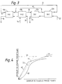
- this shows a typical McCabe-Thiele diagram for the BX section.
- the operating line 30 (representing actual conditions in the BX section) must at all times be above the equilibrium line 32 and must pass approximately through the origin if satisfactory raffinate is to be achieved.
- the line 34 represents the maximum loading achievable for the solvent and the point 36 at which the operating line 30 intersects the line 34 represents the maximum concentration of uranium in the aqueous backwash liquor.
- the operating line is shown tangential to the equilibrium line 32 as this is the condition which represents the theoretical maximum concentration. However, this would require an infinite number of theoretical stages in the contacting equipment; in practice, a compromise operating line is used which "stands off” from the equilibrium line to allow operation with a reasonable number of stages (or height of column etc).
- a compromise operating line is depicted by the phantom line 30a and it will be seen that this results in a lower uranium concentration in the aqueous phase.
- FIG 3 which shows a solvent extraction system according to the invention
- the system of Figure 1 is modified in that both the FX section and the BX section are in effect each divided into two sub-sections 10A, 10B, 12A, 12B and solvent is recycled via the line 40 from the downstream end of BX sub-section 12A to the upstream end of FX sub-section 10B.
- the same reference numerals are used to identify parts having similar functions to the parts shown in Figure 1.
- the system of Figure 3 will be seen to comprise one solvent extraction loop (viz sub-sections 10B, 12A and recycle 40) nested within another (viz sub-sections 10A, 12B and recycle 26).
- the solvent recycled via line 40 will not have been completely stripped of the desired solute and consequently the FX sub-section 10B is supplied with partially loaded solvent from BX sub-section 12A (and partially-loaded solvent from the FX sub-section 10A).
- the two extraction sections are illustrated in Figure 3 as being two physically distinct sub-sections, this need not be the case.
- the arrangement whereby partially loaded solvent is tapped off at a point partway along the back extraction section and then re-introduced at a point partway along the forward extraction section in effect divides each section FX, BX into two sub-sections.
- the McCabe-Thiele diagram can be modified in the manner shown in Figure 4.
- the system is effectively represented by a two-part operating line 42, 44 by virtue of the nesting of one solvent extraction loop within the other and the concentration of uranium in the aqueous phase obtained at point 24 can be increased, as indicated by the point of intersection 46 between the line 34 indicating maximum solvent loading and the operating line portion 44.
- the FX and BX sections may be constituted by various types of solvent extraction contactors such as mixer-settlers or pulsed columns.
- the sub-sections 10A, 10B, 12A, 12B may each comprise a number of mixer-settler stages or one or more pulsed columns.
- the sub-sections 10A, 10B and/or the sub-sections 12A, 12B may be constituted by a single FX column or BX column respectively, the recycle line 40 for example extending from an intermediate point along the length of the BX column to an intermediate point along the length of the FX column.
- the invention is not restricted to only one solvent extraction loop being nested within another; it is envisaged that partially-loaded solvent may be recycled from more than one point along the BX section back to one or more points along the FX section to give the effect of multiple nesting of solvent extraction loops. In this way, the operating line of the system may be adjusted so that it comprises more than two portions of different slope.
- the invention includes in another aspect a method of solvent extraction in a solvent extraction contactor of the kind specified, the method comprising recycling to the forward extraction section a proportion of the extractant liquid from a location intermediate the upstream and downstream ends of the back extraction section.
Landscapes
- Chemical & Material Sciences (AREA)
- Engineering & Computer Science (AREA)
- General Life Sciences & Earth Sciences (AREA)
- Life Sciences & Earth Sciences (AREA)
- Geology (AREA)
- Manufacturing & Machinery (AREA)
- Environmental & Geological Engineering (AREA)
- Materials Engineering (AREA)
- Mechanical Engineering (AREA)
- Metallurgy (AREA)
- Organic Chemistry (AREA)
- Chemical Kinetics & Catalysis (AREA)
- Manufacture And Refinement Of Metals (AREA)
- Extraction Or Liquid Replacement (AREA)
- Inorganic Compounds Of Heavy Metals (AREA)
Claims (12)
- Lösungsmittelextraktions-Kontaktvorrichtung, die aufweist: einen Vorwärts-Extraktionsbereich (FX1, FX2) für die selektive Extraktion eines gewünschten gelösten Stoffes aus einer Einspeisungsflüssigkeit in eine Extraktionsmittelflüssigkeit, wobei die Extraktionsmittelflüssigkeit eingerichtet ist, um von einem stromaufwärtigen Ende (16) des Vorwärts-Extraktionsbereichs (FX1, FX2) zu einem stromabwärtigen Ende (20) davon zu fließen, einen Einlaß (14) für die Einleitung der den gelösten Stoff enthaltenden Einspeisungsflüssigkeit in den Vorwärts-Extraktionsbereich (FX1, FX2), einen Auslaß (18) für die Entnahme der von dem gelösten Stoff befreiten Einspeisungsflüssigkeit aus dem Vorwärts-Extraktionsbereich (FX1, FX2), einen Rück-Extraktionsbereich (BX1, BX2) für die Extraktion des gewünschten gelösten Stoffes von der den gelösten Stoff enthaltenden Extraktionsmittelflüssigkeit in eine Rück-Extraktionsflüssigkeit, einen Einlaß (22) für die Einleitung der Rück-Extraktionsflüssigkeit in den Rück-Extraktionsbereich (BX1, BX2), einen Auslaß (24) für die Entnahme der den gelösten Stoff enthaltenden Rück-Extraktionsflüssigkeit aus dem Rück-Extraktionsbereich (BX1, BX2), wobei die den gelösten Stoff enthaltende Extraktionsmittelflüssigkeit eingerichtet ist, um von dem stromaufwärtigen Ende (20) des Rück-Extraktionsbereichs (BX1, BX2) zu dem stromabwärtigen Ende davon zu fließen, und eine Leitung (26), um die rückextrahierte Extraktionsmittelflüssigkeit von dem stromabwärtigen Ende des Rück-Extraktionsbereichs (BX1, BX2) zu dem stromaufwärtigen Ende (16) des Vorwärts-Extraktionsbereichs (FX1, FX2) rückzuführen, gekennzeichnet durch eine Leitung (40), die einen Bereich zwischen den stromaufwärtigen (20) und stromabwärtigen Enden des Rück-Extraktionsbereichs (BX1, BX2) an den Vorwarts-Extraktionsbereich (FX1, FX2) anschließt, um einen Teil der den gewünschten Stoff enthaltenden Extraktionsmittelflüssigkeit von dem Rück-Extraktionsbereich (BX1, BX2) zu dem Vorwärts-Extraktionsbereich (FX1, FX2) rückzuführen.
- Kontaktvorrichtung nach Anspruch 1, worin die Leitung (40) an dem Vorwärts-Extraktionsbereich (FX1, FX2) an einen Abschnitt zwischen dem stromaufwärtigen Ende (16) und dem stromabwärtigen Ende (20) des Vorwärts-Extraktionsbereichs (FX1, FX2) angeschlossen ist.
- Kontaktvorrichtung nach einem der Ansprüche 1 oder 2, worin der Vorwärts-Extraktionsbereich (FX1, FX2) und der Rück-Extraktionsbereich (BX1, BX2) jeweils eine Kaskade von Misch-Setz-Stufen aufweisen.
- Kontaktvorrichtung nach Anspruch 3, worin die Kaskade des Rück-Extraktionsbereichs (BX1, BX2) zwei Stufen aufweist, wobei die Leitung (40) zwischen den Stufen an den Rück-Extraktionsbereich (BX1, BX2) angeschlossen ist und die Kaskade des Vorwärts-Extraktionsbereichs (FX1, FX2) zwei Stufen aufweist, wobei die Leitung (40) zwischen den Stufen des Vorwärts-Extraktionsbereichs (FX1, FX2) angeschlossen ist.
- Kontaktvorrichtung nach einem der Ansprüche 1 oder 2, worin der Vorwärts-Extraktionsbereich (FX1, FX2) und der Rück-Extraktionsbereich (BX1, BX2) jeweils zumindest eine Lösungsmittelextraktionskolonne aufweisen.
- Kontaktvorrichtung nach Anspruch 5, worin die Leitung (40) an einem Abschnitt zwischen den beiden Enden von der oder einer der Lösungsmittelextraktionskolonnen bzw. -säulen an den Rück-Extraktionsbereich (BX1, BX2) angeschlossen ist.
- Kontaktvorrichtung nach einem der Ansprüche 5 oder 6, worin die Leitung (40) an einen Abschnitt zwischen den beiden Enden oder der oder einer der Lösungsmittelextraktionskolonnen bzw. -säulen des Vorwärts-Extraktionsbereichs (FX1, FX2) angeschlossen ist.
- Kontaktvorrichtung nach einem der vorstehenden Ansprüche, worin mehrere Leitungen (40) von Abschnitten zwischen den stromaufwärtigen (20) und den stromabwärtigen Enden des Rück-Extraktionsbereichs (BX1, BX2) zu einem oder mehreren Abschnitten des Vorwärts-Extraktionsbereichs (FX1, FX2) angeschlossen sind.
- Verfahren für einen Lösungsmittelextraktionsbereich in einer Lösungsmittelextraktions-Kontaktvorrichtung, die aufweist: einen Vorwärts-Extraktionsbereich (FX1, FX2) für die selektive Extraktion eines gewünschten gelösten Stoffes aus einer Einspeisungsflüssigkeit in eine Extraktionsmittelflüssigkeit, wobei die Extraktionsmittelflüssigkeit eingerichtet ist, um von einem stromaufwärtigen Ende (16) des Vorwärts-Extraktionsbereichs (FX1, FX2) zu einem stromabwärtigen Ende (20) davon zu fließen, einen Einlaß (14) für die Einleitung der den gelösten Stoff enthaltenden Einspeisungsflüssigkeit in den Vorwärts-Extraktionsbereich (FX1, FX2), einen Auslaß (18) für die Entnahme der von dem gelösten Stoff befreiten Einspeisungsflüssigkeit aus dem Vorwärts-Extraktionsbereich (FX1, FX2), einen Rück-Extraktionsbereich (BX1, BX2) für die Extraktion des gewünschten gelösten Stoffes von der den gelösten Stoff enthaltenden Extraktionsmittelflüssigkeit in eine Rück-Extraktionsflüssigkeit, einen Einlaß (22) für die Einleitung der Rück-Extraktionsflüssigkeit in den Rück-Extraktionsbereich (BX1, BX2), einen Auslaß (24) für die Entnahme der den gelösten Stoff enthaltenden Rück-Extraktionsflüssigkeit aus dem Rück-Extraktionsbereich (BX1, BX2), wobei die den gelösten Stoff enthaltende Extraktionsmittelflüssigkeit eingerichtet ist, um von dem stromaufwärtigen Ende (20) des Rück-Extraktionsbereichs (BX1, BX2) zu dem stromabwärtigen Ende davon zu fließen, und eine Leitung (26), um die rückextrahierte Extraktionsmittelflüssigkeit von dem stromabwärtigen Ende des Rück-Extraktionsbereichs (BX1, BX2) zu dem stromaufwärtigen Ende (16) des Vorwärts-Extraktionsbereichs (FX1, FX2) rückzuführen, dadurch gekennzeichnet, daß ein Teil der den gewünschten gelösten Stoff enthaltenden Extraktionsmittelflüssigkeit von einem Abschnitt zwischen den stromaufwärtigen (20) und den stromabwärtigen Enden des Rück-Extraktionsbereichs (BX1, BX2) zu dem Vorwärts-Extraktionsbereich (FX1, FX2) rückgeführt wird, wobei die Grenzwertbedingung bzw. das Abhängigkeitsverhältnis für den gewünschten gelösten Stoff in der Rückextraktionsflüssigkeit modifiziert wird, so daß die Konzentration erhöht wird.
- Verfahren nach Anspruch 1, gekennzeichnet durch Rückführen einer Mehrzahl von Teilen von der gleichen Mehrzahl von Abschnitten zwischen den stromaufwärtigen (20) und den stromabwärtigen Enden des Rück-Extraktionsbereichs (BX1, BX2) zu einem oder mehreren Abschnitten des Vorwärts-Extraktionsbereichs (FX1, FX2).
- Verfahren nach einem der Ansprüche 9 oder 10, worin zumindest einer der Teile zu einem der Abschnitte zwischen den stromaufwärtigen (16) und den stromabwärtigen (20) Enden des Vorwärts-Extraktionsabschnitts (FX1, FX2) rückgeführt wird.
- Verfahren nach einem der Ansprüche 9 bis 11, worin die Einspeisungsflüssigkeit wässrige Salpetersäure aufweist, der gewünschte gelöste Stoff Uran aufweist, die Extraktionsmittelflüssigkeit Tri-n-Butylphosphat in geruchlosem Kerosin aufweist, und die Rück-Extraktionsflüssigkeit wässrige Salpetersäure aufweist.
Applications Claiming Priority (2)
| Application Number | Priority Date | Filing Date | Title |
|---|---|---|---|
| GB8811785A GB2218651A (en) | 1988-05-18 | 1988-05-18 | Solvent extraction contactors |
| GB8811785 | 1988-05-18 |
Publications (3)
| Publication Number | Publication Date |
|---|---|
| EP0342799A2 EP0342799A2 (de) | 1989-11-23 |
| EP0342799A3 EP0342799A3 (en) | 1990-07-11 |
| EP0342799B1 true EP0342799B1 (de) | 1993-06-09 |
Family
ID=10637116
Family Applications (1)
| Application Number | Title | Priority Date | Filing Date |
|---|---|---|---|
| EP19890303966 Expired - Lifetime EP0342799B1 (de) | 1988-05-18 | 1989-04-21 | Verfahren zur Lösungsmittelextraktion und Anlage dafür |
Country Status (8)
| Country | Link |
|---|---|
| US (1) | US5928616A (de) |
| EP (1) | EP0342799B1 (de) |
| JP (1) | JP2788648B2 (de) |
| AU (1) | AU614613B2 (de) |
| CA (1) | CA1319494C (de) |
| DE (1) | DE68906961T2 (de) |
| GB (1) | GB2218651A (de) |
| ZA (1) | ZA893568B (de) |
Families Citing this family (9)
| Publication number | Priority date | Publication date | Assignee | Title |
|---|---|---|---|---|
| DE19714579A1 (de) | 1997-04-09 | 1998-10-15 | Bayer Ag | Mehrphasen-Extraktor mit Waschkammer |
| ES2370246T3 (es) * | 2003-06-13 | 2011-12-13 | Tyco Healthcare Group Lp | Interconexión de elementos múltiples para instrumento quirúrgico y sujetador de tornillo absorbible. |
| US8926637B2 (en) * | 2003-06-13 | 2015-01-06 | Covidien Lp | Multiple member interconnect for surgical instrument and absorbable screw fastener |
| DE102004023068B4 (de) * | 2004-05-11 | 2008-06-19 | H.C. Starck Gmbh | Wolframsäure und Verfahren zu deren Herstellung |
| US7741515B2 (en) * | 2004-09-02 | 2010-06-22 | Eastman Chemical Company | Optimized liquid-phase oxidation |
| GB0907879D0 (en) * | 2009-05-07 | 2009-06-24 | Weyland As | Process |
| US8968698B2 (en) | 2009-07-07 | 2015-03-03 | Cytec Technology Corp. | Processes for recovering metals from aqueous solutions |
| PE20121099A1 (es) * | 2009-07-07 | 2012-08-10 | Cytec Tech Corp | Procesos para recuperar metales de soluciones acuosas |
| EP3000801A4 (de) * | 2013-05-20 | 2017-01-25 | Lotte Chemical Corporation | Verfahren zur trennung von in naphtha enthaltenen aromatischen verbindungen |
Family Cites Families (6)
| Publication number | Priority date | Publication date | Assignee | Title |
|---|---|---|---|---|
| GB1330535A (en) * | 1970-07-07 | 1973-09-19 | Atomic Energy Authority Uk | Processing of irradiated nuclear reactor fuel |
| US3711591A (en) * | 1970-07-08 | 1973-01-16 | Atomic Energy Commission | Reductive stripping process for the recovery of uranium from wet-process phosphoric acid |
| US4028462A (en) * | 1972-08-28 | 1977-06-07 | Corporacion De Fomento De La Produccion, Represented By Comite De Investigaciones Technologicas | Method of extraction involving the use of solvents and new combination of reactors used |
| FR2277895A1 (fr) * | 1974-07-10 | 1976-02-06 | Nickel Le | Procede pour la production de valeurs metalliques a partir de ferro-nickel |
| GB2173417B (en) * | 1985-04-12 | 1989-01-11 | Atomic Energy Authority Uk | Liquid-liquid extraction columns |
| DE3546128A1 (de) * | 1985-12-24 | 1987-07-02 | Kernforschungsz Karlsruhe | Verfahren zur verbesserung eines fluessig-fluessig-extraktionsprozesses |
-
1988
- 1988-05-18 GB GB8811785A patent/GB2218651A/en not_active Withdrawn
-
1989
- 1989-04-21 EP EP19890303966 patent/EP0342799B1/de not_active Expired - Lifetime
- 1989-04-21 DE DE8989303966T patent/DE68906961T2/de not_active Expired - Fee Related
- 1989-05-02 CA CA 598425 patent/CA1319494C/en not_active Expired - Fee Related
- 1989-05-10 AU AU34657/89A patent/AU614613B2/en not_active Ceased
- 1989-05-12 ZA ZA893568A patent/ZA893568B/xx unknown
- 1989-05-18 JP JP12546389A patent/JP2788648B2/ja not_active Expired - Lifetime
-
1995
- 1995-05-22 US US08/445,016 patent/US5928616A/en not_active Expired - Lifetime
Also Published As
| Publication number | Publication date |
|---|---|
| EP0342799A3 (en) | 1990-07-11 |
| AU3465789A (en) | 1989-11-23 |
| JP2788648B2 (ja) | 1998-08-20 |
| AU614613B2 (en) | 1991-09-05 |
| GB8811785D0 (en) | 1988-06-22 |
| ZA893568B (en) | 1990-01-31 |
| DE68906961T2 (de) | 1993-09-16 |
| US5928616A (en) | 1999-07-27 |
| DE68906961D1 (de) | 1993-07-15 |
| GB2218651A (en) | 1989-11-22 |
| JPH0217902A (ja) | 1990-01-22 |
| EP0342799A2 (de) | 1989-11-23 |
| CA1319494C (en) | 1993-06-29 |
Similar Documents
| Publication | Publication Date | Title |
|---|---|---|
| EP0342799B1 (de) | Verfahren zur Lösungsmittelextraktion und Anlage dafür | |
| RU2558332C9 (ru) | Способ переработки отработанного ядерного топлива, не требующий восстановительной реэкстракции плутония | |
| Muhammed et al. | A hydrometallurgical process for the dephosphorization of iron ore | |
| JP2882538B2 (ja) | 排出液から硝酸塩及び/又は有機汚染物質の除去法 | |
| CA1097028A (en) | Crud handling circuit | |
| US2962372A (en) | Columbium and tantalum separation | |
| WO1999023667A2 (en) | Nuclear fuel reprocessing | |
| KR20090029819A (ko) | 우라늄 추출 사이클에서 질소를 포함하는 수성상을 이용하여 우라늄(ⅵ)으로부터 화학 원소를 분리하는 방법 | |
| GB1563760A (en) | Effluent treatment | |
| US3387945A (en) | Processes for simultaneously purifying and concentrating plutonium solutions | |
| JPH0317599A (ja) | ピューレックス溶媒抽出法の調整方法 | |
| US3835213A (en) | Co-extraction and separate recovery of uranium and thorium from acid solutions | |
| US4787979A (en) | Liquid-liquid extraction process | |
| CA2025165C (en) | Removal of molybdenum from uranium-bearing solutions | |
| US5419880A (en) | Controlled acid-strong acid strip process | |
| US5051186A (en) | Method of processing acidic Fe-containing solutions | |
| Schuegerl et al. | Application of liquid membrane emulsion for recovery of metals from mining waste waters and zinc liquors | |
| US5006319A (en) | Process for removing iron, chromium and vanadium from phosphoric acid | |
| JPS631245B2 (de) | ||
| RU2066489C1 (ru) | Способ восстановительного разделения нептуния и плутония | |
| US4816241A (en) | Gaseous reduction of phosphoric acid | |
| EP0009849B1 (de) | Verfahren zur Reinigung von Phosphorsäure | |
| KR20140123040A (ko) | 습식 인산으로부터의 우라늄의 추출 | |
| EP1091908A1 (de) | Wiederaufbereitung von kernbrennstoffen | |
| CA1104832A (en) | Process for extracting phosphoric acid and metal values from phosphate rock |
Legal Events
| Date | Code | Title | Description |
|---|---|---|---|
| PUAI | Public reference made under article 153(3) epc to a published international application that has entered the european phase |
Free format text: ORIGINAL CODE: 0009012 |
|
| AK | Designated contracting states |
Kind code of ref document: A2 Designated state(s): DE FR GB |
|
| PUAL | Search report despatched |
Free format text: ORIGINAL CODE: 0009013 |
|
| AK | Designated contracting states |
Kind code of ref document: A3 Designated state(s): DE FR GB |
|
| 17P | Request for examination filed |
Effective date: 19900822 |
|
| 17Q | First examination report despatched |
Effective date: 19920402 |
|
| GRAA | (expected) grant |
Free format text: ORIGINAL CODE: 0009210 |
|
| AK | Designated contracting states |
Kind code of ref document: B1 Designated state(s): DE FR GB |
|
| ET | Fr: translation filed | ||
| REF | Corresponds to: |
Ref document number: 68906961 Country of ref document: DE Date of ref document: 19930715 |
|
| PLBE | No opposition filed within time limit |
Free format text: ORIGINAL CODE: 0009261 |
|
| STAA | Information on the status of an ep patent application or granted ep patent |
Free format text: STATUS: NO OPPOSITION FILED WITHIN TIME LIMIT |
|
| 26N | No opposition filed | ||
| PGFP | Annual fee paid to national office [announced via postgrant information from national office to epo] |
Ref country code: DE Payment date: 20000324 Year of fee payment: 12 |
|
| REG | Reference to a national code |
Ref country code: GB Ref legal event code: IF02 |
|
| PG25 | Lapsed in a contracting state [announced via postgrant information from national office to epo] |
Ref country code: DE Free format text: LAPSE BECAUSE OF NON-PAYMENT OF DUE FEES Effective date: 20020201 |
|
| PGFP | Annual fee paid to national office [announced via postgrant information from national office to epo] |
Ref country code: GB Payment date: 20070315 Year of fee payment: 19 |
|
| PGFP | Annual fee paid to national office [announced via postgrant information from national office to epo] |
Ref country code: FR Payment date: 20070312 Year of fee payment: 19 |
|
| GBPC | Gb: european patent ceased through non-payment of renewal fee |
Effective date: 20080421 |
|
| REG | Reference to a national code |
Ref country code: FR Ref legal event code: ST Effective date: 20081231 |
|
| PG25 | Lapsed in a contracting state [announced via postgrant information from national office to epo] |
Ref country code: FR Free format text: LAPSE BECAUSE OF NON-PAYMENT OF DUE FEES Effective date: 20080430 |
|
| PG25 | Lapsed in a contracting state [announced via postgrant information from national office to epo] |
Ref country code: GB Free format text: LAPSE BECAUSE OF NON-PAYMENT OF DUE FEES Effective date: 20080421 |