EP0342579A1 - Vorrichtung für den Autonomietest bei Notbeleuchtungsblöcken - Google Patents
Vorrichtung für den Autonomietest bei Notbeleuchtungsblöcken Download PDFInfo
- Publication number
- EP0342579A1 EP0342579A1 EP89108732A EP89108732A EP0342579A1 EP 0342579 A1 EP0342579 A1 EP 0342579A1 EP 89108732 A EP89108732 A EP 89108732A EP 89108732 A EP89108732 A EP 89108732A EP 0342579 A1 EP0342579 A1 EP 0342579A1
- Authority
- EP
- European Patent Office
- Prior art keywords
- circuit
- storage battery
- emergency lighting
- time counter
- transistor
- Prior art date
- Legal status (The legal status is an assumption and is not a legal conclusion. Google has not performed a legal analysis and makes no representation as to the accuracy of the status listed.)
- Ceased
Links
Images

Classifications
-
- G—PHYSICS
- G01—MEASURING; TESTING
- G01R—MEASURING ELECTRIC VARIABLES; MEASURING MAGNETIC VARIABLES
- G01R19/00—Arrangements for measuring currents or voltages or for indicating presence or sign thereof
- G01R19/165—Indicating that current or voltage is either above or below a predetermined value or within or outside a predetermined range of values
- G01R19/16533—Indicating that current or voltage is either above or below a predetermined value or within or outside a predetermined range of values characterised by the application
- G01R19/16538—Indicating that current or voltage is either above or below a predetermined value or within or outside a predetermined range of values characterised by the application in AC or DC supplies
- G01R19/16542—Indicating that current or voltage is either above or below a predetermined value or within or outside a predetermined range of values characterised by the application in AC or DC supplies for batteries
-
- H—ELECTRICITY
- H02—GENERATION; CONVERSION OR DISTRIBUTION OF ELECTRIC POWER
- H02J—ELECTRIC POWER NETWORKS; CIRCUIT ARRANGEMENTS OR SYSTEMS FOR SUPPLYING OR DISTRIBUTING ELECTRIC POWER; SYSTEMS FOR STORING ELECTRIC ENERGY
- H02J9/00—Circuit arrangements for emergency or stand-by power supply, e.g. for emergency lighting
Definitions
- the present invention relates to devices for testing the autonomy of emergency lighting units maintaining minimum lighting in premises in the event of failure of normal lighting due to a cut in the normal electrical power supply network.
- Emergency lighting units generally comprise a NiCd storage battery provided with a charging device and a generally doubled emergency lighting lamp, connected to the terminals of the storage battery by means of a switch. controlled by a block management circuit which closes it when the normal supply disappears and when the accumulator battery delivers a voltage higher than a minimum threshold.
- French patent no. 2,568,065 discloses a range testing device comprising a triggerable time counter which is blocked in the event of the opening of the controlled switch, a simulation circuit which is controlled by the time counter and which, during the operation of the latter simulates, for the block management circuit, a cut in the normal supply, and a circuit for displaying the operating time of the time counter.
- This test device makes it possible to easily check the autonomy of a safety light unit without cutting off its power supply, but it has the disadvantage of not checking the operation of the safety light (s). As a result, the result of the autonomy test is only valid if all the safety lamps are in working order.
- the autonomy test can be declared good when in fact the storage battery is no longer able to ensure the autonomy by powering all the lamps.
- the object of the present invention is to provide a simple and inexpensive test device which overcomes these difficulties and drawbacks.
- Its subject is an autonomy test device for an emergency lighting unit provided with at least one emergency lighting lamp, a storage battery intended to supply the emergency lighting lamp, d '' a charging circuit for the storage battery connected to a so-called normal power supply, the cut-off of which must result in the ignition of the emergency lighting unit, of a controlled switch connecting the lighting lamp to the terminals of the battery d 'accumulators and a block management device controlling the controlled switch and closing it when the normal supply disappears and when the accumulator battery delivers a voltage higher than a minimum threshold.
- This test device comprises a triggerable time counter, a simulation circuit which is controlled by the time counter and which, during the operation of the latter simulates, for the block management circuit, a normal power cut, a circuit for displaying the operating time of the time counter and a circuit for measuring the current passing through each security lamp blocking said time counter when said current is less than a threshold value.
- a shunt resistor is inserted in series with each emergency lighting lamp and the current measurement circuit comprises a reference voltage source formed by the emitter base junction of a transistor whose base is connected to the collector, whose emitter is connected with one end of the shunt resistors at one pole of the storage battery and the collector of which is connected by means of a bias resistor to the other pole of the storage battery and of the transistors in a number equal to that emergency lighting lamps mounted as a threshold detector with their emitters connected to the interconnection points of the emergency lighting lamps and their shunt resistors, their bases connected to the base of the transistor of the reference voltage source and their collectors connected together at the output of the current measurement circuit.
- FIG. 1 there is a safety lighting unit 1 supplied by the sector 2 which constitutes the normal power source and equipped with a autonomy test device 3.
- the emergency lighting unit 1 includes: a supply circuit 10 rectifying the AC voltage of sector 2 and transforming it into a DC voltage of adequate value, - a storage battery 11 with its charging circuit 12 supplied by the direct voltage supplied by the supply circuit tion 10, a set of lamps 13, two of which emergency lighting 130, 131 are connected to the terminals of the storage battery 11 by means of a controlled switch 14 and shunt resistors 133, 134, and a third of which test 132 placed in series with the emergency lighting lamps 130, 131 in partial bypass on the charging circuit 12 attests that when it is lit the good condition of at least one of the emergency lighting lamps 130, 131 and the effective charge of the storage battery 11, - And a block management circuit 15 controlling the controlled switch 14 so as to close it and turn on the emergency lighting lamps when the voltage of the supply circuit 10 disappears and the voltage delivered by the storage battery 11 is greater than a minimum value.
- the shunt resistors 133, 134 are of low value and advantageously consist of tracks of the printed circuit board supporting the various components of the security lighting unit.
- the block management circuit 15 which will be described in detail with reference to FIG. 2 comprises an input 16 for monitoring the voltage of the normal power source connected at the output of the supply circuit 10, an input 17 for monitoring of the voltage of the storage battery, a remote control input 18 allowing at will to switch off and on again the emergency lighting unit during a cut in the normal supply and an output 19 for controlling the relay constituting the '' controlled switch 14.
- the test device 3 comprises: - a time counter 30 with a trigger input 31, a blocking input 32, a status output 33 which delivers a binary signal representative of the on or off state of the time counter and a display output 34 exciting an indicator 35 after a certain duration of operation of the counter coinciding with the duration of the autonomy test, a simulation circuit 36 which is controlled by the state output 33 of the time counter and acts on the inhibition input 20 of the block management circuit 15 so as to simulate for the latter a cut in the voltage of normal supply when the time counter 30 is operating, a circuit 45 for measuring the current passing through the emergency lighting lamps 130, 131 which is connected by two inputs 42, 43 to the connection points of the emergency lighting lamps 130, 131 with their shunt resistance 133, 134 and which delivers on its output 21 a binary signal representative of the extinction state of one of the emergency lighting lamps 130, 131 or of the ignition state of both, a logic gate 37 of the "no or" type with two inputs connected at the output to the blocking input of the time counter 30 and, at the
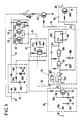
- FIG. 2 details an embodiment of the safety light unit 1 of the previous figure.
- Its supply circuit 10 connected to the sector 2 comprises a protection fuse 100, an isolation and voltage adaptation transformer 101 and a rectifier bridge 102.
- the charging circuit 12 of the storage battery 11 contains a PNP 120 type transistor mounted as a current source thanks to resistors 121, 122, 123, 124 and placed in series with a non-return diode 125.
- the transistor 120 maintains a substantially constant voltage across its emitter resistor 121 which is therefore crossed by a constant current.
- This constant current is used to charge the storage battery 11 which it arrives along a main path using the transistor 120, its collector resistor 122 and the isolation diode 125 and along a bypass path using the test lamp 132 , the two safety lamps 130 and 131 and the shunt resistors 133, 134.
- the passage of the charging current in the bypass path causes the test lamp to light up and thus ensures a self-test of the battery charge accumulators 11 and the good condition of the emergency lighting lamps 130 and 131.
- the management circuit of block 15 includes a circuit for detecting a cut in the normal supply controlling a repositionable bistable latch.
- the normal supply cut-off detection circuit is formed by an NPN transistor 160 mounted as a common emitter, polarized by a voltage divider bridge with resistors 161, 162 and supplied across a capacitor 163 charged by l by means of a non-return diode 164 and a resistor 165 by the voltage available at the output of the supply circuit 10 connected to the sector 2.
- the capacitor 163 charges sufficiently to polarize the transistor 160 at saturation and impose a collector voltage close to zero on it.
- the capacitor 163 discharges through the emitter collector circuit of the transistor 160 until the latter is blocked; there then appears a voltage spike at the collector of transistor 160 which is used to change the state of the flip-flop.
- the resistor 165 placed in front of the diode 164 limits the charging current of the capacitor 163 and also allows the anode of the diode 164 to be grounded by the inhibit input 20 to simulate a power cut. normal without, however, short-circuiting the output of the supply circuit 10.
- the flip-flop is formed by two complementary transistors res 170, 171 mounted as a common transmitter at the terminals of the storage battery 11 each controlling by their collector a resistive bridge 172, 173 or 174, 175 ensuring the base polarization of the other so as to be simultaneously blocked or saturated.
- the collector of the PNP type transistor 171 constitutes the output 19 of the block management circuit which controls the excitation of the relay closing the controlled switch 14.
- the normal power cut detection circuit controls the polarization of the base of the flip-flop transistor 170.
- the normal supply cut-off detection circuit imposes on the base of the transistor 170 of the flip-flop a voltage close to zero which has the effect of blocking this transistor 170 and consequently the other transistor 171 of the rocker.
- the transistor 171 being blocked, the coil of the relay of the controlled switch 14 is not supplied; the latter is open and the safety lamps 130, 131 are not connected to the terminals of the storage battery 11.
- the emergency lighting unit is in standby state, with its emergency lighting lamps off and its battery receiving charging current.
- the normal supply interruption detection circuit In the event of mains supply failure, the normal supply interruption detection circuit generates on its output a positive voltage pulse which saturates the transistor 170 of the flip-flop which causes the saturation of the transistor 171 and the excitation of the coil of the relay of the controlled switch 14 which closes connecting the safety lamps 130, 131 to the terminals of the storage battery 11 and bringing the safety lighting unit to the operating state, with its emergency lighting lights on.
- the output of the cut-off detection circuit of the normal supply has a sufficient impedance not to cause re-blocking of the transistor 170 maintained at saturation by 'Another transistor 171.
- the two transistors 170 and 171 of the flip-flop remain in the saturated state maintaining the emergency lighting unit in its operating state.
- the remote control input 18 is connected by a resistor 180 to the base of the transistor 170 of the flip-flop of the block management circuit 15. It allows, in the absence of mains supply, to block or saturate the transistor 170 by absorbing or by injecting by the resistor 180 a current in the emitter base junction of this transistor and consequently of controlling the state of the rocker i.e. the operating or rest state of the lighting unit of security.
- FIG. 3 details an embodiment of the autonomy test device 3 of FIG. 1.
- the time counter 30 is produced from a digital counter 300, from a lockable oscillator formed by two logic gates of type "and not” 304, 305 placed in oscillating regime by a network of resistors and capacity and a bistable type rocker R S formed by two logic gates of type "and not” 306, 207.
- the digital counter 300 has a counting input 301, a reset input 302 sensitive to positive pulses and an output whose most significant bit constitutes that of display 34 of the time counter 30.
- the type flip-flop R S determines the blocking or unblocking state of the time counter 30. It is connected by its output Q which constitutes the state output 33 of the time counter 30 to the blocking or unblocking control of the oscillator, to the circuit simulation 36 and, via a pulse generator with resistance 308 and capacity 309, at the reset input of the digital counter 300. Its input S constitutes the trigger input 31 of the time counter 30 while its input R constitutes that for blocking 32 of the time counter 30.
- the passage of its output Q from logic level 0 to logic level 1 unlocks the oscillator and causes the appearance of a positive pulse resetting the digital counter 300 while the passage inverse from logic level 1 to logic level 0 blocks the oscillator and generates a negative pulse with no effect on resetting the digital counter 300.
- the logic gate of the “no or” type 37 with two inputs which transforms the time counter 30 into a timer while allowing it to be blocked in the state by stopping the emergency lighting unit is formed, conventionally, by a transistor 370 mounted as a common transmitter and attacked by two resistors 371, 372 connecting its base, one to the display output 34 of the time counter 30 and the other to the output 21 of the current measurement circuit 45.
- the current measurement circuit 45 includes a reference voltage source determining the threshold of two threshold detectors each receiving as input the voltage developed across a shunt resistor 133, 134 by the current flowing through each emergency lighting lamp 130, 131.
- the reference voltage source is formed by the emitter base junction of a PNP type transistor 451 having its base connected to its collector, its emitter connected at 41 to the positive pole of the storage battery 11 in the company of one of the ends of the shunt resistors 133, 134 and its collector connected via a bias resistor 452 to ground, that is to say to the negative pole of the storage battery 11.
- Each threshold detector includes a PNP type transistor 453, 454 connected by its emitter at 42 or 43 at the connection point between a security lighting lamp 130, 131 and its shunt resistor 133, 134, by its base at the base. of the transitor 451 of the reference voltage source and by its collector at the output 21 of the current measurement circuit 45.
- the currents passing through them cause small voltage drops in the shunt resistors 133, 134 which block the transistors 453, 454 by making the voltage of their base emitter junction lower than that of the base emitter junction of transistor 451 of the reference voltage source.
- the collectors of the transistors 453, 454 which are joined together to form the output 21 of the current measurement circuit 45 are then in a state of high impedance and do not deliver any current.
- the simulation circuit 36 is produced using a transistor 360 mounted as a switch between the ground and the inhibition input 20 of the block management circuit.
- the remote control order reception circuit 38 is formed by a resistive voltage divider bridge 380, 381, connected between earth and the remote control input 18, provided with a reverse protection diode 382 and followed by a transistor stage 383 mounted as a common emitter.
- the indicator 35 is a light-emitting diode supplied by the sector and, placed in series with a current limiting resistor 350 and the emitter collector space of a transistor 351 controlled as a switch by the display output 34 of the time counter 30 between the ground and the outlet 40 of the supply circuit of the emergency lighting unit.
- the supply circuit 39 of the test device comprises a voltage regulation assembly formed by a Zener diode 390 connected in series with a resistor 391 across a capacitor filtering 392 charged, in the event of normal supply, by the sector thanks to a diode 393 connecting it to the output 40 of the supply circuit of the emergency lighting unit and, in the absence of normal supply, by the accumulator battery 11 of the emergency lighting unit thanks to a diode 394 connected at 41 to the latter.
- the test device is thus constantly supplied regardless of the standby, operating or resting state of the emergency lighting unit, either by the energy supplied by the normal supply, or by that, even residual, of the storage battery after full autonomy.
- the transistor 383 of the test remote control order reception circuit is blocked in the absence of voltage on the remote control input 18 or in the presence on this remote control input 18 of remote control extinction pulses from the block.
- emergency or re-ignition lighting because the first are of negative polarity and the second of insufficient voltage, for example 12 volts to unblock the base emitter junction of transistor 383 via the resistive divider bridge 380, 381.
- this transistor 383 becomes saturated during the application to the remote control input of a test remote control pulse of the same polarity as a remote control for re-lighting the block but of sufficient voltage, for example 24 volts, to generate at the output of the reception circuit test remote control command 38 a logic level 0 triggering the autonomy test.
- This logic level 0 in fact causes the passage to logic level 1 of the output Q of the flip-flop.
- R S formed by logic gates 306, 307 which has the effect: - the sending of a positive pulse by the resistance and capacitance network 308, 309 to the reset input of the digital counter 300 whose output, including its most significant bit, goes to zero, - switching on the transistor 360 of the simulation circuit 36, - unlocking the oscillator formed by logic gates 304, 305.
- the switching on of the transistor 360 of the simulation circuit 36 simulates for the management circuit of the emergency lighting unit a cut of the normal supply so that the complementary transistors 170, 171 (FIG. 2) of the latter pass s '' they were not already in the conduction state and excite the coil of the relay constituting the controlled switch 14 ( Figure 2) which closes and causes the illumination of the emergency lighting lamps 130, 131 from of the storage battery.
- the emergency lighting unit goes into operating state.
- the transition to the operating state is directly caused by the polarization of the transistor 170 by the resistor 180 and the conduction of the transistor 360 prohibits the return to the standby state in the event of restoration of the normal supply during the autonomy test.
- the lighting of the emergency lighting lamps 130, 131 following the closing of the controlled switch 14, causes the appearance of voltage across the shunt resistors 133, 134 which block the transistors 453, 454 and pass the output 21 of circuit 45 for measuring current at logic level 0.
- the output of logic gate "no or" 37 switches to logic level 1 and maintains the type flip-flop in the state R S formed by the logic gates 306, 307, even after returning to logic level 1 of the output of the remote control command reception circuit 38.
- the unlocking of the oscillator formed by the logic gates 306, 307 causes the emission of periodic pulses counted by the digital counter 300 which having been reset at the start of the test counts the time elapsed.
- the end of the test can be caused by the fact that the test took place over the planned duration or by the arrival at the end of discharge of the storage battery or by a bad operation of one of the emergency lighting lamps.
- the passage of time corresponding to the duration planned for the test is attested by the passage of the most significant bit of the output of the digital counter 300 to the logic state 1, the frequency of the oscillator and the capacity of the digital counter having been chosen accordingly while the end of discharge of the storage battery or the malfunction of one of the emergency lighting lamps is attested by the passage to logic level 1 of the output 21 of the measurement circuit 45 of current this passage being due to the opening of the controlled switch 14 as a result of the blocking of the complementary transistors 170, 171 due to insufficient polarization by the storage battery or to the malfunction of one of the lamps d 'safety lighting.
- the blocking of the simulation circuit 36 allows the capacitor 163 (FIG. 2) of the block management circuit to recharge and unblock the transistor 160 which controls the blocking, if it was not already there, of the complementary transistors 170 and 171, the excitation stop of the relay of the controlled switch 14 and therefore the extinction of the emergency lighting lamps.
- the emergency lighting unit returns to the standby state and the battery returns to charging.
- the blocking of the oscillator formed by the logic gates 304 and 305 leaves the digital counter 300 in the state.
- Two cases are possible: - the end of the test was caused by the current measurement circuit.
- the digit with the highest weight of the output of the digital counter 300 has remained at logic level 0 showing that the real autonomy of the emergency lighting unit does not reach the autonomy nominal.
- the light-emitting diode of the indicator 35 is not supplied and remains off, indicating a negative test, - the end of the test was caused by the change to digital level 1 of the most significant digit of the output of the digital counter 300 showing that the test was prolonged for the desired duration without reaching the end of battery discharge d 'Accumulators.
- the transistor 351 is then saturated and the light-emitting diode of the indicator light 35 lit in the presence of normal power supply indicating a positive test.
- the state of the light-emitting diode of the indicator 35 remains unchanged between two autonomy tests.
- the autonomy tests are carried out normally in the presence of normal power and, to determine the maximum duration of the test, it must be taken into account that the accumulator battery in the block continues to be charged even though it is not when the emergency light unit is in normal operation.
- This maximum test duration must then be greater than the nominal autonomy of the block in the range of 10 to 30% for accumulator batteries receiving a charging current corresponding to a charge in 24 hours and discharging in 1 at 3 o'clock in the security lights.
- the autonomy test is only valid if the normal power supply has been present long enough between the last autonomy and the start of the test and if the test has not been canceled before its end by an extinguishing remote control.
Landscapes
- Engineering & Computer Science (AREA)
- Power Engineering (AREA)
- Physics & Mathematics (AREA)
- General Physics & Mathematics (AREA)
- Business, Economics & Management (AREA)
- Emergency Management (AREA)
- Circuit Arrangement For Electric Light Sources In General (AREA)
Applications Claiming Priority (2)
| Application Number | Priority Date | Filing Date | Title |
|---|---|---|---|
| FR8806795 | 1988-05-20 | ||
| FR8806795A FR2631754B1 (fr) | 1988-05-20 | 1988-05-20 | Appareil de test d'autonomie pour bloc d'eclairage de securite |
Publications (1)
| Publication Number | Publication Date |
|---|---|
| EP0342579A1 true EP0342579A1 (de) | 1989-11-23 |
Family
ID=9366493
Family Applications (1)
| Application Number | Title | Priority Date | Filing Date |
|---|---|---|---|
| EP89108732A Ceased EP0342579A1 (de) | 1988-05-20 | 1989-05-16 | Vorrichtung für den Autonomietest bei Notbeleuchtungsblöcken |
Country Status (3)
| Country | Link |
|---|---|
| EP (1) | EP0342579A1 (de) |
| FR (1) | FR2631754B1 (de) |
| NO (1) | NO891990L (de) |
Cited By (5)
| Publication number | Priority date | Publication date | Assignee | Title |
|---|---|---|---|---|
| FR2658010A1 (fr) * | 1990-02-08 | 1991-08-09 | Sgs Thomson Microelectronics | Systeme d'eclairage de secours pour installations alimentees par un reseau electrique. |
| FR2665032A1 (fr) * | 1990-07-17 | 1992-01-24 | Legrand Sa | Coffret de telecommande pour bloc autonome d'eclairage de securite. |
| EP0780821A3 (de) * | 1995-12-21 | 1998-04-08 | Hubbell Incorporated | Funkgesteuertes System zur Überprüfung von Notbeleuchtungsblöcken |
| GB2380620A (en) * | 2001-07-07 | 2003-04-09 | Paul Alexander Breen | Automatic emergency lamp testing unit |
| FR2999353A1 (fr) * | 2012-12-12 | 2014-06-13 | Cooper Technologies Co | Dispositif d'eclairage de securite a autonomie amelioree |
Citations (5)
| Publication number | Priority date | Publication date | Assignee | Title |
|---|---|---|---|---|
| EP0030154A1 (de) * | 1979-12-04 | 1981-06-10 | Emlux Limited | Prüfung einer Notbatterie-Ausrüstung |
| DE3213003C1 (de) * | 1982-04-07 | 1983-08-11 | Theo Benning Elektrotechnik Und Elektronik Gmbh & Co Kg, 4290 Bocholt | Einrichtung zur Prüfung der Verfügbarkeit von Batterien in Notstromanlagen |
| EP0171629A1 (de) * | 1984-07-18 | 1986-02-19 | Société Anonyme dite SAFT | Vorrichtung zur Prüfung der Restkapazität von einem Sicherheitsbeleuchtungsaggregat |
| EP0206488A1 (de) * | 1985-05-14 | 1986-12-30 | Salplex Limited | Verfahren und Vorrichtung zur elektrischen Strommessung |
| EP0225106A1 (de) * | 1985-11-19 | 1987-06-10 | British Aerospace Public Limited Company | Anzeigegerät für den Ladezustand einer Batterie |
-
1988
- 1988-05-20 FR FR8806795A patent/FR2631754B1/fr not_active Expired - Fee Related
-
1989
- 1989-05-16 EP EP89108732A patent/EP0342579A1/de not_active Ceased
- 1989-05-18 NO NO89891990A patent/NO891990L/no unknown
Patent Citations (5)
| Publication number | Priority date | Publication date | Assignee | Title |
|---|---|---|---|---|
| EP0030154A1 (de) * | 1979-12-04 | 1981-06-10 | Emlux Limited | Prüfung einer Notbatterie-Ausrüstung |
| DE3213003C1 (de) * | 1982-04-07 | 1983-08-11 | Theo Benning Elektrotechnik Und Elektronik Gmbh & Co Kg, 4290 Bocholt | Einrichtung zur Prüfung der Verfügbarkeit von Batterien in Notstromanlagen |
| EP0171629A1 (de) * | 1984-07-18 | 1986-02-19 | Société Anonyme dite SAFT | Vorrichtung zur Prüfung der Restkapazität von einem Sicherheitsbeleuchtungsaggregat |
| EP0206488A1 (de) * | 1985-05-14 | 1986-12-30 | Salplex Limited | Verfahren und Vorrichtung zur elektrischen Strommessung |
| EP0225106A1 (de) * | 1985-11-19 | 1987-06-10 | British Aerospace Public Limited Company | Anzeigegerät für den Ladezustand einer Batterie |
Cited By (6)
| Publication number | Priority date | Publication date | Assignee | Title |
|---|---|---|---|---|
| FR2658010A1 (fr) * | 1990-02-08 | 1991-08-09 | Sgs Thomson Microelectronics | Systeme d'eclairage de secours pour installations alimentees par un reseau electrique. |
| FR2665032A1 (fr) * | 1990-07-17 | 1992-01-24 | Legrand Sa | Coffret de telecommande pour bloc autonome d'eclairage de securite. |
| EP0780821A3 (de) * | 1995-12-21 | 1998-04-08 | Hubbell Incorporated | Funkgesteuertes System zur Überprüfung von Notbeleuchtungsblöcken |
| US5929781A (en) * | 1995-12-21 | 1999-07-27 | Hubbell Incorporated | Radio frequency controlled system for testing emergency lighting units |
| GB2380620A (en) * | 2001-07-07 | 2003-04-09 | Paul Alexander Breen | Automatic emergency lamp testing unit |
| FR2999353A1 (fr) * | 2012-12-12 | 2014-06-13 | Cooper Technologies Co | Dispositif d'eclairage de securite a autonomie amelioree |
Also Published As
| Publication number | Publication date |
|---|---|
| NO891990L (no) | 1989-11-21 |
| FR2631754A1 (fr) | 1989-11-24 |
| FR2631754B1 (fr) | 1993-07-30 |
| NO891990D0 (no) | 1989-05-18 |
Similar Documents
| Publication | Publication Date | Title |
|---|---|---|
| CH669057A5 (fr) | Installation de surveillance et d'alarme. | |
| EP0342579A1 (de) | Vorrichtung für den Autonomietest bei Notbeleuchtungsblöcken | |
| EP0171629B1 (de) | Vorrichtung zur Prüfung der Restkapazität von einem Sicherheitsbeleuchtungsaggregat | |
| CH625962A5 (de) | ||
| EP0715172B1 (de) | Testgerät für geerdete Wandsteckdose | |
| EP0524300A1 (de) | Vorrichtung zum schutz von elektrischen geräten, maschinen und anlagen | |
| EP0029631B1 (de) | Für die Eisenbahnsignalisierung verwendbarer elektronischer Sicherheitsspeicher | |
| EP0067089B1 (de) | Beleuchtungskontrollanlage mit Speicher | |
| EP0536058B2 (de) | Elektronischer Auslöser mit lokale den detektierten Fehler anzeigende Mittel | |
| FR2548413A1 (fr) | Procedes et dispositifs pour eviter des fraudes sur un taxi equipe d'un repetiteur lumineux | |
| FR2658010A1 (fr) | Systeme d'eclairage de secours pour installations alimentees par un reseau electrique. | |
| EP0597746B1 (de) | Prüfgerät für Steckdose mit Erdung und Differentialschutz | |
| FR2719947A1 (fr) | Procédé et dispositif d'entretien d'un accumulateur utilisé en marche flottante, notamment pour un appareil de sécurité. | |
| EP0253709A1 (de) | Überwachungsanlage mit in einer Schleife gespeisten Detektoren | |
| EP1014100B1 (de) | Anordung zur Ermittlung einer Unterbrechung in einer elektrischen Leitung, inbesondere einer Telefonleitung | |
| FR2616929A1 (fr) | Dispositif de commande de test d'autonomie pour un ensemble de blocs d'eclairage de securite | |
| FR2598829A1 (fr) | Dispositif de commande domestique a usage general. | |
| FR2604324A1 (fr) | Cloture electrique sensitive | |
| FR2638585A1 (fr) | Chargeur pour accumulateur cadmium-nickel | |
| FR2582411A1 (fr) | Detecteur differentiel a fonctionnement verifiable quelle que soit la position de la cible | |
| FR2535930A1 (fr) | Ensemble portatif autonome pour le controle d'equipement d'eclairage public | |
| EP0290314B1 (de) | Ansteuerschaltung für elektrische Fernbedienungsapparate, besonders Fernauslöser und Apparate, die diese Schaltung enthalten | |
| FR2466813A1 (fr) | Avertisseur sonore electronique autonome et installation correspondante | |
| FR2652222A1 (fr) | Dispositif de surveillance a distance de l'alimentation en courant d'un appareil electrique. | |
| FR2555340A1 (fr) | Centrale d'alarme |
Legal Events
| Date | Code | Title | Description |
|---|---|---|---|
| PUAI | Public reference made under article 153(3) epc to a published international application that has entered the european phase |
Free format text: ORIGINAL CODE: 0009012 |
|
| AK | Designated contracting states |
Kind code of ref document: A1 Designated state(s): AT BE CH DE ES FR GB IT LI LU NL SE |
|
| 17P | Request for examination filed |
Effective date: 19900514 |
|
| RAP1 | Party data changed (applicant data changed or rights of an application transferred) |
Owner name: SAFT |
|
| 17Q | First examination report despatched |
Effective date: 19920525 |
|
| STAA | Information on the status of an ep patent application or granted ep patent |
Free format text: STATUS: THE APPLICATION HAS BEEN REFUSED |
|
| 18R | Application refused |
Effective date: 19930211 |