EP0342452A1 - Moteur à induction monophasé avec enroulement à un toron - Google Patents
Moteur à induction monophasé avec enroulement à un toron Download PDFInfo
- Publication number
- EP0342452A1 EP0342452A1 EP89108150A EP89108150A EP0342452A1 EP 0342452 A1 EP0342452 A1 EP 0342452A1 EP 89108150 A EP89108150 A EP 89108150A EP 89108150 A EP89108150 A EP 89108150A EP 0342452 A1 EP0342452 A1 EP 0342452A1
- Authority
- EP
- European Patent Office
- Prior art keywords
- winding
- rotor
- stator
- motor according
- control
- Prior art date
- Legal status (The legal status is an assumption and is not a legal conclusion. Google has not performed a legal analysis and makes no representation as to the accuracy of the status listed.)
- Withdrawn
Links
- 238000004804 winding Methods 0.000 title claims abstract description 82
- 230000006698 induction Effects 0.000 title claims abstract description 5
- 239000004065 semiconductor Substances 0.000 claims abstract description 5
- 230000005291 magnetic effect Effects 0.000 claims description 7
- 230000001419 dependent effect Effects 0.000 claims description 2
- 238000010586 diagram Methods 0.000 description 6
- 239000003990 capacitor Substances 0.000 description 3
- 229910000831 Steel Inorganic materials 0.000 description 2
- 238000010276 construction Methods 0.000 description 2
- 230000002349 favourable effect Effects 0.000 description 2
- 230000004907 flux Effects 0.000 description 2
- 230000004048 modification Effects 0.000 description 2
- 238000012986 modification Methods 0.000 description 2
- 239000010959 steel Substances 0.000 description 2
- OKTJSMMVPCPJKN-UHFFFAOYSA-N Carbon Chemical compound [C] OKTJSMMVPCPJKN-UHFFFAOYSA-N 0.000 description 1
- 230000003321 amplification Effects 0.000 description 1
- 229910052799 carbon Inorganic materials 0.000 description 1
- 238000006243 chemical reaction Methods 0.000 description 1
- 238000003199 nucleic acid amplification method Methods 0.000 description 1
- 238000010791 quenching Methods 0.000 description 1
- 230000000171 quenching effect Effects 0.000 description 1
- 239000000523 sample Substances 0.000 description 1
Images


Classifications
-
- H—ELECTRICITY
- H02—GENERATION; CONVERSION OR DISTRIBUTION OF ELECTRIC POWER
- H02K—DYNAMO-ELECTRIC MACHINES
- H02K17/00—Asynchronous induction motors; Asynchronous induction generators
- H02K17/02—Asynchronous induction motors
- H02K17/30—Structural association of asynchronous induction motors with auxiliary electric devices influencing the characteristics of the motor or controlling the motor, e.g. with impedances or switches
-
- H—ELECTRICITY
- H02—GENERATION; CONVERSION OR DISTRIBUTION OF ELECTRIC POWER
- H02P—CONTROL OR REGULATION OF ELECTRIC MOTORS, ELECTRIC GENERATORS OR DYNAMO-ELECTRIC CONVERTERS; CONTROLLING TRANSFORMERS, REACTORS OR CHOKE COILS
- H02P25/00—Arrangements or methods for the control of AC motors characterised by the kind of AC motor or by structural details
- H02P25/02—Arrangements or methods for the control of AC motors characterised by the kind of AC motor or by structural details characterised by the kind of motor
- H02P25/04—Single phase motors, e.g. capacitor motors
Definitions
- the invention relates to a single-phase induction motor with a single-strand stator winding, which generates an alternating field, with a rotor with one or more winding phases, which are only switched on in the torque-generating angle range.
- Motors that belong to this generic term are known, for example, as repulsion motors. These motors have - in common with all current band motors - the main disadvantages that they require a power inverter and carbon brushes, which are worn out after about 2000 hours of operation and produce a loud operating noise.
- the object of the present invention is to provide an electric motor which achieves high speeds without speed limitation, runs quietly and can be produced inexpensively, the higher speeds resulting in the same output for a more compact design and such motors can also be used, for example, to drive compact fans or pumps.
- At least one self-contained rotor winding strand is designed, which has a controllable semiconductor housed on the rotor, preferably a triac, with each rotor winding strand coming into a rotating winding serves to generate torque and a control winding, which has the primary task of switching on the triac, is divided, and in this case the control winding, in order to determine the direction of rotation, is arranged at an angle of up to approximately 70 degrees with respect to the rotation winding against the direction of rotation.
- the triac of the respective rotor winding strand and with it the current flow are switched on when the rotary winding is at an angle of rotation of approximately 10 to 45 degrees above its horizontal position transversely to the stator flux, the rotary winding in the angle of rotation range of approximately 10 to 80 Degrees torque-generating endeavor to cover both legs in the stator flux, because in this position the coil current has its lowest value.
- the triac therefore switches off automatically in this position.
- the rotor will reach a maximum speed of approx. 46 U / s.
- the AC line voltage is cut using known phase gating at phase angles of around 90/270 degrees, the maximum speed will reach approx. 100 U / s, because the gaps in the stator current flow and its new rise and fall act on this motor as a doubled frequency, using a potentiometer the switched on phases reduced the area and thus the speed can be reduced.
- the phase gating reduces the flowing current, the number of turns of the stator winding must be reduced to compensate; this means that the number of turns of the rotor windings can also be reduced with the same voltage ratio.
- the inductance is advantageously reduced with the reduced number of turns.
- a four-way rectifier is connected in front of the stator winding and the two stator coils usually present are assigned to separate circuits in such a way that they are alternately switched on, for example by means of a known inverter circuit with two thyristors and an extinguishing capacitor, the two stator coils being connected in such a way that their currents flow in opposite directions. they cause an alternating field in the stator at the frequency with which the two inverter thyristors are switched on and thus a correspondingly high rotor speed.
- a high switching sequence with resistance and capacitor can be achieved at each gate or diag, as is known for phase gates.
- the thyristors of the inverter can be switched on alternately, for example by means of an astable multivibrator.
- the control winding can be connected on the one hand via a diag at the gate and on the other hand at connection A1 of the triac or on the other hand at connection A2 of the triac, whereby in both cases the resistance of the control winding and gate or diag can be used to set the gate current to the desired turn-on position .
- a control rotor can be used for the control coil or the control coils on the same shaft, which means that an optimum switch-on angle position and more winding space for the rotary windings can be achieved independently of the rotor slots.
- Primary windings that are spatially separated from the stator winding can be used for this.
- a photoelectronic semiconductor can also be connected on the rotor in front of the gate or the diag, which, in cooperation with a light source attached to the stator, switches on the triac in the optimum rotational angle position for the motor torque.
- a magnetic field-dependent sensor for example a Hall probe with the necessary amplification means, can be connected in front of the gate or diag, the sensor being arranged on the rotor shaft outside the stator field and a magnet connected to the stator, which is in the sensor then generates a signal causing the triac to turn on when the rotary winding is in the optimum torque-generating rotational angle position.
- means can be provided which hold the rotor in a standstill by magnetic action in a position which is favorable for starting.
- Such means are known in principle.
- they are characterized by a multi-toothed part arranged on the rotor shaft and having as many diagonal tooth pairs as rotor winding strands, the angular position between the pair of teeth and a counterpole or counterpole pair arranged on the stator, on the one hand, and the rotor winding phases, on the other hand, is selected such that the rotor is held at a standstill in such an angular position that one of its winding phases is in its switch-on range.
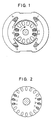
- 1 and 2 represent the stator winding.
- the rotary winding 3 and the control winding 4 are drawn in the angular position, in which turns on a triac 5, causing the rotor to rotate about 70 degrees in the direction of the arrow.
- Only one winding phase is shown. Additional winding strands can be accommodated in the empty slots, each of which rotates the rotor by approximately 75 degrees. Because after 180 degrees the winding strands come back into their effective range, the rotor turns continuously.
- the rotary winding 3 is accommodated in four rotor slots to increase the torque. Additional winding strands can also be accommodated in the slots marked empty.
- phase gating 8 in addition to the two stator windings 1 and 2, the internal circuit of the phase gating being known.
- the resistor 7 shows how the rotating coil 3, the control coil 4, the triac 5, the diag 6 and the resistor 7 are advantageously switched.
- the sum of the voltage induced in the rotary winding 3 and the control winding 4 is present between A1 / A2 of the triac 5.
- the voltage induced in the control winding 4 is available at the gate of the triac 5.
- the resistor 7 is dimensioned such that the triac 5 is switched on when the rotating coil has reached the rotational position shown in FIG. 1. As soon as the triac 5 is switched on, the sum of the induced current flows through it and the two windings 3 and 4 and causes the torque.
- Fig. 6 shows another modification of the rotor winding, in which the control winding 4 is connected between the gate and terminal A2 of the triac 5.
- FIG. 7 shows a modified stator winding in which the AC line voltage is converted into pulsating DC voltage by a four-way rectifier 9 and then divided between the stator windings 1 and 2 by means of the two thyristors 10 and 11 and the quenching capacitor 12.
- the two stator windings 1 and 2 are connected in opposite directions according to the invention.
- the freewheeling diodes, swinging reactors and switch-on devices for the thyristors belonging to the known inverter circuits are not shown in detail for the sake of clarity.
- FIG. 8 shows the switched-on periods of arbitrarily selected frequencies for the stator windings 1 and 2 of FIG. 7.
- the filled-in fields above the abscissa show when the stator winding 1 is switched on.
- the filled-in fields below the abscissa show when stator winding 2 is switched on. Because stator winding 2 is mutually connected, it makes sense to indicate its current flow below the abscissa, because in the manner shown, which corresponds to an alternating current of higher frequency, the stator magnetic field is generated.
- means can be provided which hold the stator in a standstill by means of a magnetic effect in a position which is favorable for starting.
- the position number 15 in FIG. 9 represents the multi-toothed part on the rotor shaft, 16 shows a permanent magnetic opposite pole, together with 17 the opposite pole pair, 18 represents the stator.
- the multi-toothed part 15 is designed with as many diagonal tooth pairs as rotor winding strands.
- the angular position between the pair of teeth and the opposing pole 16 or the Ge arranged on the stator 18 Genpolpres 17 on the one hand and the rotor winding strands on the other hand is selected so that the rotor is held at a standstill in such a rotational angle position that one of its winding strands is always in its switch-on range.
- a particularly simple construction results when a multi-toothed sheet steel part with angled teeth is arranged on the rotor and a permanent magnet on the stator.
Landscapes
- Engineering & Computer Science (AREA)
- Power Engineering (AREA)
- Control Of Ac Motors In General (AREA)
- Permanent Magnet Type Synchronous Machine (AREA)
- Induction Machinery (AREA)
Applications Claiming Priority (2)
| Application Number | Priority Date | Filing Date | Title |
|---|---|---|---|
| DE3815737 | 1988-05-07 | ||
| DE19883815737 DE3815737A1 (de) | 1988-05-07 | 1988-05-07 | Einphasen-induktionsmotor mit steuernden halbleitern am rotor |
Publications (1)
| Publication Number | Publication Date |
|---|---|
| EP0342452A1 true EP0342452A1 (fr) | 1989-11-23 |
Family
ID=6353945
Family Applications (1)
| Application Number | Title | Priority Date | Filing Date |
|---|---|---|---|
| EP89108150A Withdrawn EP0342452A1 (fr) | 1988-05-07 | 1989-05-05 | Moteur à induction monophasé avec enroulement à un toron |
Country Status (4)
| Country | Link |
|---|---|
| EP (1) | EP0342452A1 (fr) |
| JP (1) | JPH02504220A (fr) |
| DE (1) | DE3815737A1 (fr) |
| WO (1) | WO1989011177A1 (fr) |
Families Citing this family (1)
| Publication number | Priority date | Publication date | Assignee | Title |
|---|---|---|---|---|
| FR2755548B1 (fr) * | 1996-11-07 | 1998-12-18 | Ksb Sa | Circuit d'alimentation d'un moteur asynchrone triphase a partir d'une source de tension monophasee |
Citations (3)
| Publication number | Priority date | Publication date | Assignee | Title |
|---|---|---|---|---|
| FR2150509A1 (fr) * | 1971-08-25 | 1973-04-06 | Nipkiep | |
| DE2233784A1 (de) * | 1972-07-06 | 1974-01-17 | Hubert Smidt | Regelsatz mit stufenlos regelbarem asynchronmotor |
| GB1404154A (en) * | 1972-11-24 | 1975-08-28 | Geraetewerk Karl Marx Stadt Im | Starting arrangement for electronically controlled single-phase asynchronous motors primarily for teleprinters |
Family Cites Families (1)
| Publication number | Priority date | Publication date | Assignee | Title |
|---|---|---|---|---|
| JPS5653563A (en) * | 1979-10-05 | 1981-05-13 | Hideo Konase | Rotor of induction motor loading gap reactor and capacitor |
-
1988
- 1988-05-07 DE DE19883815737 patent/DE3815737A1/de not_active Withdrawn
-
1989
- 1989-05-05 EP EP89108150A patent/EP0342452A1/fr not_active Withdrawn
- 1989-05-05 WO PCT/DE1989/000284 patent/WO1989011177A1/fr not_active Ceased
- 1989-05-05 JP JP1504868A patent/JPH02504220A/ja active Pending
Patent Citations (3)
| Publication number | Priority date | Publication date | Assignee | Title |
|---|---|---|---|---|
| FR2150509A1 (fr) * | 1971-08-25 | 1973-04-06 | Nipkiep | |
| DE2233784A1 (de) * | 1972-07-06 | 1974-01-17 | Hubert Smidt | Regelsatz mit stufenlos regelbarem asynchronmotor |
| GB1404154A (en) * | 1972-11-24 | 1975-08-28 | Geraetewerk Karl Marx Stadt Im | Starting arrangement for electronically controlled single-phase asynchronous motors primarily for teleprinters |
Non-Patent Citations (1)
| Title |
|---|
| PATENT ABSTRACTS OF JAPAN vol. 5, no. 113 (E-66)(785) 22 Juli 1981, & JP-A-56 53563 (HIDEO KONASE) 13 Mai 1981, * |
Also Published As
| Publication number | Publication date |
|---|---|
| JPH02504220A (ja) | 1990-11-29 |
| DE3815737A1 (de) | 1989-11-16 |
| WO1989011177A1 (fr) | 1989-11-16 |
Similar Documents
| Publication | Publication Date | Title |
|---|---|---|
| DE3740725C2 (fr) | ||
| DE3490616C2 (fr) | ||
| DE69732119T2 (de) | Gleichstrom-permanentmagnetmaschine mit integrierter regelung der rekonfigurierbaren wicklung | |
| DE69201354T2 (de) | Synchronmotor mit zwei dauermagnetischen Läuferteilen. | |
| DE69916476T2 (de) | Synchronmaschine mit rotierenden bürsten | |
| WO2008148621A1 (fr) | Moteur électrique à rotor à excitation hybride | |
| DE102014102423A1 (de) | Elektrischer Antrieb mit rekonfigurierbarer Wicklung | |
| WO2002009261A1 (fr) | Machine unipolaire a flux transversal | |
| DE2305163A1 (de) | Buerstenloser gleichstrommotor | |
| DE2658998A1 (de) | Elektromotor | |
| DE2225442A1 (de) | Kollektorloser gleichstrom-motor | |
| DE2620935A1 (de) | Motor mit veraenderlichem magnetischen widerstand | |
| DE3122049A1 (de) | Kollektorloser gleichstromaussenlaeufermotor | |
| DE3933790C2 (de) | Elektrische Maschine mit einem Rotor und einem Stator | |
| DE2756575C2 (fr) | ||
| DE102020122142A1 (de) | Ein bürstenloser dc-dynamo und ein fahrzeug mit dem bürstenlosen dc-dynamo | |
| DE4036565C1 (en) | Electronic drive system using variable reluctance electric motor - slows down variations in magnetic induction of stator by electronic control of winding current | |
| DE102011081215A1 (de) | Drehstrommaschinen-Ansteuerungsverfahren und -vorrichtung | |
| EP0342452A1 (fr) | Moteur à induction monophasé avec enroulement à un toron | |
| DE2314259A1 (de) | Kollektorloser gleichstrommotor | |
| DE3530614A1 (de) | Buerstenlose induktionsmaschine | |
| DE10357503A1 (de) | Ansteuerung eines Gleichstrommotors | |
| DE102019004428A1 (de) | Elektronisch kommutierter Elektromotor | |
| DE2556582A1 (de) | Verfahren und motor-vorrichtung zur erzeugung hoher drehzahlen | |
| DE8808014U1 (de) | Einphasen-Induktionsmotor mit steuernden Halbleitern am Rotor |
Legal Events
| Date | Code | Title | Description |
|---|---|---|---|
| PUAI | Public reference made under article 153(3) epc to a published international application that has entered the european phase |
Free format text: ORIGINAL CODE: 0009012 |
|
| AK | Designated contracting states |
Kind code of ref document: A1 Designated state(s): CH DE FR GB IT LI SE |
|
| 17P | Request for examination filed |
Effective date: 19891215 |
|
| STAA | Information on the status of an ep patent application or granted ep patent |
Free format text: STATUS: THE APPLICATION IS DEEMED TO BE WITHDRAWN |
|
| 18D | Application deemed to be withdrawn |
Effective date: 19911203 |