EP0342270A1 - Anlasseranlage für Dieselmotoren - Google Patents
Anlasseranlage für Dieselmotoren Download PDFInfo
- Publication number
- EP0342270A1 EP0342270A1 EP88119413A EP88119413A EP0342270A1 EP 0342270 A1 EP0342270 A1 EP 0342270A1 EP 88119413 A EP88119413 A EP 88119413A EP 88119413 A EP88119413 A EP 88119413A EP 0342270 A1 EP0342270 A1 EP 0342270A1
- Authority
- EP
- European Patent Office
- Prior art keywords
- storage tank
- oil
- starter system
- oil storage
- engine
- Prior art date
- Legal status (The legal status is an assumption and is not a legal conclusion. Google has not performed a legal analysis and makes no representation as to the accuracy of the status listed.)
- Granted
Links
Images

Classifications
-
- F—MECHANICAL ENGINEERING; LIGHTING; HEATING; WEAPONS; BLASTING
- F02—COMBUSTION ENGINES; HOT-GAS OR COMBUSTION-PRODUCT ENGINE PLANTS
- F02N—STARTING OF COMBUSTION ENGINES; STARTING AIDS FOR SUCH ENGINES, NOT OTHERWISE PROVIDED FOR
- F02N19/00—Starting aids for combustion engines, not otherwise provided for
- F02N19/001—Arrangements thereof
-
- F—MECHANICAL ENGINEERING; LIGHTING; HEATING; WEAPONS; BLASTING
- F01—MACHINES OR ENGINES IN GENERAL; ENGINE PLANTS IN GENERAL; STEAM ENGINES
- F01M—LUBRICATING OF MACHINES OR ENGINES IN GENERAL; LUBRICATING INTERNAL COMBUSTION ENGINES; CRANKCASE VENTILATING
- F01M5/00—Heating, cooling, or controlling temperature of lubricant; Lubrication means facilitating engine starting
-
- F—MECHANICAL ENGINEERING; LIGHTING; HEATING; WEAPONS; BLASTING
- F01—MACHINES OR ENGINES IN GENERAL; ENGINE PLANTS IN GENERAL; STEAM ENGINES
- F01M—LUBRICATING OF MACHINES OR ENGINES IN GENERAL; LUBRICATING INTERNAL COMBUSTION ENGINES; CRANKCASE VENTILATING
- F01M9/00—Lubrication means having pertinent characteristics not provided for in, or of interest apart from, groups F01M1/00 - F01M7/00
- F01M9/10—Lubrication of valve gear or auxiliaries
- F01M9/106—Oil reservoirs
-
- F—MECHANICAL ENGINEERING; LIGHTING; HEATING; WEAPONS; BLASTING
- F02—COMBUSTION ENGINES; HOT-GAS OR COMBUSTION-PRODUCT ENGINE PLANTS
- F02B—INTERNAL-COMBUSTION PISTON ENGINES; COMBUSTION ENGINES IN GENERAL
- F02B3/00—Engines characterised by air compression and subsequent fuel addition
- F02B3/06—Engines characterised by air compression and subsequent fuel addition with compression ignition
Definitions
- This invention concerns a starter system for direct or indirect injection diesel-cycle engines of small or medium capacity, which provides for the introduction of a measured quantity of lubricating oil into the combustion chamber to assist start-up.
- This lubricating oil is the same as the oil circulating in the engine and held in the sump of the engine.
- the invention concerns a system to assist start-up of direct or indirect injection diesel engines of small or medium capacity, that is, up to 20/25 KW, even in very cold weather.
- One of these systems arranges that the combustion chamber can be put in communication with the exterior for start-up purposes by means of a conduit above the inlet valve.
- the inlet valve When the engine is turned over, the inlet valve is opened and the oil enters the combustion chamber, increases the compression ratio and, in cooperation with the piston rings, increases the hydraulic seal engagement of the piston.
- FR-A-2386696 discloses the idea of introducing a measured quantity of oil into the combustion chamber to assist start-up of multi-cylinder diesel engines.
- the executive art provides for the employment of an external reservoir and pump to inject oil into the combustion chamber at a very high pressure (about 200 atmospheres).
- DE-C-697824 discloses the idea of introducing a measured quantity of oil into the combustion chamber to reduce wear of the cylinder owing to corrosion (especially in marine engines) and not to assist start-up.
- the text refers generically to engines producing heat (not only diesel engines).
- the executive art provides for the employment of an external reservoir to introduce the oil into the combustion chamber through an induction manifold.
- DE-B-1218795 discloses the idea of introducing a measured quantity of oil into the combustion chamber through the induction manifold to assist start-up of an engine producing heat (generically). It provides for the inclusion of a pump and an external oil reservoir.
- US-A-3229678 discloses the idea of a device which introduces oil in a measured quantity into the combustion chamber of an engine producing heat (with special reference to marine engines), the purpose being to reduce wear of the cylinder due to corrosion, but the oil is introduced only after a pre-set period of time with a view to reducing the consumption of the oil.
- the executive art provides for an external reservoir and a pump.
- the present applicant has designed, tested and embodied this invention, in which the lubricating oil used is the same as that circulating in the lubricating circuit of the engine.
- the chamber above the inlet valve is connected, for instance by a connecting conduit, to an oil storage tank, closure valve means being interposed which are suitable to shut off the oil in the oil storage tank.
- the oil storage tank is advantageously, but not necessarily, located above the induction conduit.
- the oil is either introduced beforehand or is caused to arrive in a desired manner in the oil storage tank.
- the dimensions of the oil storage tank are such as to hold the required quantity of oil.
- the storage tank comprises an overflow to discharge any excess of oil advantageously into the drainage circuit of the lubricating oil.
- the storage tank is fed by the lubrication circuit which serves to take lubricating oil to the various parts of the engine.
- the storage tank is fed continuously by the lubrication circuit, whereas according to another variant it is fed periodically by the lubrication circuit.
- the lubrication circuit is connected to the storage tank through a gauged hole or choke so as to avoid losses of pressure in the lubrication circuit during normal use.
- the lubrication circuit is connected to the storage tank through a small pressure relief valve which allows oil to pass through only when the pressure in the lubrication circuit is higher than pre-set levels.
- closure valve means cooperate with the connecting conduit in shutting off the liquid in the oil storage tank and can be opened momentarily to allow the oil in the storage tank to flow out.
- the closure valve means consist of a wedge thrust resiliently against the outlet hole of the oil storage tank.
- the closure valve means can be actuated externally by grip means, which by overcoming the resistance of spring means put the storage tank in communication with the connecting cnduit, thus allowing the lubricating oil to flow out into the induction conduit above the inlet valve.
- the grip means are connected to an automatic actuator, which is switched on when the ignition key is inserted, so that upon the simple act of actuating the start-up of the engine the automatic actuator takes action in the storage tank and releases oil into the specific combustion chamber.
- the means of the solution are manifold in relation to the geometric design linked to the practical embodiment applied to the various requirements of engines.
- Fig.1 shows a possible head of an engine which contains, substantially at top dead centre, a piston 11 above which is a combustion chamber 10.
- An inlet valve 12 cooperates with the combustion chamber 10 and shuts an induction conduit 13.
- the induction conduit 13 is connected temporarily with the exterior through a connecting conduit 14 and an oil storage tank 24, which is closed momentarily by a plug 23.
- the plug 23 is removed for start-up and the desired quantity of oil is introduced with an appropriate oil can into the storage tank 24.
- the plug 23 is then replaced while the oil flows over the inlet valve 12; when the engine is rotated, the inlet valve 12 opens and the oil arrives in the combustion chamber 10, increases the compression ratio, flows down the sides of that chamber 10 and cooperates with the piston rings in improving the engagement seal of the chamber, thus enabling the minimum air temperature necessary for start-up to be reached.
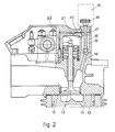
- Fig.2 shows a possible embodiment applied to an engine head substantially the same as that of Fig.1.
- Fig.2 shows not only a piston 11, combustion chamber 10, inlet valve 12, induction conduit 13 and connecting conduit 14 but also a storage tank 16 with an overflow 21, which returns any excess of oil within the engine into the lubrication circuit or return circuit for the lubricating oil.
- closure valve means 17 kept resiliently in the closed position by spring means 15.
- Grip means 18 are comprised on the exterior of the closure valve means 17 and permit manual actuation, that is, the lifting of the closure valve means 17 and the communication of the storage tank 16 with the connecting conduit 14.
- the storage tank 16 is connected to a lubrication circuit 22 through a choke 20.
- the dimensions of the choke 20 are such as to prevent excessively great losses of pressure occurring in the lubrication circuit 22.
- a pressure relief valve may be comprised which permits oil to reach the storage tank 16 only when desired pressures have been reached within the lubrication circuit 22.
- the grip means 18 cooperate with an automatic actuator 19 governed by the start-up of the engine.
- This automatic actuator 19 may be a solenoid or another means suitable for the purpose.
Landscapes
- Engineering & Computer Science (AREA)
- Mechanical Engineering (AREA)
- General Engineering & Computer Science (AREA)
- Chemical & Material Sciences (AREA)
- Combustion & Propulsion (AREA)
- Lubrication Of Internal Combustion Engines (AREA)
- Valve Device For Special Equipments (AREA)
- Output Control And Ontrol Of Special Type Engine (AREA)
Priority Applications (1)
| Application Number | Priority Date | Filing Date | Title |
|---|---|---|---|
| AT88119413T ATE70597T1 (de) | 1988-05-16 | 1988-11-22 | Anlasseranlage fuer dieselmotoren. |
Applications Claiming Priority (2)
| Application Number | Priority Date | Filing Date | Title |
|---|---|---|---|
| IT8339088 | 1988-05-16 | ||
| IT8883390A IT1226453B (it) | 1988-05-16 | 1988-05-16 | Starter per motori diesel. |
Publications (2)
| Publication Number | Publication Date |
|---|---|
| EP0342270A1 true EP0342270A1 (de) | 1989-11-23 |
| EP0342270B1 EP0342270B1 (de) | 1991-12-18 |
Family
ID=11321175
Family Applications (1)
| Application Number | Title | Priority Date | Filing Date |
|---|---|---|---|
| EP88119413A Expired - Lifetime EP0342270B1 (de) | 1988-05-16 | 1988-11-22 | Anlasseranlage für Dieselmotoren |
Country Status (4)
| Country | Link |
|---|---|
| EP (1) | EP0342270B1 (de) |
| AT (1) | ATE70597T1 (de) |
| DE (1) | DE3867062D1 (de) |
| IT (1) | IT1226453B (de) |
Cited By (1)
| Publication number | Priority date | Publication date | Assignee | Title |
|---|---|---|---|---|
| EP0814259A1 (de) * | 1996-06-19 | 1997-12-29 | Motorenfabrik Hatz GmbH & Co. KG | Kaltstartvorrichtung |
Citations (4)
| Publication number | Priority date | Publication date | Assignee | Title |
|---|---|---|---|---|
| DE697824C (de) * | 1937-11-05 | 1940-10-24 | C & S Clementson | Einrichtung zur selbsttaetigen Zufuehrung einer zusaetzlichen Schmieroelmenge beim Anlassen von Brennkraftmaschinen |
| US3229678A (en) * | 1965-06-08 | 1966-01-18 | Roy L Anspach | Lubricating device |
| DE1218795B (de) * | 1960-04-05 | 1966-06-08 | Josef Eicher | Einrichtung zum Erhoehen des Verdichtungs-verhaeltnisses beim Anlassen von Hubkolben-Brennkraftmaschinen |
| FR2386696A1 (fr) * | 1977-04-05 | 1978-11-03 | Whittaker Corp | Procede et dispositif de demarrage a froid d'un moteur a plusieurs cylindres du type diesel |
-
1988
- 1988-05-16 IT IT8883390A patent/IT1226453B/it active
- 1988-11-22 EP EP88119413A patent/EP0342270B1/de not_active Expired - Lifetime
- 1988-11-22 AT AT88119413T patent/ATE70597T1/de active
- 1988-11-22 DE DE8888119413T patent/DE3867062D1/de not_active Expired - Fee Related
Patent Citations (4)
| Publication number | Priority date | Publication date | Assignee | Title |
|---|---|---|---|---|
| DE697824C (de) * | 1937-11-05 | 1940-10-24 | C & S Clementson | Einrichtung zur selbsttaetigen Zufuehrung einer zusaetzlichen Schmieroelmenge beim Anlassen von Brennkraftmaschinen |
| DE1218795B (de) * | 1960-04-05 | 1966-06-08 | Josef Eicher | Einrichtung zum Erhoehen des Verdichtungs-verhaeltnisses beim Anlassen von Hubkolben-Brennkraftmaschinen |
| US3229678A (en) * | 1965-06-08 | 1966-01-18 | Roy L Anspach | Lubricating device |
| FR2386696A1 (fr) * | 1977-04-05 | 1978-11-03 | Whittaker Corp | Procede et dispositif de demarrage a froid d'un moteur a plusieurs cylindres du type diesel |
Cited By (3)
| Publication number | Priority date | Publication date | Assignee | Title |
|---|---|---|---|---|
| EP0814259A1 (de) * | 1996-06-19 | 1997-12-29 | Motorenfabrik Hatz GmbH & Co. KG | Kaltstartvorrichtung |
| DE19624387A1 (de) * | 1996-06-19 | 1998-01-02 | Hatz Motoren | Kaltstartvorrichtung |
| DE19624387C2 (de) * | 1996-06-19 | 1999-08-19 | Hatz Motoren | Kaltstartvorrichtung |
Also Published As
| Publication number | Publication date |
|---|---|
| IT1226453B (it) | 1991-01-16 |
| IT8883390A0 (it) | 1988-05-16 |
| EP0342270B1 (de) | 1991-12-18 |
| ATE70597T1 (de) | 1992-01-15 |
| DE3867062D1 (de) | 1992-01-30 |
Similar Documents
| Publication | Publication Date | Title |
|---|---|---|
| KR930002654A (ko) | 에멀션 연료 엔진 | |
| US4402456A (en) | Double dump single solenoid unit injector | |
| US5839413A (en) | Quick start HEUI system | |
| FI107469B (fi) | Polttoaineventtiili ja tällaisella venttiilillä varustettu suurpainekaasumoottori | |
| FI70070C (fi) | Pao gnisttaendning baserad foerbraenningsmotor | |
| EP0342270B1 (de) | Anlasseranlage für Dieselmotoren | |
| JP2001526755A (ja) | 内燃機関用の液圧作動式燃料ポンプの作動方法及び該液圧作動式燃料ポンプ | |
| US4216754A (en) | Fuel injection system | |
| DE3068920D1 (en) | Fuel-injection device for internal combustion engines, particularly for diesel engines | |
| RU2126908C1 (ru) | Система топливоподачи газодизеля с внутренним смесеобразованием | |
| JPS57173553A (en) | Fuel injection device for internal combustion engine | |
| JPS6338339Y2 (de) | ||
| JPS6214333Y2 (de) | ||
| JPS55125318A (en) | Controller for scavenging pipe | |
| JPS5698562A (en) | Fuel injecting device for use in internal combustion engine | |
| JPS6214330Y2 (de) | ||
| US3266472A (en) | Variable compression ratio internal combustion engine | |
| JPS6214329Y2 (de) | ||
| JPH0726524B2 (ja) | シリンダ油注油機構 | |
| JPH0519573Y2 (de) | ||
| JPS56162262A (en) | Circulator for fuel remaining in carbureter | |
| JPS608103Y2 (ja) | 空気始動機関の潤滑油プライミングピストンポンプ | |
| KR800001430B1 (ko) | 착화 감응 연료 분사장치(Combustion response fuel in jection system) | |
| SU1656150A1 (ru) | Способ запуска нерегулируемого насоса и нерегулируемый насос | |
| JPH0244055Y2 (de) |
Legal Events
| Date | Code | Title | Description |
|---|---|---|---|
| PUAI | Public reference made under article 153(3) epc to a published international application that has entered the european phase |
Free format text: ORIGINAL CODE: 0009012 |
|
| AK | Designated contracting states |
Kind code of ref document: A1 Designated state(s): AT BE CH DE ES FR GB GR IT LI LU NL SE |
|
| 17P | Request for examination filed |
Effective date: 19900510 |
|
| 17Q | First examination report despatched |
Effective date: 19910207 |
|
| GRAA | (expected) grant |
Free format text: ORIGINAL CODE: 0009210 |
|
| ITF | It: translation for a ep patent filed | ||
| AK | Designated contracting states |
Kind code of ref document: B1 Designated state(s): AT BE CH DE ES FR GB GR IT LI LU NL SE |
|
| PG25 | Lapsed in a contracting state [announced via postgrant information from national office to epo] |
Ref country code: SE Effective date: 19911218 Ref country code: NL Effective date: 19911218 Ref country code: LI Effective date: 19911218 Ref country code: GR Free format text: LAPSE BECAUSE OF FAILURE TO SUBMIT A TRANSLATION OF THE DESCRIPTION OR TO PAY THE FEE WITHIN THE PRESCRIBED TIME-LIMIT Effective date: 19911218 Ref country code: ES Free format text: THE PATENT HAS BEEN ANNULLED BY A DECISION OF A NATIONAL AUTHORITY Effective date: 19911218 Ref country code: CH Effective date: 19911218 Ref country code: BE Effective date: 19911218 |
|
| REF | Corresponds to: |
Ref document number: 70597 Country of ref document: AT Date of ref document: 19920115 Kind code of ref document: T |
|
| ET | Fr: translation filed | ||
| REF | Corresponds to: |
Ref document number: 3867062 Country of ref document: DE Date of ref document: 19920130 |
|
| REG | Reference to a national code |
Ref country code: CH Ref legal event code: PL |
|
| NLV1 | Nl: lapsed or annulled due to failure to fulfill the requirements of art. 29p and 29m of the patents act | ||
| PLBE | No opposition filed within time limit |
Free format text: ORIGINAL CODE: 0009261 |
|
| PG25 | Lapsed in a contracting state [announced via postgrant information from national office to epo] |
Ref country code: LU Free format text: LAPSE BECAUSE OF NON-PAYMENT OF DUE FEES Effective date: 19921130 |
|
| 26N | No opposition filed | ||
| PGFP | Annual fee paid to national office [announced via postgrant information from national office to epo] |
Ref country code: GB Payment date: 19961118 Year of fee payment: 9 |
|
| PGFP | Annual fee paid to national office [announced via postgrant information from national office to epo] |
Ref country code: FR Payment date: 19961129 Year of fee payment: 9 |
|
| PGFP | Annual fee paid to national office [announced via postgrant information from national office to epo] |
Ref country code: AT Payment date: 19961130 Year of fee payment: 9 |
|
| PGFP | Annual fee paid to national office [announced via postgrant information from national office to epo] |
Ref country code: DE Payment date: 19970109 Year of fee payment: 9 |
|
| PG25 | Lapsed in a contracting state [announced via postgrant information from national office to epo] |
Ref country code: GB Free format text: LAPSE BECAUSE OF NON-PAYMENT OF DUE FEES Effective date: 19971122 Ref country code: AT Free format text: LAPSE BECAUSE OF NON-PAYMENT OF DUE FEES Effective date: 19971122 |
|
| PG25 | Lapsed in a contracting state [announced via postgrant information from national office to epo] |
Ref country code: FR Free format text: THE PATENT HAS BEEN ANNULLED BY A DECISION OF A NATIONAL AUTHORITY Effective date: 19971130 |
|
| GBPC | Gb: european patent ceased through non-payment of renewal fee |
Effective date: 19971122 |
|
| PG25 | Lapsed in a contracting state [announced via postgrant information from national office to epo] |
Ref country code: DE Free format text: LAPSE BECAUSE OF NON-PAYMENT OF DUE FEES Effective date: 19980801 |
|
| REG | Reference to a national code |
Ref country code: FR Ref legal event code: ST |
|
| PG25 | Lapsed in a contracting state [announced via postgrant information from national office to epo] |
Ref country code: IT Free format text: LAPSE BECAUSE OF NON-PAYMENT OF DUE FEES;WARNING: LAPSES OF ITALIAN PATENTS WITH EFFECTIVE DATE BEFORE 2007 MAY HAVE OCCURRED AT ANY TIME BEFORE 2007. THE CORRECT EFFECTIVE DATE MAY BE DIFFERENT FROM THE ONE RECORDED. Effective date: 20051122 |