EP0341982B1 - Dispositif à haute vitesse pour la décoration de boîtes - Google Patents
Dispositif à haute vitesse pour la décoration de boîtes Download PDFInfo
- Publication number
- EP0341982B1 EP0341982B1 EP89304683A EP89304683A EP0341982B1 EP 0341982 B1 EP0341982 B1 EP 0341982B1 EP 89304683 A EP89304683 A EP 89304683A EP 89304683 A EP89304683 A EP 89304683A EP 0341982 B1 EP0341982 B1 EP 0341982B1
- Authority
- EP
- European Patent Office
- Prior art keywords
- wheel
- cylindrical objects
- mandrels
- pockets
- Prior art date
- Legal status (The legal status is an assumption and is not a legal conclusion. Google has not performed a legal analysis and makes no representation as to the accuracy of the status listed.)
- Expired - Lifetime
Links
Images


Classifications
-
- B—PERFORMING OPERATIONS; TRANSPORTING
- B41—PRINTING; LINING MACHINES; TYPEWRITERS; STAMPS
- B41F—PRINTING MACHINES OR PRESSES
- B41F17/00—Printing apparatus or machines of special types or for particular purposes, not otherwise provided for
- B41F17/08—Printing apparatus or machines of special types or for particular purposes, not otherwise provided for for printing on filamentary or elongated articles, or on articles with cylindrical surfaces
- B41F17/14—Printing apparatus or machines of special types or for particular purposes, not otherwise provided for for printing on filamentary or elongated articles, or on articles with cylindrical surfaces on articles of finite length
- B41F17/20—Printing apparatus or machines of special types or for particular purposes, not otherwise provided for for printing on filamentary or elongated articles, or on articles with cylindrical surfaces on articles of finite length on articles of uniform cross-section, e.g. pencils, rulers, resistors
- B41F17/22—Printing apparatus or machines of special types or for particular purposes, not otherwise provided for for printing on filamentary or elongated articles, or on articles with cylindrical surfaces on articles of finite length on articles of uniform cross-section, e.g. pencils, rulers, resistors by rolling contact
-
- C—CHEMISTRY; METALLURGY
- C09—DYES; PAINTS; POLISHES; NATURAL RESINS; ADHESIVES; COMPOSITIONS NOT OTHERWISE PROVIDED FOR; APPLICATIONS OF MATERIALS NOT OTHERWISE PROVIDED FOR
- C09K—MATERIALS FOR MISCELLANEOUS APPLICATIONS, NOT PROVIDED FOR ELSEWHERE
- C09K21/00—Fireproofing materials
- C09K21/02—Inorganic materials
Definitions
- This invention relates to feeding apparatus for delivering cans from a feed chute to a mandrel wheel that is continuously rotating at very high speed, and is an improvement over the apparatus disclosed in U.S. Patent No. 4,458,804 issued July 10, 1984 to R. Williams and A. Rohr for Contour Infeed Means For Continuous Motion Can Decorator dramatically.
- Continuous motion high speed can decorating apparatus of the type illustrated in U.S. Patents Nos. 3,563,170, 3,766,851 and 3,976,187 utilize freely rotatable mandrels to carry cans while decorations are applied to the latter.
- the cans are loaded on the mandrels from a continuously rotating pocket wheel having curved seats or pockets along the periphery thereof to receive undecorated cans from a feed chute that extends from a supply source.
- a feed screw and star wheel combination interposed between the supply source and the pocket wheel to space the undecorated cans before they reach the pocket wheel.
- the instant invention provides quick acting means to stabilize each can as it reaches a fully seated position in a pocket wheel pocket.
- a can In this fully seated position a can is in precise axial alignment with a mandrel as soon as the can begins moving toward the mandrel.
- This quick acting means is a suction force that is applied in a timed sequence to a limited area of each pocket wheel pocket from the time of initial full seating of a can until this can moves axially toward the mandrel wheel.
- a primary object of the instant invention is to provide improved means for loading undecorated cans in the pockets of a continuously rotating pocket wheel for a continuous motion decorator.
- Another object is to provide loading means of this type which achieves improved operation at extremely high speeds.
- Still another object is to provide loading means of this type in which cans in the pocket wheel pockets are held by a suction force prior to being pushed to mandrel on a rotating wheel.
- a further object is to provide loading means of this type in which there is a relatively short angular travel for each pocket between a loading region where the pocket receives a can and a transfer regions where the can is removed from the pocket and loaded on an axially displaced mandrel.
- a high speed apparatus for decorating cylindrical objects which comprises, a plurality of angularly spaced mandrels mounted on a rotating mandrel wheel; a rotating pocket wheel coaxial with the mandrel wheel and having a plurality of equally spaced peripheral pockets for co-operating with the mandrels a first means for engaging in the pockets cylindrical objects as they pass angularly through a transfer region and directing them axially toward the mandrels for loading thereon while the wheels are rotating at full speed; a second means for delivering cylindrical objects to the pocket wheel for loading in the pockets at a loading region upstream of the transfer region characterised in that the apparatus has, a third means to apply a radially inward suction force to cylindrical objects after they are seated in the pockets to stabilize the objects therein while the objects are carried to the transfer region by the pocket wheel and until such objects are engaged by the first means for transfer to the mandrel.
- Fig. 1 illustrates continuous motion cylindrical container decorating apparatus of the general type descried in U.S Pat. No. 4,140,053, issued Feb. 20, 1979, to J.P. Skrypek et al. for a Mandrel Mounting and Trip Mechanism For Continuous Motion Decorator.
- the apparatus of Fig. 1 includes infeed conveyor chute 15 which receives cans 16 (Fig. 2) from a supply (not shown) and directs them to arcuate cradles or pockets 17 along the periphery of spaced parallel rings 13, 14 (Fig. 5) secured to rim portion 99 of pocket wheel 12.
- the latter is fixedly secured to carrier wheel 18 which in turn is keyed to continuously rotating horizontal drive shaft 19.
- Horizontal spindles or mandrels 20 are also mounted to wheel 18. Each spindle 20 is in spaced axial alignment with an individual pocket 17 in a short region extending downstream from infeed conveyor 15. Undecorated cans 16 are transferred from each pocket 17 to a mandrel 20 by wiping against stationary arm 42 (Fig. 2) which is angled inwardly in the downstream direction so as to function as a cam that drives can 16 horizontally (axially) toward mandrel 20. Suction applied through an axial passage 45 extending to end 46 of mandrel 20 which receives container 16 draws the latter to final seating position on mandrel 20.
- cans 16 While mounted on mandrels 20, cans 16 are decorated by being brought into engagement with continuously rotating image transfer mat or blanket 21 of the multicolor printing press indicated generally by reference numeral 22. Thereafter, and while still mounted on mandrels 20, each decorated can 16 is coated on the outside thereof with a protective film of varnish applied by engagement with the periphery of rotating applicator roll (not shown) in the overvarnish unit indicated generally by reference numeral 24, on shaft 23 thereof as a center. Cans 16 with decorations and a protective coating thereon are then transferred from mandrels 20 to suction cups (not shown) mounted along the periphery of rotating transfer wheel (not shown) of transfer unit 27, and rotates on shaft 28 thereof as a center. Cans 16 carried by transfer wheel 27 are deposited on generally horizontal pins 29 carried by chain-type output conveyor 30 which carries cans 16 through a curing oven (not shown).
- Each mandrel 20 must be loaded with a can 16 by the time mandrel 20 is in the proximity of sensors 63, 64 which detect whether the particular mandrel 20 contains a properly mounted can 16. If sensors 63, 64 detect that a mandrel 20 is unloaded or is not properly loaded, as this mandrel 20 passes through the decorating zone wherein printing blanket 21 normally engages cans 16 on mandrels 20, as explained in the aforesaid U.S. Pat. No. 4,140,053, this misloaded or unloaded mandrel 20 is moved to a "no-print" position wherein as this mandrel 20 moves through the decorating zone it will be spaced from the periphery of blanket 21.
- Figs. 1 through 5 as cans 16 reach the arcuate downstream end of chute 15 they are engaged by starwheel 35 which is driven to rotate in synchronism with pocket wheel 12.
- Equally spaced depressions 36 in the periphery of starwheel 35 act to space cans 16 from one another prior to engagement of the most downstream can 16 in chute 15 with lead-in surface 37 that extends downstream from each pocket 17.
- lead-in surface 37 proceeds toward pocket 17 upstream thereof, surface 37 moves toward axis 19 about which pocket wheel 12 rotates.
- An individual vacuum passage 71 extends radially inward from each depression 36 of starwheel 35 near the downstream end of depression 36. Suction is applied to each passage 71 when can 16 initially enters depression 36, the suction force serving to draw can 16 downstream in depression 36 and establish a uniform spacing between adjacent cans 16, 16 prior to engagement thereof with lead in surface 37.
- starwheel 35 establishes a center to center distance of 7.6cm between adjacent cans 16 and the center to center spacing between adjacent pockets 17 on pocket wheel 30.5 to 13.3 cm.
- a blower (not shown) drives air out of the lower open end of conduit 69 and directs this airflow against the sides of cans 16 in chute 15 to urge these cans downstream toward starwheel 35.
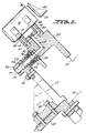
- manifold 52 remote from interface 50 extends into arcuate depression 54 of adjustable valve element 55 that is mounted by two bolts 56 to bracket 57. The latter is secured by two bolts 58 to bracket 66 which in turn is secured to stationary frame 101.
- Bolts 56 extend through short arcuate slots 59 in element 55 to permit limited adjustment of valving manifold 52, 55 relative to frame 101.
- a suction pump (not shown) is connected to manifold element 55 at threaded inlet 61 thereof.
- Reference numerals 62 indicate the apertures in movable valve ring 49 through which vacuum is applied to suction passages 48 in rim 99 of pocket wheel 12.
- the length of manifold 52 is such that the suction holding force acting to stabilize can 16 fully seated in pocket 17 is discontinued at the time there is initial engagement between pusher arm 42 and can 16, as arm 42 moves axially toward cradle 20.
- infeed chute 115 is constructed so that at the downstream end thereof cans 16 are moving downward as contrasted with downstream end 15a of chute 15 which curves slightly upward.
- Nozzle 117 directs airflow to the interior of chute 115 and in a downstream direction to impinge on cans 16 in chute 115 and urge them downstream.
- the most downstream can 16 in chute 115 contacts lead-in surface 37 the sidewall of this can is still engaged by the sidewall of the next upstream can in chute 115, which in turn has its sidewall engaged by the sidewall of the third most downstream can in chute 115.
- pocket wheel 12 typically has twenty-four equally spaced pockets 17 formed by arcs drawn about centers that are approximately 50cm from center 19 of wheel 12.
- the application of suction to each pocket 17 takes place from the point where a can 16 is initially fully seated in pocket 17 and is discontinued immediately prior to engagement of wiper blade or cam 42 with can 16. In all, suction is applied to each pocket 17 for approximately 16 to 30 degrees of rotation for pocket wheel 12.
Landscapes
- Chemical & Material Sciences (AREA)
- Inorganic Chemistry (AREA)
- Engineering & Computer Science (AREA)
- Materials Engineering (AREA)
- Organic Chemistry (AREA)
- Specific Conveyance Elements (AREA)
- Toys (AREA)
- Cosmetics (AREA)
Claims (14)
- Dispositif à haute vitesse pour la décoration d'objets cylindriques comprenant :
une pluralité de mandrins espacés sous un certain angle, montée sur une roue à mandrins en rotation ;
une roue à godets en rotation coaxiale avec la roue à mandrins et présentant une pluralité de godets espacés régulièrement sur sa périphérie pour coopérer avec la pluralité de mandrins ;
un premier moyen pour introduire dans les godets des objets cylindriques au moment où les godets décrivent un mouvement angulaire à travers une région de transfert et pour les orienter dans la direction axiale vers les mandrins afin de les charger tandis que les roues sont en rotation à pleine vitesse ;
un second moyen pour alimenter la roue à godets en objets cylindriques afin de les charger dans les godets dans une région de chargement située en amont de la région de transfert ;
caractérisé en ce que le dispositif présente un troisième moyen pour appliquer une force d'aspiration dans la direction radiale vers l'intérieur aux objets cylindriques lorsqu'ils ont été introduits dans les godets afin de stabiliser ces objets à l'intérieur des godets tandis qu'ils sont transportés vers la région de transfert par la roue à godets et jusqu'à ce que le premier moyen vienne en prise avec ces objets pour les transférer vers les mandrins. - Dispositif à haute vitesse selon la revendication 1, dans lequel le nombre de godets périphériques régulièrement espacés sur la roue rotative est égal à la pluralité des mandrins montés sur la roue à mandrins.
- Dispositif selon la revendication 1 ou 2, dans lequel la roue à godets porte sur sa périphérie une pluralité de surfaces d'entrée qui se prolongent en aval à partir d'un godet individuel et
chaque surface d'entrée est progressivement en retrait radial vers l'intérieur en s'approchant du godet dans lequel la surface d'entrée particulière oriente les objets cylindriques. - Dispositif selon l'une quelconque des revendications précédentes, dans lequel la force d'aspiration est appliquée par le troisième moyen à chaque godet au cours de la rotation de la roue à godets sur environ 15 à 30 degrés.
- Dispositif selon l'une quelconque des revendications précédentes, dans lequel l'application d'une force d'aspiration à un objet cylindrique est interrompue pendant que le premier moyen est en prise avec l'objet.
- Dispositif selon l'une quelconque des revendications précédentes, dans lequel chaque godet monte en se déplaçant de la région de chargement à la région de transfert.
- Dispositif selon l'une quelconque des revendications précédentes, dans lequel le second moyen comprend une goulotte de guidage ayant une extrémité aval dans la région de chargement, et
dans lequel le second moyen comprend également une section qui sollicite des objets cylindriques présents dans la goulotte vers son extrémité aval. - Dispositif selon la revendication 7, dans lequel la section du second moyen applique un flux d'air qui est orienté vers l'aval par rapport à la goulotte et qui frappe les parois latérales des objets cylindriques se déplaçant le long de la goulotte.
- Dispositif selon la revendication 7 ou 8, dans lequel la section du second moyen comprend une roue en étoile tournant en synchronisme avec la roue à godets ;
la roue en étoile étant fonctionnellement positionnée de manière à venir en prise avec des objets cylindriques se déplaçant vers l'aval à l'intérieur de la goulotte,
les objets cylindriques étant dégagés de la roue en étoile lorsqu'ils sont introduits dans les godets ;
avant d'atteindre la roue en étoile, des objets cylindriques adjacents présents dans la goulotte ont leur paroi latérale en prise ;
la roue en étoile comportant des godets périphériques qui reçoivent les objets cylindriques est prévue pour définir entre ces objets un espacement prédéterminé au moment où ils sont appliqués à la région de chargement. - Dispositif selon la revendication 9, dans lequel la section du second moyen applique également un flux d'air qui est dirigé vers l'aval par rapport à la goulotte et vient frapper les parois latérales d'objets cylindriques se déplaçant le long de la goulotte.
- Dispositif selon la revendication 9, dans lequel une force d'aspiration radiale orientée vers l'intérieur est appliquée à chaque godet de ladite roue en étoile dans des positions angulaires de cette dernière, et se trouve interrompue en un point se trouvant avant l'introduction complète d'un objet cylindrique dans un godet de ladite roue à godets.
- Dispositif selon l'une quelconque des revendications précédentes, dans lequel le premier moyen est constitué par un moyen de came fixe ;
les objets cylindriques tandis qu'ils sont déplacés à travers la région de transfert par la roue à godets ayant leurs extrémités éloignées des mandrins qui frottent en travers de l'élément de came installé pour orienter les objets cylindriques dans la direction axiale vers les mandrins. - Dispositif selon la revendication 12, dans lequel le moyen de came est allongé et en biais vers lesdits mandrins dans une direction vers l'aval.
- Dispositif selon l'une quelconque des revendications précédentes dans lequel les objets cylindriques sont des boîtes ayant un diamètre compris entre 5 et 10 cm.
Priority Applications (1)
| Application Number | Priority Date | Filing Date | Title |
|---|---|---|---|
| AT89304683T ATE98561T1 (de) | 1988-05-09 | 1989-05-09 | Hochgeschwindigkeits-dosendekorationsvorrichtun . |
Applications Claiming Priority (2)
| Application Number | Priority Date | Filing Date | Title |
|---|---|---|---|
| US07/191,693 US4921093A (en) | 1988-05-09 | 1988-05-09 | Infeed means for high speed continuous motion can decorator |
| US191693 | 1988-05-09 |
Publications (3)
| Publication Number | Publication Date |
|---|---|
| EP0341982A2 EP0341982A2 (fr) | 1989-11-15 |
| EP0341982A3 EP0341982A3 (en) | 1990-11-22 |
| EP0341982B1 true EP0341982B1 (fr) | 1993-12-15 |
Family
ID=22706555
Family Applications (1)
| Application Number | Title | Priority Date | Filing Date |
|---|---|---|---|
| EP89304683A Expired - Lifetime EP0341982B1 (fr) | 1988-05-09 | 1989-05-09 | Dispositif à haute vitesse pour la décoration de boîtes |
Country Status (7)
| Country | Link |
|---|---|
| US (1) | US4921093A (fr) |
| EP (1) | EP0341982B1 (fr) |
| JP (1) | JPH0256323A (fr) |
| AT (1) | ATE98561T1 (fr) |
| CA (1) | CA1310540C (fr) |
| DE (1) | DE68911369T2 (fr) |
| ES (1) | ES2046472T3 (fr) |
Families Citing this family (14)
| Publication number | Priority date | Publication date | Assignee | Title |
|---|---|---|---|---|
| US5337659A (en) * | 1993-02-22 | 1994-08-16 | Sequa Corporation | Apparatus and method utilizing continuous motion offset and direct printing techniques for decorating cylindrical containers |
| US5799574A (en) * | 1997-06-16 | 1998-09-01 | Sequa Corporation | Spindle disc for high speed can decorators |
| US7350315B2 (en) * | 2003-12-22 | 2008-04-01 | Lam Research Corporation | Edge wheel dry manifold |
| US7347899B2 (en) * | 2006-04-07 | 2008-03-25 | Day Benjamin F | Decorator temperature control system |
| US8418836B2 (en) | 2010-05-07 | 2013-04-16 | The Procter & Gamble Company | Universally adjustable star wheel |
| US8813950B2 (en) | 2010-05-07 | 2014-08-26 | The Procter & Gamble Company | Automated adjustment system for star wheel |
| US9475276B2 (en) | 2011-04-27 | 2016-10-25 | Stolle Machinery Company, Llc | Can decorator machine, ink station assembly therefor, and can decorating method employing same |
| US9169085B2 (en) * | 2012-12-06 | 2015-10-27 | Belvac Production Machinery, Inc. | Compliant vacuum transfer starwheel |
| US20230182159A1 (en) * | 2014-09-11 | 2023-06-15 | Kevin Gillest | Decorative Defect Re-Basecoating System for Cans and other Cylindrical Containers |
| FR3026097B1 (fr) * | 2014-09-19 | 2017-09-29 | Visio Nerf | Dispositif de transfert de pieces en defilement |
| FR3080319B1 (fr) | 2018-04-20 | 2022-01-07 | Sidel Participations | Procede de transport et dispositif de transport de type rotatif pour des preformes en matiere thermoplastique |
| PL3873741T3 (pl) | 2018-10-31 | 2025-11-17 | Crown Packaging Technology, Inc. | Zespół podawacza tuszu zawierający wałki oscylujące do urządzenia do dekorowania korpusów puszek |
| MX2021005328A (es) | 2018-11-09 | 2022-10-10 | Ball Corp | Un rodillo medidor para un ensamble de estación de tinta de un decorador y un método para decorar un contenedor con la decoración. |
| AU2024257748A1 (en) | 2023-04-17 | 2025-11-06 | Sandon Global Engraving Technology Limited | Liquid applicator sleeve and an applicator assembly including such a sleeve |
Family Cites Families (21)
| Publication number | Priority date | Publication date | Assignee | Title |
|---|---|---|---|---|
| US2500465A (en) * | 1945-08-27 | 1950-03-14 | Meyer Geo J Mfg Co | Filling machine drive |
| US3613571A (en) * | 1968-02-27 | 1971-10-19 | Brown Machine Co Of Michigan | Container printing machine and method of printing |
| US3563170A (en) * | 1968-04-16 | 1971-02-16 | Reynolds Metals Co | Machine for marking the exterior cylindrical surfaces of cans in a continous nonidexing manner |
| US3548745A (en) * | 1968-06-21 | 1970-12-22 | Sun Chemical Corp | Mandrel assembly for continuous can printing |
| US3586175A (en) * | 1968-11-15 | 1971-06-22 | Sun Chemical Corp | Transfer assembly for use with container printing machines |
| US3612313A (en) * | 1969-10-29 | 1971-10-12 | Continental Can Co | Rotary vacuum can holddown and method |
| US3766851A (en) * | 1971-11-15 | 1973-10-23 | Sun Chemical Corp | Continuous can printer and handling apparatus |
| US3976187A (en) * | 1972-04-07 | 1976-08-24 | Continental Can Company, Inc | Reciprocating pusher for transferring articles between conveyors |
| US3855967A (en) * | 1973-03-21 | 1974-12-24 | Sun Chemical Corp | Overvarnish unit for continuous-motion decorating apparatus |
| FR2230154A5 (fr) * | 1973-05-18 | 1974-12-13 | Decoufle Usines | |
| JPS536916B2 (fr) * | 1973-11-15 | 1978-03-13 | ||
| US4048917A (en) * | 1975-09-26 | 1977-09-20 | Sun Chemical Corporation | Continuous motion printing apparatus |
| US4138941A (en) * | 1975-10-06 | 1979-02-13 | Coors Container Company | Continuous gravity fed can printer and transfer apparatus |
| US4140053A (en) * | 1977-06-16 | 1979-02-20 | Sun Chemical Corporation | Mandrel mounting and trip mechanism for continuous motion decorator |
| US4458804A (en) * | 1977-08-12 | 1984-07-10 | Sun Chemical Corporation | Contour in-feed means for continuous motion can decorator |
| US4337719A (en) * | 1981-04-16 | 1982-07-06 | Van Dam Machine Corporation Of America | Mandrel support means for container decorating apparatus |
| JPS57178754A (en) * | 1981-04-25 | 1982-11-04 | Shin Nippon Koki Kk | Transfer unit for decorating machine of outer periphery of cylindrical article |
| JPS59113880A (ja) * | 1982-12-22 | 1984-06-30 | 日本たばこ産業株式会社 | 巻たばこ反転装置 |
| US4509555A (en) * | 1983-02-07 | 1985-04-09 | Adolph Coors Company | Disk transfer system |
| US4773326A (en) * | 1986-12-04 | 1988-09-27 | Adolph Coors Company | Printing machine with mandrel wheel skip-print verification and response |
| US4750420A (en) * | 1987-11-03 | 1988-06-14 | Adolph Coors Company | Rotatable cam for skip-print mandrel wheel assembly |
-
1988
- 1988-05-09 US US07/191,693 patent/US4921093A/en not_active Expired - Lifetime
-
1989
- 1989-05-08 CA CA000598951A patent/CA1310540C/fr not_active Expired - Lifetime
- 1989-05-09 JP JP1115960A patent/JPH0256323A/ja active Pending
- 1989-05-09 ES ES198989304683T patent/ES2046472T3/es not_active Expired - Lifetime
- 1989-05-09 AT AT89304683T patent/ATE98561T1/de not_active IP Right Cessation
- 1989-05-09 EP EP89304683A patent/EP0341982B1/fr not_active Expired - Lifetime
- 1989-05-09 DE DE89304683T patent/DE68911369T2/de not_active Expired - Fee Related
Also Published As
| Publication number | Publication date |
|---|---|
| JPH0256323A (ja) | 1990-02-26 |
| CA1310540C (fr) | 1992-11-24 |
| ATE98561T1 (de) | 1994-01-15 |
| ES2046472T3 (es) | 1994-02-01 |
| US4921093A (en) | 1990-05-01 |
| EP0341982A3 (en) | 1990-11-22 |
| DE68911369T2 (de) | 1994-04-14 |
| EP0341982A2 (fr) | 1989-11-15 |
| DE68911369D1 (de) | 1994-01-27 |
Similar Documents
| Publication | Publication Date | Title |
|---|---|---|
| EP0341982B1 (fr) | Dispositif à haute vitesse pour la décoration de boîtes | |
| US5231926A (en) | Apparatus and method for substantially reducing can spacing and speed to match chain pins | |
| KR20000010527A (ko) | 개량의 성형륜 장치 | |
| US4138941A (en) | Continuous gravity fed can printer and transfer apparatus | |
| HK1046889A1 (zh) | 罐传送旋转盘系统 | |
| WO1994005515A1 (fr) | Procede et appareil de decoration d'articles | |
| JPH0559008B2 (fr) | ||
| US4771879A (en) | Container transfer system | |
| CN111225799A (zh) | 容器装饰装置和方法 | |
| EP0314973A2 (fr) | Came rotative pour un ensemble de tambour d'impression avec mandrins escamotables | |
| US5183145A (en) | Apparatus and method for automatically positioning valve means controlling the application of pressurized air to mandrels on a rotating carrier | |
| US5111742A (en) | Mandrel trip subassembly for continuous motion can decorators | |
| US4458804A (en) | Contour in-feed means for continuous motion can decorator | |
| US6531018B1 (en) | Method and device for decorating containers | |
| US4587926A (en) | Bottom rim coater for intermittently operated container decorating apparatus | |
| CA1090840A (fr) | Dispositif d'alimentation tangentielle d'une machine a etiqueter des boites de conserve en continu | |
| EP0448245A1 (fr) | ProcÀ©dé et dispositif d'alimentation de gaz | |
| JPH0771967B2 (ja) | びんなどのラベル貼付機 | |
| US20220212463A1 (en) | Method and device for printing the respective lateral surface of hollow objects | |
| JPS6226315B2 (fr) | ||
| JPH0692264B2 (ja) | ガラス瓶の擦り傷コーティング装置 |
Legal Events
| Date | Code | Title | Description |
|---|---|---|---|
| PUAI | Public reference made under article 153(3) epc to a published international application that has entered the european phase |
Free format text: ORIGINAL CODE: 0009012 |
|
| AK | Designated contracting states |
Kind code of ref document: A2 Designated state(s): AT BE CH DE ES FR GB GR IT LI LU NL SE |
|
| PUAL | Search report despatched |
Free format text: ORIGINAL CODE: 0009013 |
|
| AK | Designated contracting states |
Kind code of ref document: A3 Designated state(s): AT BE CH DE ES FR GB GR IT LI LU NL SE |
|
| 17P | Request for examination filed |
Effective date: 19910503 |
|
| 17Q | First examination report despatched |
Effective date: 19930304 |
|
| ITF | It: translation for a ep patent filed | ||
| GRAA | (expected) grant |
Free format text: ORIGINAL CODE: 0009210 |
|
| AK | Designated contracting states |
Kind code of ref document: B1 Designated state(s): AT BE CH DE ES FR GB GR IT LI LU NL SE |
|
| PG25 | Lapsed in a contracting state [announced via postgrant information from national office to epo] |
Ref country code: LI Effective date: 19931215 Ref country code: CH Effective date: 19931215 |
|
| REF | Corresponds to: |
Ref document number: 98561 Country of ref document: AT Date of ref document: 19940115 Kind code of ref document: T |
|
| REF | Corresponds to: |
Ref document number: 68911369 Country of ref document: DE Date of ref document: 19940127 |
|
| REG | Reference to a national code |
Ref country code: ES Ref legal event code: FG2A Ref document number: 2046472 Country of ref document: ES Kind code of ref document: T3 |
|
| REG | Reference to a national code |
Ref country code: CH Ref legal event code: PL |
|
| ET | Fr: translation filed | ||
| PG25 | Lapsed in a contracting state [announced via postgrant information from national office to epo] |
Ref country code: LU Free format text: LAPSE BECAUSE OF NON-PAYMENT OF DUE FEES Effective date: 19940531 |
|
| REG | Reference to a national code |
Ref country code: GR Ref legal event code: FG4A Free format text: 3011072 |
|
| PLBE | No opposition filed within time limit |
Free format text: ORIGINAL CODE: 0009261 |
|
| STAA | Information on the status of an ep patent application or granted ep patent |
Free format text: STATUS: NO OPPOSITION FILED WITHIN TIME LIMIT |
|
| 26N | No opposition filed | ||
| EAL | Se: european patent in force in sweden |
Ref document number: 89304683.9 |
|
| PGFP | Annual fee paid to national office [announced via postgrant information from national office to epo] |
Ref country code: FR Payment date: 19950316 Year of fee payment: 7 |
|
| PGFP | Annual fee paid to national office [announced via postgrant information from national office to epo] |
Ref country code: SE Payment date: 19950321 Year of fee payment: 7 |
|
| PGFP | Annual fee paid to national office [announced via postgrant information from national office to epo] |
Ref country code: GB Payment date: 19950324 Year of fee payment: 7 |
|
| PGFP | Annual fee paid to national office [announced via postgrant information from national office to epo] |
Ref country code: BE Payment date: 19950328 Year of fee payment: 7 |
|
| PGFP | Annual fee paid to national office [announced via postgrant information from national office to epo] |
Ref country code: GR Payment date: 19950331 Year of fee payment: 7 |
|
| PGFP | Annual fee paid to national office [announced via postgrant information from national office to epo] |
Ref country code: AT Payment date: 19950404 Year of fee payment: 7 |
|
| PGFP | Annual fee paid to national office [announced via postgrant information from national office to epo] |
Ref country code: ES Payment date: 19950421 Year of fee payment: 7 |
|
| PGFP | Annual fee paid to national office [announced via postgrant information from national office to epo] |
Ref country code: NL Payment date: 19950531 Year of fee payment: 7 |
|
| PGFP | Annual fee paid to national office [announced via postgrant information from national office to epo] |
Ref country code: DE Payment date: 19950630 Year of fee payment: 7 |
|
| PG25 | Lapsed in a contracting state [announced via postgrant information from national office to epo] |
Ref country code: GB Effective date: 19960509 Ref country code: AT Effective date: 19960509 |
|
| PG25 | Lapsed in a contracting state [announced via postgrant information from national office to epo] |
Ref country code: SE Effective date: 19960510 Ref country code: ES Free format text: LAPSE BECAUSE OF NON-PAYMENT OF DUE FEES Effective date: 19960510 |
|
| PG25 | Lapsed in a contracting state [announced via postgrant information from national office to epo] |
Ref country code: BE Effective date: 19960531 |
|
| BERE | Be: lapsed |
Owner name: SEQUA CORP. Effective date: 19960531 |
|
| PG25 | Lapsed in a contracting state [announced via postgrant information from national office to epo] |
Ref country code: GR Free format text: THE PATENT HAS BEEN ANNULLED BY A DECISION OF A NATIONAL AUTHORITY Effective date: 19961130 |
|
| PG25 | Lapsed in a contracting state [announced via postgrant information from national office to epo] |
Ref country code: NL Effective date: 19961201 |
|
| REG | Reference to a national code |
Ref country code: GR Ref legal event code: MM2A Free format text: 3011072 |
|
| GBPC | Gb: european patent ceased through non-payment of renewal fee |
Effective date: 19960509 |
|
| PG25 | Lapsed in a contracting state [announced via postgrant information from national office to epo] |
Ref country code: FR Effective date: 19970131 |
|
| PG25 | Lapsed in a contracting state [announced via postgrant information from national office to epo] |
Ref country code: DE Effective date: 19970201 |
|
| EUG | Se: european patent has lapsed |
Ref document number: 89304683.9 |
|
| NLV4 | Nl: lapsed or anulled due to non-payment of the annual fee |
Effective date: 19961201 |
|
| REG | Reference to a national code |
Ref country code: FR Ref legal event code: ST |
|
| REG | Reference to a national code |
Ref country code: ES Ref legal event code: FD2A Effective date: 19990503 |
|
| PGFP | Annual fee paid to national office [announced via postgrant information from national office to epo] |
Ref country code: IT Payment date: 20060531 Year of fee payment: 18 |
|
| PG25 | Lapsed in a contracting state [announced via postgrant information from national office to epo] |
Ref country code: IT Free format text: LAPSE BECAUSE OF NON-PAYMENT OF DUE FEES Effective date: 20070509 |