EP0341982B1 - High speed can decorator - Google Patents
High speed can decorator Download PDFInfo
- Publication number
- EP0341982B1 EP0341982B1 EP89304683A EP89304683A EP0341982B1 EP 0341982 B1 EP0341982 B1 EP 0341982B1 EP 89304683 A EP89304683 A EP 89304683A EP 89304683 A EP89304683 A EP 89304683A EP 0341982 B1 EP0341982 B1 EP 0341982B1
- Authority
- EP
- European Patent Office
- Prior art keywords
- wheel
- cylindrical objects
- mandrels
- pockets
- Prior art date
- Legal status (The legal status is an assumption and is not a legal conclusion. Google has not performed a legal analysis and makes no representation as to the accuracy of the status listed.)
- Expired - Lifetime
Links
Images


Classifications
-
- B—PERFORMING OPERATIONS; TRANSPORTING
- B41—PRINTING; LINING MACHINES; TYPEWRITERS; STAMPS
- B41F—PRINTING MACHINES OR PRESSES
- B41F17/00—Printing apparatus or machines of special types or for particular purposes, not otherwise provided for
- B41F17/08—Printing apparatus or machines of special types or for particular purposes, not otherwise provided for for printing on filamentary or elongated articles, or on articles with cylindrical surfaces
- B41F17/14—Printing apparatus or machines of special types or for particular purposes, not otherwise provided for for printing on filamentary or elongated articles, or on articles with cylindrical surfaces on articles of finite length
- B41F17/20—Printing apparatus or machines of special types or for particular purposes, not otherwise provided for for printing on filamentary or elongated articles, or on articles with cylindrical surfaces on articles of finite length on articles of uniform cross-section, e.g. pencils, rulers, resistors
- B41F17/22—Printing apparatus or machines of special types or for particular purposes, not otherwise provided for for printing on filamentary or elongated articles, or on articles with cylindrical surfaces on articles of finite length on articles of uniform cross-section, e.g. pencils, rulers, resistors by rolling contact
-
- C—CHEMISTRY; METALLURGY
- C09—DYES; PAINTS; POLISHES; NATURAL RESINS; ADHESIVES; COMPOSITIONS NOT OTHERWISE PROVIDED FOR; APPLICATIONS OF MATERIALS NOT OTHERWISE PROVIDED FOR
- C09K—MATERIALS FOR MISCELLANEOUS APPLICATIONS, NOT PROVIDED FOR ELSEWHERE
- C09K21/00—Fireproofing materials
- C09K21/02—Inorganic materials
Definitions
- This invention relates to feeding apparatus for delivering cans from a feed chute to a mandrel wheel that is continuously rotating at very high speed, and is an improvement over the apparatus disclosed in U.S. Patent No. 4,458,804 issued July 10, 1984 to R. Williams and A. Rohr for Contour Infeed Means For Continuous Motion Can Decorator dramatically.
- Continuous motion high speed can decorating apparatus of the type illustrated in U.S. Patents Nos. 3,563,170, 3,766,851 and 3,976,187 utilize freely rotatable mandrels to carry cans while decorations are applied to the latter.
- the cans are loaded on the mandrels from a continuously rotating pocket wheel having curved seats or pockets along the periphery thereof to receive undecorated cans from a feed chute that extends from a supply source.
- a feed screw and star wheel combination interposed between the supply source and the pocket wheel to space the undecorated cans before they reach the pocket wheel.
- the instant invention provides quick acting means to stabilize each can as it reaches a fully seated position in a pocket wheel pocket.
- a can In this fully seated position a can is in precise axial alignment with a mandrel as soon as the can begins moving toward the mandrel.
- This quick acting means is a suction force that is applied in a timed sequence to a limited area of each pocket wheel pocket from the time of initial full seating of a can until this can moves axially toward the mandrel wheel.
- a primary object of the instant invention is to provide improved means for loading undecorated cans in the pockets of a continuously rotating pocket wheel for a continuous motion decorator.
- Another object is to provide loading means of this type which achieves improved operation at extremely high speeds.
- Still another object is to provide loading means of this type in which cans in the pocket wheel pockets are held by a suction force prior to being pushed to mandrel on a rotating wheel.
- a further object is to provide loading means of this type in which there is a relatively short angular travel for each pocket between a loading region where the pocket receives a can and a transfer regions where the can is removed from the pocket and loaded on an axially displaced mandrel.
- a high speed apparatus for decorating cylindrical objects which comprises, a plurality of angularly spaced mandrels mounted on a rotating mandrel wheel; a rotating pocket wheel coaxial with the mandrel wheel and having a plurality of equally spaced peripheral pockets for co-operating with the mandrels a first means for engaging in the pockets cylindrical objects as they pass angularly through a transfer region and directing them axially toward the mandrels for loading thereon while the wheels are rotating at full speed; a second means for delivering cylindrical objects to the pocket wheel for loading in the pockets at a loading region upstream of the transfer region characterised in that the apparatus has, a third means to apply a radially inward suction force to cylindrical objects after they are seated in the pockets to stabilize the objects therein while the objects are carried to the transfer region by the pocket wheel and until such objects are engaged by the first means for transfer to the mandrel.
- Fig. 1 illustrates continuous motion cylindrical container decorating apparatus of the general type descried in U.S Pat. No. 4,140,053, issued Feb. 20, 1979, to J.P. Skrypek et al. for a Mandrel Mounting and Trip Mechanism For Continuous Motion Decorator.
- the apparatus of Fig. 1 includes infeed conveyor chute 15 which receives cans 16 (Fig. 2) from a supply (not shown) and directs them to arcuate cradles or pockets 17 along the periphery of spaced parallel rings 13, 14 (Fig. 5) secured to rim portion 99 of pocket wheel 12.
- the latter is fixedly secured to carrier wheel 18 which in turn is keyed to continuously rotating horizontal drive shaft 19.
- Horizontal spindles or mandrels 20 are also mounted to wheel 18. Each spindle 20 is in spaced axial alignment with an individual pocket 17 in a short region extending downstream from infeed conveyor 15. Undecorated cans 16 are transferred from each pocket 17 to a mandrel 20 by wiping against stationary arm 42 (Fig. 2) which is angled inwardly in the downstream direction so as to function as a cam that drives can 16 horizontally (axially) toward mandrel 20. Suction applied through an axial passage 45 extending to end 46 of mandrel 20 which receives container 16 draws the latter to final seating position on mandrel 20.
- cans 16 While mounted on mandrels 20, cans 16 are decorated by being brought into engagement with continuously rotating image transfer mat or blanket 21 of the multicolor printing press indicated generally by reference numeral 22. Thereafter, and while still mounted on mandrels 20, each decorated can 16 is coated on the outside thereof with a protective film of varnish applied by engagement with the periphery of rotating applicator roll (not shown) in the overvarnish unit indicated generally by reference numeral 24, on shaft 23 thereof as a center. Cans 16 with decorations and a protective coating thereon are then transferred from mandrels 20 to suction cups (not shown) mounted along the periphery of rotating transfer wheel (not shown) of transfer unit 27, and rotates on shaft 28 thereof as a center. Cans 16 carried by transfer wheel 27 are deposited on generally horizontal pins 29 carried by chain-type output conveyor 30 which carries cans 16 through a curing oven (not shown).
- Each mandrel 20 must be loaded with a can 16 by the time mandrel 20 is in the proximity of sensors 63, 64 which detect whether the particular mandrel 20 contains a properly mounted can 16. If sensors 63, 64 detect that a mandrel 20 is unloaded or is not properly loaded, as this mandrel 20 passes through the decorating zone wherein printing blanket 21 normally engages cans 16 on mandrels 20, as explained in the aforesaid U.S. Pat. No. 4,140,053, this misloaded or unloaded mandrel 20 is moved to a "no-print" position wherein as this mandrel 20 moves through the decorating zone it will be spaced from the periphery of blanket 21.
- Figs. 1 through 5 as cans 16 reach the arcuate downstream end of chute 15 they are engaged by starwheel 35 which is driven to rotate in synchronism with pocket wheel 12.
- Equally spaced depressions 36 in the periphery of starwheel 35 act to space cans 16 from one another prior to engagement of the most downstream can 16 in chute 15 with lead-in surface 37 that extends downstream from each pocket 17.
- lead-in surface 37 proceeds toward pocket 17 upstream thereof, surface 37 moves toward axis 19 about which pocket wheel 12 rotates.
- An individual vacuum passage 71 extends radially inward from each depression 36 of starwheel 35 near the downstream end of depression 36. Suction is applied to each passage 71 when can 16 initially enters depression 36, the suction force serving to draw can 16 downstream in depression 36 and establish a uniform spacing between adjacent cans 16, 16 prior to engagement thereof with lead in surface 37.
- starwheel 35 establishes a center to center distance of 7.6cm between adjacent cans 16 and the center to center spacing between adjacent pockets 17 on pocket wheel 30.5 to 13.3 cm.
- a blower (not shown) drives air out of the lower open end of conduit 69 and directs this airflow against the sides of cans 16 in chute 15 to urge these cans downstream toward starwheel 35.
- manifold 52 remote from interface 50 extends into arcuate depression 54 of adjustable valve element 55 that is mounted by two bolts 56 to bracket 57. The latter is secured by two bolts 58 to bracket 66 which in turn is secured to stationary frame 101.
- Bolts 56 extend through short arcuate slots 59 in element 55 to permit limited adjustment of valving manifold 52, 55 relative to frame 101.
- a suction pump (not shown) is connected to manifold element 55 at threaded inlet 61 thereof.
- Reference numerals 62 indicate the apertures in movable valve ring 49 through which vacuum is applied to suction passages 48 in rim 99 of pocket wheel 12.
- the length of manifold 52 is such that the suction holding force acting to stabilize can 16 fully seated in pocket 17 is discontinued at the time there is initial engagement between pusher arm 42 and can 16, as arm 42 moves axially toward cradle 20.
- infeed chute 115 is constructed so that at the downstream end thereof cans 16 are moving downward as contrasted with downstream end 15a of chute 15 which curves slightly upward.
- Nozzle 117 directs airflow to the interior of chute 115 and in a downstream direction to impinge on cans 16 in chute 115 and urge them downstream.
- the most downstream can 16 in chute 115 contacts lead-in surface 37 the sidewall of this can is still engaged by the sidewall of the next upstream can in chute 115, which in turn has its sidewall engaged by the sidewall of the third most downstream can in chute 115.
- pocket wheel 12 typically has twenty-four equally spaced pockets 17 formed by arcs drawn about centers that are approximately 50cm from center 19 of wheel 12.
- the application of suction to each pocket 17 takes place from the point where a can 16 is initially fully seated in pocket 17 and is discontinued immediately prior to engagement of wiper blade or cam 42 with can 16. In all, suction is applied to each pocket 17 for approximately 16 to 30 degrees of rotation for pocket wheel 12.
Landscapes
- Chemical & Material Sciences (AREA)
- Inorganic Chemistry (AREA)
- Engineering & Computer Science (AREA)
- Materials Engineering (AREA)
- Organic Chemistry (AREA)
- Specific Conveyance Elements (AREA)
- Toys (AREA)
- Cosmetics (AREA)
Abstract
Description
- This invention relates to feeding apparatus for delivering cans from a feed chute to a mandrel wheel that is continuously rotating at very high speed, and is an improvement over the apparatus disclosed in U.S. Patent No. 4,458,804 issued July 10, 1984 to R. Williams and A. Rohr for Contour Infeed Means For Continuous Motion Can Decorator dramatically.
- Continuous motion high speed can decorating apparatus of the type illustrated in U.S. Patents Nos. 3,563,170, 3,766,851 and 3,976,187 utilize freely rotatable mandrels to carry cans while decorations are applied to the latter. The cans are loaded on the mandrels from a continuously rotating pocket wheel having curved seats or pockets along the periphery thereof to receive undecorated cans from a feed chute that extends from a supply source. Typically, there is a feed screw and star wheel combination interposed between the supply source and the pocket wheel to space the undecorated cans before they reach the pocket wheel.
- At high speeds, say greater than of 800 cans per minute, the likelihood of cans being damaged by the feed screw or being jammed thereat increases dramatically. In attempting to avoid this problem, the prior art replaced the lead screw by a star wheel having vacuum applied to the pockets thereof in a timed sequence. While this resulted in spacing the cans prior to placement thereof into the pockets of the pocket wheel this did not provide a complete solution at high speeds since only very limited time was available to fully seat each can before it was directed axially to be picked up by a mandrel. Thus, the prior art found it necessary to experiment with modifying the pocket wheel surfaces leading into the pockets thereof, as described in U.S Patent No. 4,458,804. Unfortunately, at very high can speeds, say greater than 1200 cans per minute, the time for a can to become seated in a pocket wheel pocket is so short that axial movement of the can toward a mandrel commenced before the can was fully stabilized in the pocket. This resulted in misloading cans and/or damaging same.
- To avoid the aforesaid problems encountered by the prior art in loading cans on mandrels of a continuous motion decorator operating at very high speed, the instant invention provides quick acting means to stabilize each can as it reaches a fully seated position in a pocket wheel pocket. In this fully seated position a can is in precise axial alignment with a mandrel as soon as the can begins moving toward the mandrel. This quick acting means is a suction force that is applied in a timed sequence to a limited area of each pocket wheel pocket from the time of initial full seating of a can until this can moves axially toward the mandrel wheel.
- Accordingly, a primary object of the instant invention is to provide improved means for loading undecorated cans in the pockets of a continuously rotating pocket wheel for a continuous motion decorator.
- Another object is to provide loading means of this type which achieves improved operation at extremely high speeds.
- Still another object is to provide loading means of this type in which cans in the pocket wheel pockets are held by a suction force prior to being pushed to mandrel on a rotating wheel.
- A further object is to provide loading means of this type in which there is a relatively short angular travel for each pocket between a loading region where the pocket receives a can and a transfer regions where the can is removed from the pocket and loaded on an axially displaced mandrel.
- These objects as well as other objects of this invention shall become readily apparent after¶ reading the following description of the accompanying drawings in which:
- Fig. 1 is a front elevation of continuous motion can decorating apparatus constructed in accordance with teachings of the instant invention.
- Fig. 2 is an enlarged fragmentary portion of Fig. 1 in the loading region where cans are received by the pocket wheel.
- Fig. 3 is another enlarged fragmentary portion of Fig. 1 which includes a side elevation of the valving means through which a suction stabilizing force provided by suction is applied to the pockets of the pocket wheel.
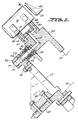
- Figs. 4 and 5 are enlarged fragmentary cross-sections taken through the respective lines 4-4 and 5-5 of Fig. 3 looking in the directions of the respective arrows 4-4 and 5-5.
- Fig. 6 is a view similar to Fig. 2 showing a modified construction at the downstream end of the feed chute that directs cans to the pocket wheel.
- According to the present invention a high speed apparatus for decorating cylindrical objects is provided which comprises,
a plurality of angularly spaced mandrels mounted on a rotating mandrel wheel;
a rotating pocket wheel coaxial with the mandrel wheel and having a plurality of equally spaced peripheral pockets for co-operating with the mandrels
a first means for engaging in the pockets cylindrical objects as they pass angularly through a transfer region and directing them axially toward the mandrels for loading thereon while the wheels are rotating at full speed;
a second means for delivering cylindrical objects to the pocket wheel for loading in the pockets at a loading region upstream of the transfer region characterised in that the apparatus has,
a third means to apply a radially inward suction force to cylindrical objects after they are seated in the pockets to stabilize the objects therein while the objects are carried to the transfer region by the pocket wheel and until such objects are engaged by the first means for transfer to the mandrel. - Now referring to the Figures and more particularly to Fig. 1 which illustrates continuous motion cylindrical container decorating apparatus of the general type descried in U.S Pat. No. 4,140,053, issued Feb. 20, 1979, to J.P. Skrypek et al. for a Mandrel Mounting and Trip Mechanism For Continuous Motion Decorator. Briefly, the apparatus of Fig. 1 includes infeed
conveyor chute 15 which receives cans 16 (Fig. 2) from a supply (not shown) and directs them to arcuate cradles orpockets 17 along the periphery of spacedparallel rings 13, 14 (Fig. 5) secured torim portion 99 ofpocket wheel 12. The latter is fixedly secured tocarrier wheel 18 which in turn is keyed to continuously rotatinghorizontal drive shaft 19. Horizontal spindles or mandrels 20 (Fig. 5) are also mounted towheel 18. Eachspindle 20 is in spaced axial alignment with anindividual pocket 17 in a short region extending downstream from infeedconveyor 15. Undecoratedcans 16 are transferred from eachpocket 17 to amandrel 20 by wiping against stationary arm 42 (Fig. 2) which is angled inwardly in the downstream direction so as to function as a cam that drives can 16 horizontally (axially) towardmandrel 20. Suction applied through anaxial passage 45 extending toend 46 ofmandrel 20 which receivescontainer 16 draws the latter to final seating position onmandrel 20. - While mounted on
mandrels 20,cans 16 are decorated by being brought into engagement with continuously rotating image transfer mat orblanket 21 of the multicolor printing press indicated generally byreference numeral 22. Thereafter, and while still mounted onmandrels 20, each decorated can 16 is coated on the outside thereof with a protective film of varnish applied by engagement with the periphery of rotating applicator roll (not shown) in the overvarnish unit indicated generally byreference numeral 24, onshaft 23 thereof as a center.Cans 16 with decorations and a protective coating thereon are then transferred frommandrels 20 to suction cups (not shown) mounted along the periphery of rotating transfer wheel (not shown) oftransfer unit 27, and rotates onshaft 28 thereof as a center.Cans 16 carried bytransfer wheel 27 are deposited on generallyhorizontal pins 29 carried by chain-type output conveyor 30 which carriescans 16 through a curing oven (not shown). - Each
mandrel 20 must be loaded with acan 16 by thetime mandrel 20 is in the proximity ofsensors particular mandrel 20 contains a properly mounted can 16. Ifsensors mandrel 20 is unloaded or is not properly loaded, as thismandrel 20 passes through the decorating zone whereinprinting blanket 21 normally engagescans 16 onmandrels 20, as explained in the aforesaid U.S. Pat. No. 4,140,053, this misloaded orunloaded mandrel 20 is moved to a "no-print" position wherein as thismandrel 20 moves through the decorating zone it will be spaced from the periphery ofblanket 21. - In the embodiment of Figs. 1 through 5, as
cans 16 reach the arcuate downstream end ofchute 15 they are engaged bystarwheel 35 which is driven to rotate in synchronism withpocket wheel 12. Equally spaceddepressions 36 in the periphery ofstarwheel 35 act tospace cans 16 from one another prior to engagement of the most downstream can 16 inchute 15 with lead-insurface 37 that extends downstream from eachpocket 17. In a manner known to the art, as lead-insurface 37 proceeds towardpocket 17 upstream thereof,surface 37 moves towardaxis 19 about whichpocket wheel 12 rotates. This serves to guide can 16 intopocket 17, and when can 16 is fully seated therein a suction stabilizing force is applied thereto, which force is applied until the closed end of can 16 is engaged byarm 42 which pushes can 16 to the near end ofmandrel 20 that is axially aligned with can 16 and from that point on suction applied throughpassage 45 draws can 16 axially until it is fully seated onmandrel 20. - An
individual vacuum passage 71 extends radially inward from eachdepression 36 ofstarwheel 35 near the downstream end ofdepression 36. Suction is applied to eachpassage 71 when can 16 initially entersdepression 36, the suction force serving to draw can 16 downstream indepression 36 and establish a uniform spacing betweenadjacent cans surface 37. In a typical construction, whencans 16 having a diameter of generally in the range of 5 to 10 cm with a typical can having a diameter of about 6.6 cm are being decorated,starwheel 35 establishes a center to center distance of 7.6cm betweenadjacent cans 16 and the center to center spacing betweenadjacent pockets 17 on pocket wheel 30.5 to 13.3 cm. A blower (not shown) drives air out of the lower open end ofconduit 69 and directs this airflow against the sides ofcans 16 inchute 15 to urge these cans downstream towardstarwheel 35. - When a
can 16 is initially seated in pocket 17 a suction holding force is applied thereto atdepression 46, there being adepression 46 in each of the aligned sections ofpocket 17 inrings depression 46 through an individual L-shaped passage 47 (Fig. 5). Bothpassages 47 communicate through single L-shaped passage 48 inpocket wheel rim 99 to the generally exposed valving surface ofmovable valve ring 49 that is secured torim 99.Ring 49 engagesstationary valve element 51 atinterface 50.Element 51 partially definesarcuate manifold 52 that is surrounded byseal 53 and is biased horizontally byspring 54 towardvalve ring 49. Horizontal movement ofelement 51 is stabilized by parallel pins 91 that project from element 51near opposite ends thereof. The side ofmanifold 52 remote frominterface 50 extends intoarcuate depression 54 ofadjustable valve element 55 that is mounted by twobolts 56 tobracket 57. The latter is secured by twobolts 58 tobracket 66 which in turn is secured tostationary frame 101.Bolts 56 extend through shortarcuate slots 59 inelement 55 to permit limited adjustment of valvingmanifold frame 101. A suction pump (not shown) is connected tomanifold element 55 at threadedinlet 61 thereof.Reference numerals 62 indicate the apertures inmovable valve ring 49 through which vacuum is applied tosuction passages 48 inrim 99 ofpocket wheel 12. The length ofmanifold 52 is such that the suction holding force acting to stabilize can 16 fully seated inpocket 17 is discontinued at the time there is initial engagement betweenpusher arm 42 and can 16, asarm 42 moves axially towardcradle 20. - In the embodiment of Fig. 6,
starwheel 35 of Figs 1 through 3 is eliminated andinfeed chute 115 is constructed so that at the downstreamend thereof cans 16 are moving downward as contrasted with downstream end 15a ofchute 15 which curves slightly upward. Nozzle 117 directs airflow to the interior ofchute 115 and in a downstream direction to impinge oncans 16 inchute 115 and urge them downstream. When the mostdownstream can 16 inchute 115 contacts lead-insurface 37 the sidewall of this can is still engaged by the sidewall of the next upstream can inchute 115, which in turn has its sidewall engaged by the sidewall of the third most downstream can inchute 115. Because of this, the force exerted by air exiting from nozzles 117 urges the most downstream can inchute 115 to remain against lead insurface 37 and be guided into a fully seated position withinpocket 17 at which time suction force applied atpocket depression 46 acts to stabilizecan 16 fully seated inpocket 17. A blower (not shown) directs air throughconduit 118 to exit therefrom at its lower end in the region wherecans 16 are loaded ontopocket wheel 12. The generally downward force provided by airflow from the lower end ofconduit 118 acts to stabilizecans 16 as they reach the downstream end of delivery chute 117 and are being loaded intopockets 17 ofpocket wheel 12. In Fig. 6 the next mostdownstream can 16 inchute 115 is shown spaced from the next downstream can 16 becausegate 133. The latter will remain closed at least until there is a significant head of cans upstream of thecan 16 that is being blocked by gate 113. - Typically the spacing between
center 19 ofpocket wheel 12 and the centers about which thearcs defining pockets 17 are drawn is approximately 50 to 102 cm. In a practical construction,pocket wheel 12 has twenty-four equally spacedpockets 17 formed by arcs drawn about centers that are approximately 50cm fromcenter 19 ofwheel 12. The application of suction to eachpocket 17 takes place from the point where acan 16 is initially fully seated inpocket 17 and is discontinued immediately prior to engagement of wiper blade orcam 42 withcan 16. In all, suction is applied to eachpocket 17 for approximately 16 to 30 degrees of rotation forpocket wheel 12. - Although a preferred embodiment of this invention has been described, many variations and modifications will now be apparent to those skilled in the art, and it is therefore preferred that the instant invention be limited not by the specific disclosure herein, but only by the appending claims.
Claims (14)
- A high speed apparatus for decorating cylindrical objects including:
a plurality of angularly spaced mandrels mounted on a rotating mandrel wheel;
a rotating pocket wheel coaxial with the mandrel wheel and having a plurality of equally spaced peripheral pockets for co-operating with the plurality of mandrels
a first means for engaging in the pockets cylindrical objects as they pass angularly through a transfer region and directing them axially toward the mandrels for loading thereon while the wheels are rotating at full speed;
a second means for delivering cylindrical objects to the pocket wheel for loading in the pockets at a loading region upstream of the transfer region characterised in that the apparatus has,
a third means to apply a radially inward suction force to cylindrical objecs after they are seated in the pockets to stabilize the objects therein while the objects are carried to the transfer region by the pocket wheel and until such objects are engaged by the first means for transfer to the mandrel. - The high speed apparatus according to claim 1 wherein the number of equally spacedperipheral pockets on the rotating wheel is equal to plurality of mandrels on the mandrel wheel
- Apparatus according to claim 1 or 2 in which the pocket wheel is provided along its perhiphery with a plurality of lead-in surfaces each extending downstream from an individual pocket and
each lead-in surface gradually retreating radially inward as it appproaches the pocket into which the particular lead-in surface directs cylindrical objects. - Apparatus according to any preceding claim in which the suction force is applied by the third means to each pocket for approximately 15 to 30° of rotation for the pocket wheel.
- Apparatus according to any preceding claim in which application of suction force to a cylindrical object is discontinued while it is engaged by the first means.
- Apparatus according to any preceding claim in which each pocket travels upward in moving from the loading region to the transfer region.
- Apparatus according to any preceding claim in which the second means includes a guide chute having a downstream end at the loading region and
the second means also includes a section which urges cylindrical objects in the chute toward the downstream end thereof. - Apparatus according to cliam 7 in which the section of the second means provides air flow that is directed downstream with respect to the chute and impinges upon sidewalls of cylindrical objects moving therealong.
- Apparatus according to claim 7 or 8 in which the section of the second means includes a starwheel rotating in synchronism with the pocket wheel;
the starwheel operatively positioned to engage cylindrical objects moving downstream in the chute;
the cylindrical objects being released from the starwheel upon being seated in the pockets;
prior to reaching the starwheel, adjacent cylindrical objects in the chute having their sidewalls in engagement;
the starwheel having peripheral pockets which receive the cylindrical objects to arrange the latter with a predetermined spacing as they are delivered to the loading region. - Apparatus according to 9 in which the section of the second means also provides air flow that is directed downstream with respect to the chute and impinges upon sidewalls of cylindrical objects moving therealong.
- Apparatus according to claim 9 in which a radially inward suction force is applied to each pocket of said starwheel for predetermined angular positions thereof, being discontinued at a point prior to full seating of a cylindrucal object in a pocket of said pocket wheel.
- Apparatus according to any preceding claim in which the first means comprises a stationary cam means;
the cylindrical objects while being carried through the transfer region by the pocket wheel having their ends remote from the mandrels wipe across the cam element which is disposed to direct the cylindrical objects axially toward the mandrels. - Apparatus according to claim 12 in which the cam means is elongated and angles toward said mandrels in a downstream direction.
- Apparatus according to any preceding claim in which the cylindrical objects are cans having a diameter in the range 5 to 10 cm.
Priority Applications (1)
| Application Number | Priority Date | Filing Date | Title |
|---|---|---|---|
| AT89304683T ATE98561T1 (en) | 1988-05-09 | 1989-05-09 | HIGH SPEED CAN DECORATION DEVICE . |
Applications Claiming Priority (2)
| Application Number | Priority Date | Filing Date | Title |
|---|---|---|---|
| US07/191,693 US4921093A (en) | 1988-05-09 | 1988-05-09 | Infeed means for high speed continuous motion can decorator |
| US191693 | 1988-05-09 |
Publications (3)
| Publication Number | Publication Date |
|---|---|
| EP0341982A2 EP0341982A2 (en) | 1989-11-15 |
| EP0341982A3 EP0341982A3 (en) | 1990-11-22 |
| EP0341982B1 true EP0341982B1 (en) | 1993-12-15 |
Family
ID=22706555
Family Applications (1)
| Application Number | Title | Priority Date | Filing Date |
|---|---|---|---|
| EP89304683A Expired - Lifetime EP0341982B1 (en) | 1988-05-09 | 1989-05-09 | High speed can decorator |
Country Status (7)
| Country | Link |
|---|---|
| US (1) | US4921093A (en) |
| EP (1) | EP0341982B1 (en) |
| JP (1) | JPH0256323A (en) |
| AT (1) | ATE98561T1 (en) |
| CA (1) | CA1310540C (en) |
| DE (1) | DE68911369T2 (en) |
| ES (1) | ES2046472T3 (en) |
Families Citing this family (14)
| Publication number | Priority date | Publication date | Assignee | Title |
|---|---|---|---|---|
| US5337659A (en) * | 1993-02-22 | 1994-08-16 | Sequa Corporation | Apparatus and method utilizing continuous motion offset and direct printing techniques for decorating cylindrical containers |
| US5799574A (en) * | 1997-06-16 | 1998-09-01 | Sequa Corporation | Spindle disc for high speed can decorators |
| US7350315B2 (en) * | 2003-12-22 | 2008-04-01 | Lam Research Corporation | Edge wheel dry manifold |
| US7347899B2 (en) * | 2006-04-07 | 2008-03-25 | Day Benjamin F | Decorator temperature control system |
| US8813950B2 (en) | 2010-05-07 | 2014-08-26 | The Procter & Gamble Company | Automated adjustment system for star wheel |
| US8418836B2 (en) * | 2010-05-07 | 2013-04-16 | The Procter & Gamble Company | Universally adjustable star wheel |
| US9475276B2 (en) | 2011-04-27 | 2016-10-25 | Stolle Machinery Company, Llc | Can decorator machine, ink station assembly therefor, and can decorating method employing same |
| US9169085B2 (en) * | 2012-12-06 | 2015-10-27 | Belvac Production Machinery, Inc. | Compliant vacuum transfer starwheel |
| US20230182159A1 (en) * | 2014-09-11 | 2023-06-15 | Kevin Gillest | Decorative Defect Re-Basecoating System for Cans and other Cylindrical Containers |
| FR3026097B1 (en) * | 2014-09-19 | 2017-09-29 | Visio Nerf | DEVICE FOR TRANSFERRING WORKPIECES |
| FR3080319B1 (en) | 2018-04-20 | 2022-01-07 | Sidel Participations | CONVEYING METHOD AND CONVEYING DEVICE OF ROTARY TYPE FOR PREFORMS MADE OF THERMOPLASTIC MATERIAL |
| BR112021008257A2 (en) | 2018-10-31 | 2021-08-03 | Crown Packaging Technology, Inc. | can body decorator having a mandrel pre-rotation set and feed improvements |
| EP3877183A4 (en) | 2018-11-09 | 2022-07-27 | Ball Corporation | A metering roller for an ink station assembly of a decorator and a method of decorating a container with the decoration |
| AU2024257748A1 (en) | 2023-04-17 | 2025-11-06 | Sandon Global Engraving Technology Limited | Liquid applicator sleeve and an applicator assembly including such a sleeve |
Family Cites Families (21)
| Publication number | Priority date | Publication date | Assignee | Title |
|---|---|---|---|---|
| US2500465A (en) * | 1945-08-27 | 1950-03-14 | Meyer Geo J Mfg Co | Filling machine drive |
| US3613571A (en) * | 1968-02-27 | 1971-10-19 | Brown Machine Co Of Michigan | Container printing machine and method of printing |
| US3563170A (en) * | 1968-04-16 | 1971-02-16 | Reynolds Metals Co | Machine for marking the exterior cylindrical surfaces of cans in a continous nonidexing manner |
| US3548745A (en) * | 1968-06-21 | 1970-12-22 | Sun Chemical Corp | Mandrel assembly for continuous can printing |
| US3586175A (en) * | 1968-11-15 | 1971-06-22 | Sun Chemical Corp | Transfer assembly for use with container printing machines |
| US3612313A (en) * | 1969-10-29 | 1971-10-12 | Continental Can Co | Rotary vacuum can holddown and method |
| US3766851A (en) * | 1971-11-15 | 1973-10-23 | Sun Chemical Corp | Continuous can printer and handling apparatus |
| US3976187A (en) * | 1972-04-07 | 1976-08-24 | Continental Can Company, Inc | Reciprocating pusher for transferring articles between conveyors |
| US3855967A (en) * | 1973-03-21 | 1974-12-24 | Sun Chemical Corp | Overvarnish unit for continuous-motion decorating apparatus |
| FR2230154A5 (en) * | 1973-05-18 | 1974-12-13 | Decoufle Usines | |
| JPS536916B2 (en) * | 1973-11-15 | 1978-03-13 | ||
| US4048917A (en) * | 1975-09-26 | 1977-09-20 | Sun Chemical Corporation | Continuous motion printing apparatus |
| US4138941A (en) * | 1975-10-06 | 1979-02-13 | Coors Container Company | Continuous gravity fed can printer and transfer apparatus |
| US4140053A (en) * | 1977-06-16 | 1979-02-20 | Sun Chemical Corporation | Mandrel mounting and trip mechanism for continuous motion decorator |
| US4458804A (en) * | 1977-08-12 | 1984-07-10 | Sun Chemical Corporation | Contour in-feed means for continuous motion can decorator |
| US4337719A (en) * | 1981-04-16 | 1982-07-06 | Van Dam Machine Corporation Of America | Mandrel support means for container decorating apparatus |
| JPS57178754A (en) * | 1981-04-25 | 1982-11-04 | Shin Nippon Koki Kk | Transfer unit for decorating machine of outer periphery of cylindrical article |
| JPS59113880A (en) * | 1982-12-22 | 1984-06-30 | 日本たばこ産業株式会社 | Cigarette reversal apparatus |
| US4509555A (en) * | 1983-02-07 | 1985-04-09 | Adolph Coors Company | Disk transfer system |
| US4773326A (en) * | 1986-12-04 | 1988-09-27 | Adolph Coors Company | Printing machine with mandrel wheel skip-print verification and response |
| US4750420A (en) * | 1987-11-03 | 1988-06-14 | Adolph Coors Company | Rotatable cam for skip-print mandrel wheel assembly |
-
1988
- 1988-05-09 US US07/191,693 patent/US4921093A/en not_active Expired - Lifetime
-
1989
- 1989-05-08 CA CA000598951A patent/CA1310540C/en not_active Expired - Lifetime
- 1989-05-09 ES ES198989304683T patent/ES2046472T3/en not_active Expired - Lifetime
- 1989-05-09 DE DE89304683T patent/DE68911369T2/en not_active Expired - Fee Related
- 1989-05-09 JP JP1115960A patent/JPH0256323A/en active Pending
- 1989-05-09 EP EP89304683A patent/EP0341982B1/en not_active Expired - Lifetime
- 1989-05-09 AT AT89304683T patent/ATE98561T1/en not_active IP Right Cessation
Also Published As
| Publication number | Publication date |
|---|---|
| ES2046472T3 (en) | 1994-02-01 |
| ATE98561T1 (en) | 1994-01-15 |
| DE68911369T2 (en) | 1994-04-14 |
| DE68911369D1 (en) | 1994-01-27 |
| US4921093A (en) | 1990-05-01 |
| JPH0256323A (en) | 1990-02-26 |
| EP0341982A2 (en) | 1989-11-15 |
| CA1310540C (en) | 1992-11-24 |
| EP0341982A3 (en) | 1990-11-22 |
Similar Documents
| Publication | Publication Date | Title |
|---|---|---|
| EP0341982B1 (en) | High speed can decorator | |
| US5231926A (en) | Apparatus and method for substantially reducing can spacing and speed to match chain pins | |
| CA2370395C (en) | Can transfer rotating plate system | |
| KR20000010527A (en) | Improved star wheel equipment | |
| US4138941A (en) | Continuous gravity fed can printer and transfer apparatus | |
| WO1994005515A1 (en) | Method and apparatus for decorating articles | |
| JPH0559008B2 (en) | ||
| CN111225799A (en) | Container decoration device and method | |
| US5183145A (en) | Apparatus and method for automatically positioning valve means controlling the application of pressurized air to mandrels on a rotating carrier | |
| US5111742A (en) | Mandrel trip subassembly for continuous motion can decorators | |
| US4458804A (en) | Contour in-feed means for continuous motion can decorator | |
| US4587926A (en) | Bottom rim coater for intermittently operated container decorating apparatus | |
| CA1090840A (en) | Contour in-feed means for continuous motion can decorator | |
| EP0448245A1 (en) | Gas supply apparatus and method | |
| JPH0771967B2 (en) | Labeling machine for bottles | |
| US20220212463A1 (en) | Method and device for printing the respective lateral surface of hollow objects | |
| CA1046096A (en) | Reciprocating-vacuum-rod chain to star wheel unloader for open cans | |
| JPS6226315B2 (en) | ||
| JPH0692264B2 (en) | Scratch coating device for glass bottles | |
| CZ336398A3 (en) | Machine for handling products and handling method |
Legal Events
| Date | Code | Title | Description |
|---|---|---|---|
| PUAI | Public reference made under article 153(3) epc to a published international application that has entered the european phase |
Free format text: ORIGINAL CODE: 0009012 |
|
| AK | Designated contracting states |
Kind code of ref document: A2 Designated state(s): AT BE CH DE ES FR GB GR IT LI LU NL SE |
|
| PUAL | Search report despatched |
Free format text: ORIGINAL CODE: 0009013 |
|
| AK | Designated contracting states |
Kind code of ref document: A3 Designated state(s): AT BE CH DE ES FR GB GR IT LI LU NL SE |
|
| 17P | Request for examination filed |
Effective date: 19910503 |
|
| 17Q | First examination report despatched |
Effective date: 19930304 |
|
| ITF | It: translation for a ep patent filed | ||
| GRAA | (expected) grant |
Free format text: ORIGINAL CODE: 0009210 |
|
| AK | Designated contracting states |
Kind code of ref document: B1 Designated state(s): AT BE CH DE ES FR GB GR IT LI LU NL SE |
|
| PG25 | Lapsed in a contracting state [announced via postgrant information from national office to epo] |
Ref country code: LI Effective date: 19931215 Ref country code: CH Effective date: 19931215 |
|
| REF | Corresponds to: |
Ref document number: 98561 Country of ref document: AT Date of ref document: 19940115 Kind code of ref document: T |
|
| REF | Corresponds to: |
Ref document number: 68911369 Country of ref document: DE Date of ref document: 19940127 |
|
| REG | Reference to a national code |
Ref country code: ES Ref legal event code: FG2A Ref document number: 2046472 Country of ref document: ES Kind code of ref document: T3 |
|
| REG | Reference to a national code |
Ref country code: CH Ref legal event code: PL |
|
| ET | Fr: translation filed | ||
| PG25 | Lapsed in a contracting state [announced via postgrant information from national office to epo] |
Ref country code: LU Free format text: LAPSE BECAUSE OF NON-PAYMENT OF DUE FEES Effective date: 19940531 |
|
| REG | Reference to a national code |
Ref country code: GR Ref legal event code: FG4A Free format text: 3011072 |
|
| PLBE | No opposition filed within time limit |
Free format text: ORIGINAL CODE: 0009261 |
|
| STAA | Information on the status of an ep patent application or granted ep patent |
Free format text: STATUS: NO OPPOSITION FILED WITHIN TIME LIMIT |
|
| 26N | No opposition filed | ||
| EAL | Se: european patent in force in sweden |
Ref document number: 89304683.9 |
|
| PGFP | Annual fee paid to national office [announced via postgrant information from national office to epo] |
Ref country code: FR Payment date: 19950316 Year of fee payment: 7 |
|
| PGFP | Annual fee paid to national office [announced via postgrant information from national office to epo] |
Ref country code: SE Payment date: 19950321 Year of fee payment: 7 |
|
| PGFP | Annual fee paid to national office [announced via postgrant information from national office to epo] |
Ref country code: GB Payment date: 19950324 Year of fee payment: 7 |
|
| PGFP | Annual fee paid to national office [announced via postgrant information from national office to epo] |
Ref country code: BE Payment date: 19950328 Year of fee payment: 7 |
|
| PGFP | Annual fee paid to national office [announced via postgrant information from national office to epo] |
Ref country code: GR Payment date: 19950331 Year of fee payment: 7 |
|
| PGFP | Annual fee paid to national office [announced via postgrant information from national office to epo] |
Ref country code: AT Payment date: 19950404 Year of fee payment: 7 |
|
| PGFP | Annual fee paid to national office [announced via postgrant information from national office to epo] |
Ref country code: ES Payment date: 19950421 Year of fee payment: 7 |
|
| PGFP | Annual fee paid to national office [announced via postgrant information from national office to epo] |
Ref country code: NL Payment date: 19950531 Year of fee payment: 7 |
|
| PGFP | Annual fee paid to national office [announced via postgrant information from national office to epo] |
Ref country code: DE Payment date: 19950630 Year of fee payment: 7 |
|
| PG25 | Lapsed in a contracting state [announced via postgrant information from national office to epo] |
Ref country code: GB Effective date: 19960509 Ref country code: AT Effective date: 19960509 |
|
| PG25 | Lapsed in a contracting state [announced via postgrant information from national office to epo] |
Ref country code: SE Effective date: 19960510 Ref country code: ES Free format text: LAPSE BECAUSE OF NON-PAYMENT OF DUE FEES Effective date: 19960510 |
|
| PG25 | Lapsed in a contracting state [announced via postgrant information from national office to epo] |
Ref country code: BE Effective date: 19960531 |
|
| BERE | Be: lapsed |
Owner name: SEQUA CORP. Effective date: 19960531 |
|
| PG25 | Lapsed in a contracting state [announced via postgrant information from national office to epo] |
Ref country code: GR Free format text: THE PATENT HAS BEEN ANNULLED BY A DECISION OF A NATIONAL AUTHORITY Effective date: 19961130 |
|
| PG25 | Lapsed in a contracting state [announced via postgrant information from national office to epo] |
Ref country code: NL Effective date: 19961201 |
|
| REG | Reference to a national code |
Ref country code: GR Ref legal event code: MM2A Free format text: 3011072 |
|
| GBPC | Gb: european patent ceased through non-payment of renewal fee |
Effective date: 19960509 |
|
| PG25 | Lapsed in a contracting state [announced via postgrant information from national office to epo] |
Ref country code: FR Effective date: 19970131 |
|
| PG25 | Lapsed in a contracting state [announced via postgrant information from national office to epo] |
Ref country code: DE Effective date: 19970201 |
|
| EUG | Se: european patent has lapsed |
Ref document number: 89304683.9 |
|
| NLV4 | Nl: lapsed or anulled due to non-payment of the annual fee |
Effective date: 19961201 |
|
| REG | Reference to a national code |
Ref country code: FR Ref legal event code: ST |
|
| REG | Reference to a national code |
Ref country code: ES Ref legal event code: FD2A Effective date: 19990503 |
|
| PGFP | Annual fee paid to national office [announced via postgrant information from national office to epo] |
Ref country code: IT Payment date: 20060531 Year of fee payment: 18 |
|
| PG25 | Lapsed in a contracting state [announced via postgrant information from national office to epo] |
Ref country code: IT Free format text: LAPSE BECAUSE OF NON-PAYMENT OF DUE FEES Effective date: 20070509 |