EP0341979A2 - Filière pour la fabrication d'un filament creux dans un filament composé creux contenant plusieurs éléments de séparation - Google Patents
Filière pour la fabrication d'un filament creux dans un filament composé creux contenant plusieurs éléments de séparation Download PDFInfo
- Publication number
- EP0341979A2 EP0341979A2 EP89304678A EP89304678A EP0341979A2 EP 0341979 A2 EP0341979 A2 EP 0341979A2 EP 89304678 A EP89304678 A EP 89304678A EP 89304678 A EP89304678 A EP 89304678A EP 0341979 A2 EP0341979 A2 EP 0341979A2
- Authority
- EP
- European Patent Office
- Prior art keywords
- passage
- filament
- spinneret
- hollow
- hollow filament
- Prior art date
- Legal status (The legal status is an assumption and is not a legal conclusion. Google has not performed a legal analysis and makes no representation as to the accuracy of the status listed.)
- Granted
Links
Images



Classifications
-
- B—PERFORMING OPERATIONS; TRANSPORTING
- B01—PHYSICAL OR CHEMICAL PROCESSES OR APPARATUS IN GENERAL
- B01D—SEPARATION
- B01D69/00—Semi-permeable membranes for separation processes or apparatus characterised by their form, structure or properties; Manufacturing processes specially adapted therefor
- B01D69/08—Hollow fibre membranes
-
- D—TEXTILES; PAPER
- D01—NATURAL OR MAN-MADE THREADS OR FIBRES; SPINNING
- D01D—MECHANICAL METHODS OR APPARATUS IN THE MANUFACTURE OF ARTIFICIAL FILAMENTS, THREADS, FIBRES, BRISTLES OR RIBBONS
- D01D5/00—Formation of filaments, threads, or the like
- D01D5/24—Formation of filaments, threads, or the like with a hollow structure; Spinnerette packs therefor
Definitions
- This invention relates to a hollow filament co-spun with a core within the hollow filament and spinnerets for co-spinning such filaments.
- Hollow-fiber membrane bioreactors are known and have utility in the production of materials from suspended or immobilized enzymes or cell cultures.
- Cells or enzymes are located within or outside of the hollow fibers with reaction substrates being supplied to the cells or enzymes while desired products are removed. Due to the compact proportions of a bioreactor, known manual methods of manufacturing such membranes are costly and time consuming, particularly when dual hollow filaments of extended length and fine diameter are involved.
- the inner surface of the outer filament and the peripheral surface of the inner filament can touch along their length to a significant degree. This contact can decrease the effective area of filament surface exposed to fluids or materials located in the space between the filament.
- Hollow-within-hollow fibers having means to keep the outer filament and the inner filament spaced from each other comprising spacing members projecting from the peripheral surface of the inner filament or from the inner surface of the outer filament and integral along the length thereof.
- One spinneret for the production of fibers of this proposal includes a plate having upper and lower surfaces connected by a capillary, the capillary comprising a segmented annular inner passage for extrusion of an inner hollow filament therethrough, an annular outer passage concentric with the inner passage for extrusion of an outer hollow filament therethrough, and means associated with the outer passage to direct polymer toward the inner passage during polymer extrusion.
- An alternate spinneret for the production of fibers of this proposal includes a plate having upper and lower surfaces connected by a capillary, the capillary comprising a segmented inner passage for extrusion of an inner hollow filament therethrough, an annular outer passage concentric with the inner passage for extrusion of an outer hollow filament therethrough, and means associated with the inner passage to direct polymer toward the outer passage during polymer extrusion.
- An inner passage of this alternate embodiment can comprise a plurality of segments, each segment comprising a first portion curved about the center of the capillary, a second portion extending in a straight line to the first portion, and a third portion extending from the second portion initially in a reverse curve direction with respect to the first portion.
- a plurality of support members spanning the outer passage, and means for venting a gas into the capillary to a location between the inner and outer passage.
- spinnerets used for co-spinning such filaments are of a one-piece design and do not suffer disadvantages of known prior art spinnerets which have been adapted to form hollow fibers.
- This invention minimizes contact between the separate inner and outer filament walls of hollow-within-hollow fibers. This contact can be minimized by incorporating into the hollow-within-hollow fiber structure means to keep the outer filament and the inner filament spaced from each other. These spacing means include spacing members projecting from the peripheral surface of the inner filament or from the inner surface of the outer filament and integral along the length thereof.
- One spinneret for the production of fibers of this proposal includes a plate having upper and lower surfaces connected by a capillary, the capillary comprising a segmented annular inner passage for extrusion of an inner hollow filament therethrough, an annular outer passage concentric with the inner passage for extrusion of an outer hollow filament therethrough, and means associated with the outer passage to direct polymer toward the inner passage during polymer extrusion.
- An alternate spinneret for the production of fibers of this proposal includes a plate having upper and lower surfaces connected by a capillary, the capillary comprising a segmented inner passage for extrusion of an inner hollow filament therethrough, an annular outer passage concentric with the inner passage for extrusion of an outer hollow filament therethrough, and means associated with the inner passage to direct polymer toward the outer passage during polymer extrusion.
- An inner passage of this alternate embodiment can comprise a plurality of segments, each segment comprising a first portion in the form of an arc curved with respect to the center of the capillary, a second portion extending in a straight line to the first portion, and a third portion extending from the second portion initially in a reverse curve direction with respect to the first portion.
- a plurality of support members spanning the other passage, and means for venting a gas into the capillary to a location between the inner and outer passage.
- spinnerets used for co-spinning such filaments are of a one-piece design and do not suffer disadvantages of known prior art spinnerets which have been adapted to form hollow fibers.
- spinneret 20 is adapted to be mounted in a filter pack for supplying one or more polymer compositions to be spun into the inner and outer filaments of a hollow-within-hollow fiber.
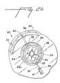
- the spinneret 20 is formed from plate 22 and is provided with a capillary 24, connecting its upper and lower surfaces 26, 28 respectively.
- Capillary 24 comprises an outer annular passage 30 concentric with segmented inner passage 32 and a venting passage 34 located between them.
- Support members 38 bridge annular passage 30 at angular locations to provide structural integrity to the spinneret.
- Bores 35, 36 are provided within plate 22 and pass through supports 38 to connect external openings 39, 40 to annular passage 34.
- Figs. 3 and 3A show recessed surface 26a in upper surface 26 and central bore 29.
- Figs. 2A and 7 show segmented inner passage 32 provided in lower plate section 28a through which polymer will be extruded to form the inner hollow filament of the fibers of this proposal.
- Inner passage 32 comprises three or more independent and curvate segments (shown as 32a, 32b, 32c, and 32d in Fig. 7) and separated by bridges 33.
- the segments comprise a first portion A in the form of an arc curved about the center C of the passage 32, a second portion K extending in a straight line from the first portion, and a third portion B extended from the second portion initially in a reverse curve direction with respect to the first portion.
- Passage 32 is constructed in a spinneret face by selecting a center point C for the passage and a center point D for each of the segments to be formed; creating first portions A having an inner edge radius F and outer edge radius G from center point C; forming reverse curve portion B as arcs having inner edge radius I and outer edge radius H from center point D; and connecting portions A and B with a second portion in the form of a straight line K.
- the second portion K will preferably be tangential on one edge to the inner arc of portion A and to the outer arc of third portion B and will also be tangential on its outer edge to the outer edge of first portion A and the inner edge of third portion B.
- the difference in length between G and F will be equal to the difference in length between H and I.
- the distance along line L from C to D will preferably be about equal to the length of H plus G where the length of G is preferably greater than or equal to the length of H.
- Segment B extends around center point D to a point defined with respect to line L. Segment B can be extended to meet line L or made shorter or longer which will then result in fibers formed therefrom having shorter or longer spacing members, respectively, from the suface thereof. If third portion B is continued past line L in an arc (e.g. 60 degrees), a hollow-shaped spacing member may be formed on the surface of a fiber.
- Bridges 33 separate the segments of passage 32 and provide structural integrity to the inner section of the passage.
- the length of bridges 33 are defined by the distance E between a line E′ extended parallel from the inside edge 70 of a segment of passage 32 and a second line E ⁇ drawn parallel to edge 70 and through segment corner 71. Typical values for the passage dimensions are given in the examples.
- Fig. 4 is an enlarged side view through line 4-4 of Fig. 3A to show vent bores 35, 36 passing through supports 38 to provide venting gas to chamber 37.
- Groove 41 is provided for ease of manufacture of bore 35 and to provide an unobstructed flow of fluid to opening 39.
- Fig. 5 shows support members 38 supporting chamber 37 and providing structural integrity to the spinneret at locations where bores 35, 36 are not present.
- Figs. 4 and 5 show lower surface segments 28a separated by passage 32; however, bridges 33 connect segments 28a at several locations on the lower surface of the spinneret as shown in Fig. 6 to complete the structural integrity of the spinneret.
- Fig. 14 shows an enlarged cross-section of a fiber formed by the spinneret described above.
- Inner filament 80 has been co-spun within outer filament 84.
- Spacing members 82 project from the peripheral surface 81 of inner filament 80 and are available to contact the inner surface 85 of outer filament 84 and maintain space 83.
- the size of the outer filament 84 relative to inner filament 80 will determine the extent of the contact of spacing members 82 with the inner surface 85 of the outer filament 84.
- a multiple feed distribution plate will provide polymer for the inner filament to bore 29 and polymer for the outer filament to recessed surface 26a.
- Polymer for the outer hollow filament will travel from recessed surface 26a to opening 30 where it will be extruded as a continuous hollow filament.
- polymer for the inner hollow filament will be supplied to bore 29 and extruded through passage 32.
- the freshly extruded inner hollow filament will initially be discontinuous along its perimeter due to bridges 33; however, coalescence of the polymer occurs immediately after extrusion to form a continuous perimeter hollow filament.
- Portions B of passage 32 will form spacing members 82 during extrusion.
- a gas for example, air
- passage 34 is supplied from passage 34 to maintain the space 83 between the inner and outer filament 80 and 84, repectively.
- Gas is supplied to passage 34 from chamber 37 which is fed from bores 35, 36 fed from openings 39, 40, respectively.
- a manifold (not shown) can be fit to the face of spinneret 20 to provide a positive gas pressure thereto for venting purposes.
- Figs. 8-13 illustrate an alternate embodiment of a spinneret of this proposal.
- Spinneret 43 is manufactured from plate 42 having lower and upper surfaces 48, 46 respectively.
- Capillary 44 extends through spinneret 43 and comprises an outer annular passage 50 having projections 51 directed inwardly therefrom and inner annular passage 52 interrupted by bridges 53. Vent openings 60 are located between outer passage 50 and inner passage 52 and communicates through bore 56 with openings 62 present in channel 55.
- Supports 58 bridge outer annular passage 50 to provide structural integrity to the spinneret. Bore 56 passes through bridges 58 to connect openings 62 and 60.
- Figs. 10 and 10A show recessed surface 46a in upper surface 46 and bore 49 communicating with segmented passage 52.
- Fig. 11 is an enlarged cross-sectional view through 11-11 of Fig. 9A and shows bore 56 passing through support 58 and in communication with channel 55 through opening 62 and with cylindrical bore 59 which terminates at opening 60 in the lower surface 48 of capillary 44.
- Fig. 11 also shows bridges 53 in communication with the spinneret lower face segment 48a which maintain the structural integrity of the spinneret.
- Figs. 9A and 12 show channels 51 in lower surface 48 extending from the inner surface of annular passage 50 and defined by beveled edge 51a tapering toward the annular passage 52.
- the channels terminate in straight portion 51b before reaching the annular passage 52.
- FIG. 15 shows filaments of this embodiment.
- An outer filament 90 contains spacing members 88 projecting inwardly from the inner surface 91 thereof and can contact the peripheral surface 87 of an inner hollow filament 86 to maintain a space 89 between the inner and outer filaments.
- polymer which will form the outer hollow filament is supplied through a suitable distribution manifold to recessed surface 46a where it enters annular passage 50 and is extruded as a continuous hollow filament from the spinneret lower surface. As this polymer reaches the lower surface of the spinneret, it additionally enters channels 51 where it forms spacing members 88 projecting from the inner surface 91 of the outer hollow filament 90. Simultaneously, a polymer which will form the inner hollow filament is supplied by a suitable distribution manifold to bore 49 where it is subsequently extruded at the lower surface of the spinneret through passage 52. Due to bridges 53, the newly extruded filament is discontinuous along its perimeter; however, it immediately coalesces after extrusion to form a continuous hollow filament.
- a gas for example, air
- Opening 60 is supplied from bore 56 which is fed from opening 62 in communication with channel 55.
- a manifold (not shown) can be fit to channel 55 to provide a positive gas pressure to opening 60 to maintain space 89 as the hollow-within-a-hollow fiber is formed.
- the spinneret used was a spinneret of the type shown in Figs. 1-7.
- the two polymers were melted separately in heated zone screw melters to a temperature of about 270°C and then extruded through the spinneret which was maintained at a temperature of about 270°C.
- the polymer forming the inner filament was metered at a rate of 2 g/min/passage and the polymer forming the outer filament was metered at a rate of 6 g/min/passage.
- the filaments were extruded from the spinneret, they were quenched with room temperature crossflow air and passed over a contact finish roll where a spin finish (a 10% solution of an alkylstearate ester lubricant emulsified with Aerosol® OT and Merpol® 1452) was applied to effect cohesion in the multi-filament bundle.
- the filaments were then brought together using convergence guides and wound-up onto a bobbin at 125 mpm.
- the filament was cut into thin sections and examined under light microscopy at a magnification of 250X and found to be a hollow-within-hollow fiber as shown in Fig. 14.
- the inner hollow filament 80 had support members 82 projecting therefrom in contact with the inner surface 85 of outer filament 84 maintaining a space 83 between the inner and outer filaments.
- the inner hollow filament was free from the outer filament and capable of being readily pulled out of the outer filament from one of its ends.
- the inner and outer filaments were melted separately in heated zone screw melters to a temperature of about 270°C and extruded through the spinneret which was maintained at about 270°C.
- the carbon black/polyethylene polymer forming the inner filament was metered at a rate of about 0.7 g/min/passage and the polymer forming the outer filament was metered at a rate of 4 g/min/passage.
- the filament was extruded from the spinneret, it was quenched with water and wound-up onto a bobbin at 50 mpm.
- the filament was crosssectioned and then examined using light microscopy at a magnification of 135X and found to be a hollow-within-hollow filament as shown in Fig. 15.
- the outer filament 90 had spacing members 88 projecting from the inner surface 91 thereof to contact the peripheral surface 87 of inner filament 86 and maintain space 89 between the inner and outer filaments.
Landscapes
- Engineering & Computer Science (AREA)
- Mechanical Engineering (AREA)
- Textile Engineering (AREA)
- Chemical & Material Sciences (AREA)
- Chemical Kinetics & Catalysis (AREA)
- Spinning Methods And Devices For Manufacturing Artificial Fibers (AREA)
- Separation Using Semi-Permeable Membranes (AREA)
- Artificial Filaments (AREA)
- Multicomponent Fibers (AREA)
Applications Claiming Priority (2)
| Application Number | Priority Date | Filing Date | Title |
|---|---|---|---|
| US193710 | 1988-05-10 | ||
| US07/193,710 US4941812A (en) | 1988-05-10 | 1988-05-10 | Spinneret for production of a hollow filament within a hollow filament composite fiber having spacing means |
Publications (3)
| Publication Number | Publication Date |
|---|---|
| EP0341979A2 true EP0341979A2 (fr) | 1989-11-15 |
| EP0341979A3 EP0341979A3 (en) | 1990-09-26 |
| EP0341979B1 EP0341979B1 (fr) | 1994-07-13 |
Family
ID=22714718
Family Applications (1)
| Application Number | Title | Priority Date | Filing Date |
|---|---|---|---|
| EP89304678A Expired - Lifetime EP0341979B1 (fr) | 1988-05-10 | 1989-05-09 | Filière pour la fabrication d'un filament creux dans un filament composé creux contenant plusieurs éléments de séparation |
Country Status (7)
| Country | Link |
|---|---|
| US (1) | US4941812A (fr) |
| EP (1) | EP0341979B1 (fr) |
| JP (1) | JPH0214009A (fr) |
| KR (1) | KR890017394A (fr) |
| CA (1) | CA1325871C (fr) |
| DE (1) | DE68916702T2 (fr) |
| RU (1) | RU2070624C1 (fr) |
Cited By (8)
| Publication number | Priority date | Publication date | Assignee | Title |
|---|---|---|---|---|
| EP0681040A1 (fr) * | 1994-05-06 | 1995-11-08 | SORIN BIOMEDICA CARDIO S.p.A. | Structure d'échange, par exemple pour équipement biomédical |
| SG80604A1 (en) * | 1998-10-02 | 2001-05-22 | Univ Singapore | Annular hollow fiber membranes for gas separation |
| US6805730B2 (en) * | 2002-01-29 | 2004-10-19 | Amersham Biosciences Membrane Separations Corp. | Convoluted surface hollow fiber membranes |
| US6899692B2 (en) * | 2001-10-17 | 2005-05-31 | Transvivo, Inc. | Plasmapheresis filter device and catheter assembly |
| US7267771B2 (en) | 2002-08-13 | 2007-09-11 | Transvivo, Inc. | Apparatus for therapeutic apheresis |
| US7481936B2 (en) | 2001-10-17 | 2009-01-27 | Transvivo Inc. | Method and apparatus for patient fluid management |
| FR2920786A1 (fr) * | 2007-09-07 | 2009-03-13 | Univ Claude Bernard Lyon | Fibres creuses, notamment multi membranaires, leur procede de preparation par filage et dispositif pour la mise en oeuvre dudit procede |
| US10293289B2 (en) | 2013-02-14 | 2019-05-21 | Nanopareil, Llc | Hybrid felts of electrospun nanofibers |
Families Citing this family (17)
| Publication number | Priority date | Publication date | Assignee | Title |
|---|---|---|---|---|
| US5125818A (en) * | 1991-02-05 | 1992-06-30 | Basf Corporation | Spinnerette for producing bi-component trilobal filaments |
| US5129812A (en) * | 1991-03-28 | 1992-07-14 | Basf Corporation | Multiple profile filaments from a single counterbore |
| US5540993A (en) * | 1993-02-16 | 1996-07-30 | E. I. Du Pont De Nemours And Company | Relating to fiber identification |
| US5540994A (en) * | 1993-02-16 | 1996-07-30 | E. I. Du Pont De Nemours And Company | Fiber identification |
| US5527611A (en) * | 1993-02-16 | 1996-06-18 | E. I. Du Pont De Nemours And Company | Relating to hollow fiber identification |
| US5484650A (en) * | 1993-02-16 | 1996-01-16 | E. I. Du Pont De Nemours And Company | Hollow fiber identification |
| AU678843B2 (en) * | 1993-08-10 | 1997-06-12 | W.L. Gore & Associates, Inc. | Cell encapsulating device |
| WO1997010807A1 (fr) * | 1995-09-22 | 1997-03-27 | Gore Hybrid Technologies, Inc. | Dispositif ameliore d'encapsulation de cellules |
| US6289928B1 (en) | 1998-12-04 | 2001-09-18 | Basf Corporation | Apparatus and method for direct injection of additives into a polymer melt stream |
| US6485650B1 (en) | 2000-08-28 | 2002-11-26 | Facilichem, Inc. | Liquid membrane separation of enantiomers |
| US20050106970A1 (en) * | 2000-09-01 | 2005-05-19 | Stanitis Gary E. | Melt processable perfluoropolymer forms |
| RU2261845C1 (ru) * | 2004-02-17 | 2005-10-10 | ООО "Каменный век" | Фильерный питатель для выработки волокна из горных пород |
| USD525271S1 (en) * | 2004-10-13 | 2006-07-18 | Dibella Michael | Sausage casing die |
| US10889915B2 (en) | 2018-01-31 | 2021-01-12 | Saudi Arabian Oil Company | Producing fibers using spinnerets |
| US11406941B2 (en) | 2020-02-14 | 2022-08-09 | Saudi Arabian Oil Company | Thin film composite hollow fiber membranes fabrication systems |
| US11253819B2 (en) | 2020-05-14 | 2022-02-22 | Saudi Arabian Oil Company | Production of thin film composite hollow fiber membranes |
| US12116326B2 (en) | 2021-11-22 | 2024-10-15 | Saudi Arabian Oil Company | Conversion of hydrogen sulfide and carbon dioxide into hydrocarbons using non-thermal plasma and a catalyst |
Family Cites Families (19)
| Publication number | Priority date | Publication date | Assignee | Title |
|---|---|---|---|---|
| US2879544A (en) * | 1955-04-05 | 1959-03-31 | Conte Soc | Device for the manufacture of pencils |
| US2999296A (en) * | 1957-03-25 | 1961-09-12 | Du Pont | Novel filaments and fabrics |
| US2988420A (en) * | 1959-02-16 | 1961-06-13 | Du Pont | Process for spinning polyacrylonitrile filament having low degree of crimp and high cimp reversibility |
| US2974613A (en) * | 1960-04-25 | 1961-03-14 | Maldarl And Sons Inc D | Macaroni die |
| US3585684A (en) * | 1966-12-23 | 1971-06-22 | Monsanto Co | Spinneret for making complex hollow filaments |
| NL6802563A (fr) * | 1967-02-25 | 1968-08-26 | ||
| JPS5521224A (en) * | 1978-07-31 | 1980-02-15 | Matsushita Electric Works Ltd | Extrusion die |
| JPS5590608A (en) * | 1978-12-27 | 1980-07-09 | Tanaka Kikinzoku Kogyo Kk | Manufacture of spinneret for hollow fiber |
| US4344907A (en) * | 1980-10-30 | 1982-08-17 | Mobil Oil Corporation | Method and apparatus providing uniform resin distribution in a coextruded product |
| DE3147709C2 (de) * | 1981-11-27 | 1984-12-06 | Mannesmann AG, 4000 Düsseldorf | Extruderkopf zum Ummanteln eines Stahlrohres |
| US4385886A (en) * | 1982-01-21 | 1983-05-31 | E. I. Du Pont De Nemours And Company | Spinneret plate |
| JPS60182948A (ja) * | 1984-02-29 | 1985-09-18 | 北浜 清 | 身体回動装置 |
| JPS6144022A (ja) * | 1984-08-08 | 1986-03-03 | Nippon Denso Co Ltd | 車両用窓の自動開閉装置 |
| JPS6146329A (ja) * | 1984-08-09 | 1986-03-06 | Fujitsu Ltd | 穴抜き剪断加工におけるクリアランス設定方法 |
| JPH0680206B2 (ja) * | 1985-03-01 | 1994-10-12 | ダイセル化学工業株式会社 | 多重中空糸紡糸用口金 |
| JPH0733602B2 (ja) * | 1985-03-22 | 1995-04-12 | ダイセル化学工業株式会社 | 多重管型中空糸 |
| US4743189A (en) * | 1986-06-27 | 1988-05-10 | E. I. Du Pont De Nemours And Company | Spinneret for a co-spun filament within a hollow filament |
| US4850847A (en) * | 1988-05-10 | 1989-07-25 | E. I. Du Pont De Nemours And Company | Spinneret for hollow fibers having curved spacing members projecting therefrom |
| US4836763A (en) * | 1988-07-29 | 1989-06-06 | E. I. Dupont De Nemours And Company | Seven hole spinneret |
-
1988
- 1988-05-10 US US07/193,710 patent/US4941812A/en not_active Expired - Lifetime
-
1989
- 1989-05-03 CA CA000598614A patent/CA1325871C/fr not_active Expired - Fee Related
- 1989-05-09 KR KR1019890006154A patent/KR890017394A/ko not_active Ceased
- 1989-05-09 EP EP89304678A patent/EP0341979B1/fr not_active Expired - Lifetime
- 1989-05-09 DE DE68916702T patent/DE68916702T2/de not_active Expired - Fee Related
- 1989-05-10 RU SU894614059A patent/RU2070624C1/ru active
- 1989-05-10 JP JP1115223A patent/JPH0214009A/ja active Pending
Cited By (11)
| Publication number | Priority date | Publication date | Assignee | Title |
|---|---|---|---|---|
| EP0681040A1 (fr) * | 1994-05-06 | 1995-11-08 | SORIN BIOMEDICA CARDIO S.p.A. | Structure d'échange, par exemple pour équipement biomédical |
| US5762870A (en) * | 1994-05-06 | 1998-06-09 | Sorin Biomedica Cardio S.P.A. | Exchange structure for biomedical equipment |
| SG80604A1 (en) * | 1998-10-02 | 2001-05-22 | Univ Singapore | Annular hollow fiber membranes for gas separation |
| US6899692B2 (en) * | 2001-10-17 | 2005-05-31 | Transvivo, Inc. | Plasmapheresis filter device and catheter assembly |
| US7481936B2 (en) | 2001-10-17 | 2009-01-27 | Transvivo Inc. | Method and apparatus for patient fluid management |
| US6805730B2 (en) * | 2002-01-29 | 2004-10-19 | Amersham Biosciences Membrane Separations Corp. | Convoluted surface hollow fiber membranes |
| US7267771B2 (en) | 2002-08-13 | 2007-09-11 | Transvivo, Inc. | Apparatus for therapeutic apheresis |
| FR2920786A1 (fr) * | 2007-09-07 | 2009-03-13 | Univ Claude Bernard Lyon | Fibres creuses, notamment multi membranaires, leur procede de preparation par filage et dispositif pour la mise en oeuvre dudit procede |
| WO2009044053A3 (fr) * | 2007-09-07 | 2009-08-27 | Universite Claude Bernard Lyon I | Fibres creuses, notamment multi membranaires, leur procede de preparation par filage et dispositif pour la mise en oeuvre dudit procede |
| US10293289B2 (en) | 2013-02-14 | 2019-05-21 | Nanopareil, Llc | Hybrid felts of electrospun nanofibers |
| USRE49773E1 (en) | 2013-02-14 | 2024-01-02 | Nanopareil, Llc | Hybrid felts of electrospun nanofibers |
Also Published As
| Publication number | Publication date |
|---|---|
| CA1325871C (fr) | 1994-01-11 |
| EP0341979B1 (fr) | 1994-07-13 |
| DE68916702D1 (de) | 1994-08-18 |
| US4941812A (en) | 1990-07-17 |
| JPH0214009A (ja) | 1990-01-18 |
| DE68916702T2 (de) | 1995-02-16 |
| EP0341979A3 (en) | 1990-09-26 |
| RU2070624C1 (ru) | 1996-12-20 |
| KR890017394A (ko) | 1989-12-16 |
Similar Documents
| Publication | Publication Date | Title |
|---|---|---|
| EP0341979B1 (fr) | Filière pour la fabrication d'un filament creux dans un filament composé creux contenant plusieurs éléments de séparation | |
| US4743189A (en) | Spinneret for a co-spun filament within a hollow filament | |
| US4861661A (en) | Co-spun filament within a hollow filament and spinneret for production thereof | |
| US4956237A (en) | Hollow fibers having curved members projecting therefor | |
| US5505889A (en) | Method of spinning bicomponent filaments | |
| EP0227832B1 (fr) | Fibre composite creuse et son procede de fabrication | |
| EP0058572B1 (fr) | Filière pour la fabrication de fibres composites | |
| KR100247265B1 (ko) | 복합 용융 취입 방사용 방사구금 장치 | |
| EP0646663B1 (fr) | Filière pour fusian-soufflage | |
| US4990297A (en) | Apparatus and method for cooling and conditioning melt-spun material | |
| US6881047B2 (en) | Process and apparatus for improved conditioning of melt-spun material | |
| US4756679A (en) | Apparatus for cooling and conditioning melt-spun material | |
| EP1402090B1 (fr) | Procede et appareil permettant de fabriquer des filaments a plusieurs couches et a plusieurs composants | |
| EP1285109B1 (fr) | Ensemble grille concu pour produire des fibres a deux composantes dans un appareil de fusion-soufflage | |
| US4229154A (en) | Spinneret for the production of hollow filaments | |
| NZ227626A (en) | Spinneret for production of filament containing voids | |
| CN209873195U (zh) | 全消光中空异形出口喷丝板 | |
| JP3546635B2 (ja) | 芯鞘複合繊維紡糸用口金板及び口金装置 | |
| JP2568314B2 (ja) | フィラメント紡糸口金装置 | |
| CN217997427U (zh) | 一种中空齿轮截面纤维喷丝板 | |
| CN216738650U (zh) | 一种月亮型中空纤维喷丝板 | |
| CA2067672A1 (fr) | Methode et appareil de filage pour filaments bi-element et produits ainsi obtenus | |
| JPH02307905A (ja) | 複合紡糸口金 | |
| JPS6212629A (ja) | ガラス繊維の製造装置 | |
| JPH0224772B2 (fr) |
Legal Events
| Date | Code | Title | Description |
|---|---|---|---|
| PUAI | Public reference made under article 153(3) epc to a published international application that has entered the european phase |
Free format text: ORIGINAL CODE: 0009012 |
|
| AK | Designated contracting states |
Kind code of ref document: A2 Designated state(s): DE FR GB SE |
|
| PUAL | Search report despatched |
Free format text: ORIGINAL CODE: 0009013 |
|
| AK | Designated contracting states |
Kind code of ref document: A3 Designated state(s): DE FR GB SE |
|
| 17P | Request for examination filed |
Effective date: 19901220 |
|
| 17Q | First examination report despatched |
Effective date: 19920907 |
|
| GRAA | (expected) grant |
Free format text: ORIGINAL CODE: 0009210 |
|
| AK | Designated contracting states |
Kind code of ref document: B1 Designated state(s): DE FR GB SE |
|
| REF | Corresponds to: |
Ref document number: 68916702 Country of ref document: DE Date of ref document: 19940818 |
|
| ET | Fr: translation filed | ||
| PG25 | Lapsed in a contracting state [announced via postgrant information from national office to epo] |
Ref country code: SE Effective date: 19941013 |
|
| PLBE | No opposition filed within time limit |
Free format text: ORIGINAL CODE: 0009261 |
|
| STAA | Information on the status of an ep patent application or granted ep patent |
Free format text: STATUS: NO OPPOSITION FILED WITHIN TIME LIMIT |
|
| 26N | No opposition filed | ||
| REG | Reference to a national code |
Ref country code: GB Ref legal event code: IF02 |
|
| REG | Reference to a national code |
Ref country code: GB Ref legal event code: 732E |
|
| REG | Reference to a national code |
Ref country code: GB Ref legal event code: 732E |
|
| PGFP | Annual fee paid to national office [announced via postgrant information from national office to epo] |
Ref country code: GB Payment date: 20060503 Year of fee payment: 18 |
|
| PGFP | Annual fee paid to national office [announced via postgrant information from national office to epo] |
Ref country code: DE Payment date: 20060508 Year of fee payment: 18 |
|
| PGFP | Annual fee paid to national office [announced via postgrant information from national office to epo] |
Ref country code: FR Payment date: 20060515 Year of fee payment: 18 |
|
| GBPC | Gb: european patent ceased through non-payment of renewal fee |
Effective date: 20070509 |
|
| REG | Reference to a national code |
Ref country code: FR Ref legal event code: ST Effective date: 20080131 |
|
| PG25 | Lapsed in a contracting state [announced via postgrant information from national office to epo] |
Ref country code: DE Free format text: LAPSE BECAUSE OF NON-PAYMENT OF DUE FEES Effective date: 20071201 |
|
| PG25 | Lapsed in a contracting state [announced via postgrant information from national office to epo] |
Ref country code: GB Free format text: LAPSE BECAUSE OF NON-PAYMENT OF DUE FEES Effective date: 20070509 |
|
| PG25 | Lapsed in a contracting state [announced via postgrant information from national office to epo] |
Ref country code: FR Free format text: LAPSE BECAUSE OF NON-PAYMENT OF DUE FEES Effective date: 20070531 |