EP0341861A2 - Zweidraht-Strom-Druckwandler mit Energiespeicherung - Google Patents
Zweidraht-Strom-Druckwandler mit Energiespeicherung Download PDFInfo
- Publication number
- EP0341861A2 EP0341861A2 EP89304182A EP89304182A EP0341861A2 EP 0341861 A2 EP0341861 A2 EP 0341861A2 EP 89304182 A EP89304182 A EP 89304182A EP 89304182 A EP89304182 A EP 89304182A EP 0341861 A2 EP0341861 A2 EP 0341861A2
- Authority
- EP
- European Patent Office
- Prior art keywords
- pressure
- valves
- regulator
- valve
- electrical
- Prior art date
- Legal status (The legal status is an assumption and is not a legal conclusion. Google has not performed a legal analysis and makes no representation as to the accuracy of the status listed.)
- Granted
Links
Images


Classifications
-
- G—PHYSICS
- G05—CONTROLLING; REGULATING
- G05D—SYSTEMS FOR CONTROLLING OR REGULATING NON-ELECTRIC VARIABLES
- G05D16/00—Control of fluid pressure
- G05D16/04—Control of fluid pressure without auxiliary power
- G05D16/06—Control of fluid pressure without auxiliary power the sensing element being a flexible membrane, yielding to pressure, e.g. diaphragm, bellows, capsule
- G05D16/063—Control of fluid pressure without auxiliary power the sensing element being a flexible membrane, yielding to pressure, e.g. diaphragm, bellows, capsule the sensing element being a membrane
- G05D16/0644—Control of fluid pressure without auxiliary power the sensing element being a flexible membrane, yielding to pressure, e.g. diaphragm, bellows, capsule the sensing element being a membrane the membrane acting directly on the obturator
- G05D16/0663—Control of fluid pressure without auxiliary power the sensing element being a flexible membrane, yielding to pressure, e.g. diaphragm, bellows, capsule the sensing element being a membrane the membrane acting directly on the obturator using a spring-loaded membrane with a spring-loaded slideable obturator
-
- G—PHYSICS
- G05—CONTROLLING; REGULATING
- G05D—SYSTEMS FOR CONTROLLING OR REGULATING NON-ELECTRIC VARIABLES
- G05D16/00—Control of fluid pressure
- G05D16/20—Control of fluid pressure characterised by the use of electric means
- G05D16/2093—Control of fluid pressure characterised by the use of electric means with combination of electric and non-electric auxiliary power
- G05D16/2095—Control of fluid pressure characterised by the use of electric means with combination of electric and non-electric auxiliary power using membranes within the main valve
-
- Y—GENERAL TAGGING OF NEW TECHNOLOGICAL DEVELOPMENTS; GENERAL TAGGING OF CROSS-SECTIONAL TECHNOLOGIES SPANNING OVER SEVERAL SECTIONS OF THE IPC; TECHNICAL SUBJECTS COVERED BY FORMER USPC CROSS-REFERENCE ART COLLECTIONS [XRACs] AND DIGESTS
- Y10—TECHNICAL SUBJECTS COVERED BY FORMER USPC
- Y10T—TECHNICAL SUBJECTS COVERED BY FORMER US CLASSIFICATION
- Y10T137/00—Fluid handling
- Y10T137/2496—Self-proportioning or correlating systems
- Y10T137/2559—Self-controlled branched flow systems
- Y10T137/2574—Bypass or relief controlled by main line fluid condition
- Y10T137/2605—Pressure responsive
- Y10T137/2607—With pressure reducing inlet valve
- Y10T137/261—Relief port through common sensing means
-
- Y—GENERAL TAGGING OF NEW TECHNOLOGICAL DEVELOPMENTS; GENERAL TAGGING OF CROSS-SECTIONAL TECHNOLOGIES SPANNING OVER SEVERAL SECTIONS OF THE IPC; TECHNICAL SUBJECTS COVERED BY FORMER USPC CROSS-REFERENCE ART COLLECTIONS [XRACs] AND DIGESTS
- Y10—TECHNICAL SUBJECTS COVERED BY FORMER USPC
- Y10T—TECHNICAL SUBJECTS COVERED BY FORMER US CLASSIFICATION
- Y10T137/00—Fluid handling
- Y10T137/7722—Line condition change responsive valves
- Y10T137/7758—Pilot or servo controlled
- Y10T137/7761—Electrically actuated valve
Definitions
- This invention relates to electro-pneumatic regulators and has particular reference to such regulators commonly referred to as I/P ("I to P") regulators.
- I/P regulators are used to control pneumatic pressure - usually of compressed air-in response to the electrical output of an electronic source.
- the common industry standard for the electronic source is that the current should vary in the range 4-20 mA with 4 mA corresponding to minimum pressure and 20 mA to maximum pressure.
- Electro-pneumatic regulators may either fail to zero when the current is cut off, or may fail to a freeze condition or to another pressure predetermined by the user.
- a fail to zero regulator the absence of current results in the pressure on the output line falling to a minimum.
- a fail-freeze regulator the sudden absence of current results in the pressure in the output line being maintained at the level obtaining immediately prior to the current failure. This is of advantage where the power is deliberately cut off when no pressure changes are required.
- a fail to a user predetermined pressure involves a pre-programmed device which either causes the device to fail freeze or to fail to any other predetermined pressure, such as fail to maximum or fail to a given pressure.
- Two-wire I/P regulators ie regulators which work off the electrical signal produced by the electronic apparatus, are known in which the electrical power operates an electromagnet to balance pneumatic pressure so as to regulate pressure.
- Such two-wire devices are fail to zero and a typical example is the Watson Smith I/P Converter Type 100, available from Watson Smith Limited, of Cross Chancellor Street, Leeds, England.
- Watson Smith I/P Converters are very accurate, they are somewhat fragile and difficult to make and they fail to zero, and the user cannot determine what happens to the pressure when they fail.
- An alternative form of electro-pneumatic regulator is an electronic device which controls the flow of air into the control chamber of a pressure regulator by means of low power solenoid valves. Such regulators require, however, a supplementary power source to permit them to operate. Such regulators as the Watson Smith Type 400 Series are also available from Watson Smith Limited.
- the 400 Series although it is fail-freeze, is not capable of operating solely on the power available from the electronic signal source, and requires a supplementary power source.
- Electro-pneumatic converters have also been proposed which fail-freeze and which appear to operate by the use of two wires only.
- Such devices are motorised devices in which an electric motor controls the position of the valve and the motor is driven by the power supplied from an electrical source. These devices need the external power source to operate the motor, namely a common return and an open and close wire for an AC motor or if a DC motor is used the device requires only two wires.
- DC motors do not operate from the electronic power source directly, but utilise an external power source which is controlled by the controller.
- Such systems are also not I/P converters in that the position of the valve is determined by the duration of operation of the motor rather than directly from the value of the current supplied by the electronic controller.
- a two-wire I/P converter as used herein therefore means an electro-pneumatic converter capable of regulating pressure of a fluid in response to variation in current from an electronic control circuit directly, without the use of supplementary power utilising an electrical current in the range 4-20 mA.
- I/P regulators have been available commercially capable of operating directly from the electronic signal source without an auxiliary electrical power supply. Although I/P regulators which have a slow decay so as to fail slowly to zero have been proposed in UK Patent Specification No 1 185 709.
- US patent 4509547 describes the use of a DC motor, a pressure regulator in which feed back is provided from the outlet pressure by means of a pressure transducer.
- UK specification 2123184 and 2128372 describes fail fix servo valves.
- UK patent specification 21243974 describes a system for linearising of the compressor prezo resistive transducer.
- UK patent specification 1214 describes a fail freeze flapper valve driven by a motor.
- PCT application 84/01445 describes a device in which the control signal of the reverse feedback are sent over the same pair of wires.
- an I/P converter which on removal of the signal current fails to a pressure predetermined by the user.
- a pressure may be the then current pressure or some predetermined pressure.
- the present invention also provides a fail to a user predetermined pressure two-wire electrically controlled fluid pressure regulator capable of operation with full-range control on an electrical current input in the range 4-20 mA to produce a proportionate pressure output in which the regulator includes a control volume whose pressure is variable in response to the electrical signal, and whose pressure controls the output pressure of a regulator in a manner known per se, there being provided normally closed inlet and outlet valves, the pressure in the control volume being increased by opening an inlet valve to admit high pressure, and the pressure in the control volume being reduced by opening an outlet valve to permit the egress of high pressure from the control volume, a pressure transducer to measure the pressure of the regulated output and electrical circuitry to control the pressure of fluid in the control volume in response to an electrical signal by comparison with the electrical signal produced by the pressure transducer, characterised in that the electrical circuitry includes means to store electrical energy so that the average current demand of the circuitry over the period of operation of the regulator is less than 4 mA but that the circuit can provide higher current peaks from storage to
- the pressure may be the current operating pressure (a fail-freeze device) or any other predetermined pressure such as the maximum, or even if required a zero pressure.
- the storage is provided by a capacitor in the electrical circuitry, or by a battery.
- the electrical circuitry may be C-MOS circuitry with an inbuilt clock.
- the circuitry may be substantially switched off by the clock to permit the capacitor to be charged during periods of non-operation of the valves.
- the valves are preferably reed switch flow control valves with the valves being pulsed to control the flow of fluid into and out of the control volume.
- the pulses may be provided in two forms, a large pulse at maximum energy to cause one or other of the valves to open followed by a train of narrower lower energy pulses to hold the valve open.
- the overall length of the opening pulse and the train of small pulses may be varied to hold the valves open for longer or shorter times.
- a pressure transducer responsive to pressure at the output of the regulator valve to provide feed back for the electrical circuitry.
- the electrical circuitry preferably compares the feedback signal with the desired signal to determine the frequency and duration of the pulses. The greater the difference between the instructed signal and the output of the pressure transducer, the greater the valve opening time.
- the width of the dead zone within which the valves are not opened in response to differences between the instructing signal and the signal of the pressure transducer may vary and may be larger the greater the difference between the instructing signal and the signal of the pressure transducer.
- the frequency of operation of the valves may be up to 10 times per second.
- the reed valves may be provided with a diode to permit energy storage of the valve inductance when the operating current is switched off.
- the diodes are arranged in parallel with the reed valve operating coil.
- There may be provided a resistance in series with the diode and the reed valve with a bypass switch in parallel with the resistance.
- the I/P converter may fail to a predetermined pressure known as a pre-set pressure. Since the device has stored energy, the energy can be used to set the pressure to a predetermined level in the event of failure of the input signal.
- FIG. 1 shows an I/P regulator in accordance with the invention in which there is provided on the pneumatic side a pressure regulator generally indicated by 1, which is of fairly conventional form.
- the pressure regulator includes an inlet 2 and an outlet 3 with the flow of compressed air or other pneumatic fluid between the inlet and the outlet being influenced by the position of a valve member 4 mounted in valve seat 5.
- a spring 6 normally holds the valve member 4 in the closed position.
- the valve member 4 is connected via push rod 7 to a domed head 8 which mounts in an annular seating member 9.
- the annular seating member contacts the underside of diaphragm 10 which forms the lower side of a control volume 11.
- a lower diaphragm 12 is connected to the annular member 9 and is sealed around its periphery at 13. Between the two diaphragms 10 and 12 is an air space 14 which is connected to atmosphere.
- the outlet pressure in 3 is accurately monitored by a pressure transducer 15 which is connected to the outlet pressure by any suitable means shown schematically by pipe 14.
- pressure transducer 15 produces a signal which is directly related to the outlet pressure of the regulator.
- Reedex valves are available from Watson Smith Limited and are available in normally closed and normally open versions.
- the Reedex valve is an electro-pneumatic valve which has two magnetic reeds, one fixed and one flexible set a small distance apart in a moulded plastic body. Application of a magnetic field in line with the reed from a magnetic coil induces attraction between the reeds, causing the flexible one to deflect until it touches the fixed one. As the flexible reeds move, an elastomer seal bonded to it either uncovers an orifice allowing a flow to occur (normally closed version) or shuts off the flow (normally open version). Removal of the magnetic field by disconnection of the electrical source allows the reed to relax, shutting off flow in the normally closed version and allowing it to occur in the normally open version.
- the power consumption of an electro-pneumatic Reedex type valve is about 500 mW to turn on, but about 40 mW to hold it in the hold position.
- the inlet valve 16 is connected to inlet pressure by any suitable means shown schematically by pipe 18.
- the outlet valve 17 is connected to atmosphere. Both the inlet and outlet valves are connected to the control volume 11. It can be seen therefore that to increase the pressure on the outlet side of the pressure regulator, it is merely necessary to open valve 16, valve 17 being normally closed. This results in the flow of high pressure air into control volume 11 moving downwardly diaphragm 10 which carries with it annular member 9 and increases the open position of valve 4. Similarly, to reduce the pressure in the outlet 3, valve 16 is closed and valve 17 is opened, thus reversing the operation of the regulator valve.
- the electrical circuitry controlling both the inlet and the outlet valves are identical.
- the valve 16 is opened by means of passing an electrical current through a coil wound round the valve and shown schematically at 20. This causes the valve 16 to open, permitting air under pressure to flow through the valve into control volume 11 to increase the pressure in the outlet 3.
- switch 21 which is an electronic switch
- switch 21 an electronic solid state switch
- Diode 24 permits electrical current flow in only one direction and as such during operation and when the valve is energised no electrical current flows through the diode 24.
- the electrical supply current is switched off, the induced electrical current due to the back electro-motive force, (commonly referred to as the back emf), caused by the collapse of the magnetic field acting upon the inductance of the coil 20 - due itself to the supply current being switched off, can flow through the diode 25.
- This electrical current flows in the opposite direction to the supply current, through closed switch 21 and back into the coil. This is referred to as "freewheeling" and allows energy storage within the loop.
- Switch 21 is only opened when it is required to dissipate electrical energy through resistor 23.
- the number of pulses 27 can be varied.
- the frequency of pulses 27 is 25,000 Hz.
- the frequency of pulses 26 and 28 is approximately 10 Hz.
- the electrical circuitry does not require any current, and this current is used to charge a capacitor in comparator circuitry 30 which produces the high level of energy pulses 28 require to operate valves 16 and 17.
- valve 17 The reduction in pressure obtained by opening valve 17 is effected in exactly the same way by means of the circuitry shown on the right hand side of valve 17.
- the comparator circuitry 30 receives an input along lines 31, which input has a current level between 4 and 20 mA.
- the comparator circuitry also receives an indication of the pressure in the output via transducer 15 and line 32.
- the comparator circuit distinguishes a difference between the input signal 31 and the monitored signal 32 greater than the dead zone, it causes a series of pulses to be triggered either to valve 16 or 17 to produce the desired change of pressure in control volume 11.
- control signal 31 and monitored signal 32 If the difference between control signal 31 and monitored signal 32 is large, then the number of pulses 27 following pulses 26 would be correspondingly large. However, as the difference signal gets narrower, the number of subsidiary pulses 27 is reduced so as to reduce over-shooting of the pressure in the control volume 11 which controls the output pressure 3.
- Figure 3 shows the potential across a capacitor in comparator circuit 30.
- the voltage applied to the capacitor is constant but as the charge builds up in the capacitor, the voltage which can be obtained from the capacitor increases along line 33. Eventually, a value 34 is reached of maximum charge.
- charge is drawn from the capacitor as shown at position 35 causing the voltage to fall as at 36 until the valve is switched off as at 37.
- the capacitor can be charged at any time when the Reedex valves are not being operated as has been set out above.
- the current drain is typically 1 ⁇ 2 mA for the bulk of the circuitry and thus the average current available to the remainder of the circuitry can be kept to less than 4 mA, even though the operating current required to open the valve can be as high as 40 mA. This extra current is supplied via the capacitor.
- One of the advantages of using a stored energy system is that it permits the continued operation of the valve after the cessation of signal current. Cessation may occur as a result of an accident or may be a deliberate act. For example, in battery controlled systems, it is desirable to minimise the signal time period to reduce the current drain on the battery.
- the advantage of a fail-freeze system not only is that it deals with accidents, but that also it copes with battery powered operation either on a long-term basis or where the battery is backing up the mains power.
- a fail to maximum sometimes referred to as a reverse failure mode or failure to a preprogrammed pre-set pressure.
- a fail to pre-set is only possible if the signal is lost not the power.
- fail to pre-set is perfectly possible in that when the electronic circuitry detects an out of range signal, it can move the control pressure to any pre-set level which may of course be a maximum in the case of a reverse mode failure.
- the electronic circuitry is powered from a supply rail of approximately 10 volts, this is controlled so that when the energy store is full, the excess current is 'dumped' through an LED; alternatively, if the circuitry takes too much power causing the supply rail to drop below a preset threshold, then most of the electronic circuits are switched off to allow the capacitor to recharge.
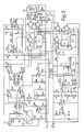
- Figure 4 shows a block diagram of the invention which incorporates the circuit shown in more detail in Figure 5.
- input pressure 38 is controlled by valve 39 to give an output pressure 40.
- a transducer 41 provides an electrical signal on line 42 which signal is amplified by amplifier 43 and fed to the comparator circuit and logic circuit 44. The output of the transducer 41 is a measure of the pressure in the line 40.
- An input signal in the range 4-20 mA is supplied on lines 45 to a power rail control and energy storage circuit 46.
- the main circuitry is fed via lines 47.
- the block 46 is connected to the comparator circuit and logic circuit 44.
- the minimum pressure setting can be adjusted by setter 48 with the input at 4 mA, and similarly the maximum pressure can be set by adjusting setter 49 with the input at 20 mA.
- the output of 44 is used to control the relay driver circuitry 50, which in turn controls the inlet and outlet Reedex (RTM) valves 51, 52. These valves control the pressure in the control volume 53, so as to control the output pressure 40.
- RTM Reedex
- this diagram can be split into two sections, the analogue circuitry and the digital circuitry, the analogue circuitry is on the left hand side of the circuit diagram and the digital on the right.
- the digital circuitry is continuously powered but the analogue is not, since very little current is used in CMOS digital circuitry.
- C1 is the storage capacitor from which energy is taken to power the circuitry when the loop signal is valid whilst at a lower level than that required to power the electronics.
- the supply rail potential is set by zener diode D11 in conjunction with the potential divider network R3, R4, R5.
- the rail potential is controlled via IC1b TR6, R1, R30 and LED1 and is set so that via R3, R4, R5 the same potential on D11 appears across R5.
- IC1a is configured in standard Schmitt trigger configuration to detect that sufficient rail volts are present to power the analogue circuitry; if this is not the case then the output of IC1a goes high, in which state the analogue circuitry is powered down allowing the capacitor C1 to recharge.
- IC5a supplies the excitation current to the transducer T, the output of the transducer is amplified and compared with the desired set point, which is set by the combination of the loop signal acting on P2, R38 and R40.
- the circuit includes an adaptive deadzone controller, in which, when power is applied to the analogue circuitry the deadzone is narrow therefore allowing one of the valves to go active. 5 mS + 10 ⁇ S after power is applied, 5 mS set by R12, C4, 10 ⁇ S set by R43, C8; TR7 is turned on widening the deadzone tending to turn valves off. The extra 10 ⁇ S is required to ensure that the deadzone is not changing when the valve activation status is being latched into IC3.
- the deadzone itself is controlled via R31, R32, R33, R36, R28, P3 and TR7. If TR7 is off then R28 and P3 are in circuit drawing very little current through resistors R31, R32, R34 & R36.
- One input is taken from IC3 which is the inverse of the signal from IC2 c or d and the other is taken from IC4b.
- the time period set by IC7a serves two purposes: it locks out the activation signal to the valves via IC3 which ensures that the valves are not falsely triggered when the pressure changes or when the supply rail glitches when one valve opens. Also it sets the minimum opening time of either valve which in turn controls the resolution achievable.
- IC7a times out the valves are kept open by the 25 KHz pulses from IC8a via IC4c. The mark space ratio of these pulses is designed to minimise power consumption whilst keeping the valve open.
- valves Built around the valves is a circuit which allows the energy stored in the valve coils to 'free wheel', ie when the 25 KHz pulse goes low a back emf is generated in the coil in accordance with Lenz's law, which is in the opposite direction to normal current flow. As such the current can flow through the Schottky diodes and back into the coil, keeping the valves open when no power is applied.
- micromotors are characterised by extremely low torque and high operating speeds and it would be necessary therefore to use a step down gear box, typically a 50,000:1 gear box to provide sufficient torque to operate the valve.
- step down gear box typically a 50,000:1 gear box to provide sufficient torque to operate the valve.
- switching piezoelectric or other low current drain valves could be used.
Landscapes
- Physics & Mathematics (AREA)
- Fluid Mechanics (AREA)
- General Physics & Mathematics (AREA)
- Engineering & Computer Science (AREA)
- Automation & Control Theory (AREA)
- Control Of Fluid Pressure (AREA)
- Supply Devices, Intensifiers, Converters, And Telemotors (AREA)
Applications Claiming Priority (2)
| Application Number | Priority Date | Filing Date | Title |
|---|---|---|---|
| GB888811123A GB8811123D0 (en) | 1988-05-11 | 1988-05-11 | Pressure regulator |
| GB8811123 | 1988-05-11 |
Publications (3)
| Publication Number | Publication Date |
|---|---|
| EP0341861A2 true EP0341861A2 (de) | 1989-11-15 |
| EP0341861A3 EP0341861A3 (de) | 1991-01-09 |
| EP0341861B1 EP0341861B1 (de) | 1993-03-10 |
Family
ID=10636707
Family Applications (1)
| Application Number | Title | Priority Date | Filing Date |
|---|---|---|---|
| EP89304182A Expired - Lifetime EP0341861B1 (de) | 1988-05-11 | 1989-04-26 | Zweidraht-Strom-Druckwandler mit Energiespeicherung |
Country Status (6)
| Country | Link |
|---|---|
| US (1) | US4951705A (de) |
| EP (1) | EP0341861B1 (de) |
| CA (1) | CA1335116C (de) |
| DE (1) | DE68905228T2 (de) |
| ES (1) | ES2039852T3 (de) |
| GB (1) | GB8811123D0 (de) |
Cited By (3)
| Publication number | Priority date | Publication date | Assignee | Title |
|---|---|---|---|---|
| EP0503894A1 (de) * | 1991-03-13 | 1992-09-16 | Watson Smith Limited | Elektrohydraulischer Wandler |
| EP0943811B1 (de) * | 1998-03-17 | 2005-03-09 | Bürkert Werke GmbH & Co. | Binärer elektrisch ansteuerbarer fluidischer Leistungsverstärker |
| WO2015007318A1 (en) * | 2013-07-18 | 2015-01-22 | Abb Technology Ltd | Discrete pilot stage valve arrangement with fail freeze mode |
Families Citing this family (18)
| Publication number | Priority date | Publication date | Assignee | Title |
|---|---|---|---|---|
| JP2001060114A (ja) * | 1999-08-24 | 2001-03-06 | Smc Corp | 圧力制御装置 |
| JP3634733B2 (ja) * | 2000-09-22 | 2005-03-30 | Smc株式会社 | 流体圧力調整装置 |
| US7505818B1 (en) * | 2001-09-07 | 2009-03-17 | Siemens Energy & Automation, Inc. | Converter method, system and apparatus |
| US6779541B2 (en) * | 2001-10-12 | 2004-08-24 | Smc Kabushiki Kaisha | Fluid pressure regulator |
| US20060045749A1 (en) * | 2004-08-30 | 2006-03-02 | Powermate Corporation | Air compressor utilizing an electronic control system |
| US7481627B2 (en) * | 2004-08-30 | 2009-01-27 | Mat Industries Llc | Air compressor tools that communicate with an air compressor |
| EP1893950B1 (de) * | 2005-06-15 | 2018-08-08 | Aquatrip Pty Ltd | Fluidströmungsmesser |
| US20090309054A1 (en) * | 2008-06-11 | 2009-12-17 | Automatic Switch Company | System and method of operating a solenoid valve at minimum power levels |
| US8381760B2 (en) * | 2008-07-14 | 2013-02-26 | Emerson Electric Co. | Stepper motor valve and method of control |
| US8746275B2 (en) | 2008-07-14 | 2014-06-10 | Emerson Electric Co. | Gas valve and method of control |
| DE102010056277B4 (de) * | 2010-12-24 | 2014-04-17 | Abb Technology Ag | Absperrarmatur |
| US20140174551A1 (en) * | 2012-08-28 | 2014-06-26 | Westport Power Inc. | Variable Gas Pressure Regulator |
| US10409298B2 (en) * | 2017-04-27 | 2019-09-10 | Marotta Controls, Inc. | Electronically controlled regulator |
| US10940447B2 (en) * | 2017-06-30 | 2021-03-09 | Pulsair Systems, Inc. | Control circuit for stopping the flow of fluid in a primary circuit, and related methods and devices |
| US20190346867A1 (en) * | 2018-05-14 | 2019-11-14 | Critical Systems, Inc. | Pressure control for gas system payback |
| IL268254B2 (en) * | 2019-07-24 | 2024-10-01 | Ham Let Israel Canada Ltd | Fluid-flow control device |
| CN110989707A (zh) * | 2019-11-07 | 2020-04-10 | 上海空间推进研究所 | 一种航天器轨控管路压强的安全管理方法 |
| JP7424322B2 (ja) * | 2021-01-19 | 2024-01-30 | Smc株式会社 | 流体圧力制御装置 |
Family Cites Families (12)
| Publication number | Priority date | Publication date | Assignee | Title |
|---|---|---|---|---|
| US2806481A (en) * | 1953-04-08 | 1957-09-17 | Norgren Co C A | Pilot controlled pressure regulator |
| US2994334A (en) * | 1959-08-13 | 1961-08-01 | John H Loveless | Air servo valve |
| BE651220A (de) * | 1963-08-02 | 1900-01-01 | ||
| US3369561A (en) * | 1966-05-04 | 1968-02-20 | Halliburton Co | System for automatic regulation of flow rate and pressure at a remote location |
| US3456669A (en) * | 1966-10-20 | 1969-07-22 | Fisher Governor Co | Piezoelectric transducer |
| US4325399A (en) * | 1979-11-15 | 1982-04-20 | Rosemount Inc. | Current to pressure converter apparatus |
| ZA815442B (en) * | 1980-08-18 | 1982-09-29 | Dynamic Air | Fluid regulator |
| EP0057581A3 (de) * | 1981-02-02 | 1982-09-01 | Grove Valve And Regulator Company | Verfahren und Vorrichtung für die Steuerung eines Regulierventils, das auf Druck anspricht |
| US4510848A (en) * | 1982-09-30 | 1985-04-16 | General Electric Company | Shear-type fail-fixed servovalve |
| US4509547A (en) * | 1983-02-22 | 1985-04-09 | The Babcock & Wilcox Company | Control system for an electro-pneumatic converter |
| JPS6184715A (ja) * | 1984-10-02 | 1986-04-30 | Tlv Co Ltd | 自動設定減圧弁 |
| JPS61173319A (ja) * | 1985-01-26 | 1986-08-05 | Shoketsu Kinzoku Kogyo Co Ltd | 流体用レギユレ−タ |
-
1988
- 1988-05-11 GB GB888811123A patent/GB8811123D0/en active Pending
-
1989
- 1989-04-26 EP EP89304182A patent/EP0341861B1/de not_active Expired - Lifetime
- 1989-04-26 ES ES198989304182T patent/ES2039852T3/es not_active Expired - Lifetime
- 1989-04-26 DE DE8989304182T patent/DE68905228T2/de not_active Expired - Lifetime
- 1989-05-04 CA CA000598684A patent/CA1335116C/en not_active Expired - Fee Related
- 1989-05-08 US US07/349,424 patent/US4951705A/en not_active Expired - Lifetime
Cited By (7)
| Publication number | Priority date | Publication date | Assignee | Title |
|---|---|---|---|---|
| EP0503894A1 (de) * | 1991-03-13 | 1992-09-16 | Watson Smith Limited | Elektrohydraulischer Wandler |
| US5370152A (en) * | 1991-03-13 | 1994-12-06 | Watson Smith Limited | I/P converters |
| EP0943811B1 (de) * | 1998-03-17 | 2005-03-09 | Bürkert Werke GmbH & Co. | Binärer elektrisch ansteuerbarer fluidischer Leistungsverstärker |
| WO2015007318A1 (en) * | 2013-07-18 | 2015-01-22 | Abb Technology Ltd | Discrete pilot stage valve arrangement with fail freeze mode |
| CN105593536A (zh) * | 2013-07-18 | 2016-05-18 | Abb技术有限公司 | 具有故障冻结模式的分立式先导级阀装置 |
| US9523376B2 (en) | 2013-07-18 | 2016-12-20 | Abb Schweiz Ag | Discrete pilot stage valve arrangement with fail freeze mode |
| CN105593536B (zh) * | 2013-07-18 | 2017-07-07 | Abb 技术有限公司 | 具有故障冻结模式的分立式先导级阀装置 |
Also Published As
| Publication number | Publication date |
|---|---|
| ES2039852T3 (es) | 1993-10-01 |
| EP0341861A3 (de) | 1991-01-09 |
| GB8811123D0 (en) | 1988-06-15 |
| DE68905228D1 (de) | 1993-04-15 |
| US4951705A (en) | 1990-08-28 |
| DE68905228T2 (de) | 1993-06-17 |
| EP0341861B1 (de) | 1993-03-10 |
| CA1335116C (en) | 1995-04-04 |
Similar Documents
| Publication | Publication Date | Title |
|---|---|---|
| EP0341861B1 (de) | Zweidraht-Strom-Druckwandler mit Energiespeicherung | |
| US4253480A (en) | Pressure regulator for fluid pressures | |
| US5370152A (en) | I/P converters | |
| US4321946A (en) | Armature position monitoring and control device | |
| US4995585A (en) | Sanitary fitting | |
| US4579137A (en) | Electro-pneumatic current to pressure transducer and pneumatic and electronic control circuits therefor | |
| US20200217894A1 (en) | Diagnostic device and method for solenoid valves | |
| US6267349B1 (en) | Precision valve control | |
| US4035708A (en) | Stepping motor control circuit | |
| MY110390A (en) | Device for controlling the operational procedures of a vacuum toilet | |
| US5377497A (en) | Timed-off control apparatus and method | |
| US6262620B1 (en) | Driver circuitry for latching type valve and the like | |
| US5124566A (en) | Shutoff circuit for sensor controlled switch | |
| JPH02281527A (ja) | 電磁接触器の電子付勢装置 | |
| CA1200590A (en) | Valve converter/positioner with remote feedback and memory | |
| US4509547A (en) | Control system for an electro-pneumatic converter | |
| US4731996A (en) | Position transmitter for a pneumatic-pneumatic or electro-pneumatic converter | |
| US4215383A (en) | Current regulator for DC motors including sensitivity control means therefor | |
| JPS593364B2 (ja) | 振動式供給装置への供給電力を制御する出力制御装置 | |
| EP0128138B1 (de) | Pneumatisch gesteuertes, motorangetriebenes zahnärztliches gerät | |
| EP0872645B1 (de) | Elektrohydraulische Antriebseinrichtung zur Fernsteuerung eines hydraulischen Verteilers | |
| US523873A (en) | Fluid-pressure regulator | |
| SU773585A1 (ru) | Регул тор давлени дл насосной станции магистрального трубопровода | |
| KR200356409Y1 (ko) | 엑츄에이터 서보 컨트롤 시스템 | |
| JPH04171906A (ja) | ソレノイドの作動チエツク方法 |
Legal Events
| Date | Code | Title | Description |
|---|---|---|---|
| PUAI | Public reference made under article 153(3) epc to a published international application that has entered the european phase |
Free format text: ORIGINAL CODE: 0009012 |
|
| AK | Designated contracting states |
Kind code of ref document: A2 Designated state(s): BE DE ES FR GB IT NL SE |
|
| PUAL | Search report despatched |
Free format text: ORIGINAL CODE: 0009013 |
|
| AK | Designated contracting states |
Kind code of ref document: A3 Designated state(s): BE DE ES FR GB IT NL SE |
|
| 17P | Request for examination filed |
Effective date: 19901220 |
|
| 17Q | First examination report despatched |
Effective date: 19920720 |
|
| GRAA | (expected) grant |
Free format text: ORIGINAL CODE: 0009210 |
|
| ITF | It: translation for a ep patent filed | ||
| AK | Designated contracting states |
Kind code of ref document: B1 Designated state(s): BE DE ES FR GB IT NL SE |
|
| REF | Corresponds to: |
Ref document number: 68905228 Country of ref document: DE Date of ref document: 19930415 |
|
| ET | Fr: translation filed | ||
| REG | Reference to a national code |
Ref country code: ES Ref legal event code: FG2A Ref document number: 2039852 Country of ref document: ES Kind code of ref document: T3 |
|
| PLBE | No opposition filed within time limit |
Free format text: ORIGINAL CODE: 0009261 |
|
| STAA | Information on the status of an ep patent application or granted ep patent |
Free format text: STATUS: NO OPPOSITION FILED WITHIN TIME LIMIT |
|
| 26N | No opposition filed | ||
| EAL | Se: european patent in force in sweden |
Ref document number: 89304182.2 |
|
| REG | Reference to a national code |
Ref country code: GB Ref legal event code: IF02 |
|
| PGFP | Annual fee paid to national office [announced via postgrant information from national office to epo] |
Ref country code: DE Payment date: 20080502 Year of fee payment: 20 Ref country code: ES Payment date: 20080520 Year of fee payment: 20 |
|
| PGFP | Annual fee paid to national office [announced via postgrant information from national office to epo] |
Ref country code: IT Payment date: 20080428 Year of fee payment: 20 Ref country code: BE Payment date: 20080616 Year of fee payment: 20 |
|
| PGFP | Annual fee paid to national office [announced via postgrant information from national office to epo] |
Ref country code: SE Payment date: 20080408 Year of fee payment: 20 Ref country code: NL Payment date: 20080331 Year of fee payment: 20 |
|
| PGFP | Annual fee paid to national office [announced via postgrant information from national office to epo] |
Ref country code: FR Payment date: 20080414 Year of fee payment: 20 |
|
| PGFP | Annual fee paid to national office [announced via postgrant information from national office to epo] |
Ref country code: GB Payment date: 20080430 Year of fee payment: 20 |
|
| BE20 | Be: patent expired |
Owner name: *WATSON SMITH LTD Effective date: 20090426 |
|
| REG | Reference to a national code |
Ref country code: GB Ref legal event code: PE20 Expiry date: 20090425 |
|
| PG25 | Lapsed in a contracting state [announced via postgrant information from national office to epo] |
Ref country code: NL Free format text: LAPSE BECAUSE OF EXPIRATION OF PROTECTION Effective date: 20090426 |
|
| EUG | Se: european patent has lapsed | ||
| REG | Reference to a national code |
Ref country code: ES Ref legal event code: FD2A Effective date: 20090427 |
|
| NLV7 | Nl: ceased due to reaching the maximum lifetime of a patent |
Effective date: 20090426 |
|
| PG25 | Lapsed in a contracting state [announced via postgrant information from national office to epo] |
Ref country code: ES Free format text: LAPSE BECAUSE OF EXPIRATION OF PROTECTION Effective date: 20090427 |
|
| PG25 | Lapsed in a contracting state [announced via postgrant information from national office to epo] |
Ref country code: GB Free format text: LAPSE BECAUSE OF EXPIRATION OF PROTECTION Effective date: 20090425 |