EP0341816B1 - Einrichtung und Verfahren zur Prüfung einer Teilnehmerleitung - Google Patents
Einrichtung und Verfahren zur Prüfung einer Teilnehmerleitung Download PDFInfo
- Publication number
- EP0341816B1 EP0341816B1 EP89302978A EP89302978A EP0341816B1 EP 0341816 B1 EP0341816 B1 EP 0341816B1 EP 89302978 A EP89302978 A EP 89302978A EP 89302978 A EP89302978 A EP 89302978A EP 0341816 B1 EP0341816 B1 EP 0341816B1
- Authority
- EP
- European Patent Office
- Prior art keywords
- line
- unit
- exchange
- telephone
- voltage
- Prior art date
- Legal status (The legal status is an assumption and is not a legal conclusion. Google has not performed a legal analysis and makes no representation as to the accuracy of the status listed.)
- Expired - Lifetime
Links
Images

Classifications
-
- H—ELECTRICITY
- H04—ELECTRIC COMMUNICATION TECHNIQUE
- H04M—TELEPHONIC COMMUNICATION
- H04M3/00—Automatic or semi-automatic exchanges
- H04M3/22—Arrangements for supervision, monitoring or testing
- H04M3/26—Arrangements for supervision, monitoring or testing with means for applying test signals or for measuring
- H04M3/28—Automatic routine testing ; Fault testing; Installation testing; Test methods, test equipment or test arrangements therefor
- H04M3/30—Automatic routine testing ; Fault testing; Installation testing; Test methods, test equipment or test arrangements therefor for subscriber's lines, for the local loop
Definitions
- This invention relates to apparatus for, and a method of, measuring the transmission loss performance of a telephone line connecting a customer's telephone apparatus to a local exchange.
- the transmission loss performance of a telephone connection is often thought of as the loss between the points where the telephone apparatuses are connected at either end of the line. This loss is usually measured, in dBs, by means of an oscillator connected at one end of the line, and a level measuring set connected at the other end of the line. Although such loss measurements are useful in tracing faults or testing circuits, they do not give a complete picture of the customer's opinion because they do not include the electrical and acoustic losses of the telephone apparatus.
- a known method of testing a customer's line utilises a simple tone test (usually a mid-frequency tone such as 1600 Hz).
- a simple tone test usually a mid-frequency tone such as 1600 Hz.
- the known method requires two telephone lines, one line for testing and one line for control.
- two people are required, one at the customer's apparatus and one at the local exchange, and careful synchronisation is essential.
- the known method is difficult to administer, and is not applicable to all customer lines.
- the known method gives no information regarding other frequencies, at which problems may be present.
- a loss measurement that takes account of all the acoustic and electrical losses that comprise the connection between the two users would be more representative of the customer's perceived view of the transmission loss performance of the connection. Such a loss measurement is called a loudness rating.
- the aim of the invention is to provide a customer line tester which uses only a single telephone line, which is easier to use than known apparatus, and which gives a more comprehensive test result than known apparatus.
- the present invention provides apparatus for testing a telephone line between a customer's telephone and a local exchange associated therewith, the apparatus comprising a field unit positionable between the customer's telephone and the line, an exchange unit positionable at the exchange, and control means associated with the field unit for controlling operation of the field unit and the exchange unit, characterised in that the field unit and the exchange unit each have means for transmitting a plurality of frequency tones down the line and means for measuring the voltage across the line, and the control means is effective to instruct the field unit to send a plurality of frequency tones to the exchange unit for measurement of the line voltage at each frequency, to instruct the exchange unit to send a plurality of frequency tones to the field unit for measurement of the line voltage at each frequency, to instruct the exchange unit to send the voltage values measured thereby to the field unit, and to calculate the loudness rating of the line from the measured voltage values.
- the transmission means of each of the units comprises a synthesiser adapted to produce a plurality of frequency tones.
- a respective filter and amplitude detector constitutes the voltage measuring means of each unit.
- control means is effective to instruct the synthesiser of the field unit to send a plurality of frequency tones to the filter and amplitude detector of the exchange unit for measurement of the line voltage at each frequency, to instruct the synthesiser of the exchange unit to send a plurality of frequency tones to the filter and amplitude detector of the field unit for measurement of the line voltage at each frequency, to instruct the exchange unit to send the voltage values measured by its filter and amplitude detector to the field unit, and to calculate the loudness rating of the line from said measured voltage values.
- the control means is effective to set the filter and amplitude detector of each of the units to each of the frequency tones in turn when the synthesiser of the other unit is sending frequency tones.
- control means further includes means for calculating the echo loss of the line.
- the means is effective to instruct the field unit to connect an impedance across the line, to instruct the synthesiser of the field unit to send a plurality of frequency tones to the exchange unit, to set the filter and amplitude detector of the exchange unit to each of the frequency tones in turn, to instruct the filter and amplitude detector of the exchange unit to measure the voltage across the line at each of the said frequencies, to instruct the exchange unit to send the measured voltage values to the field unit, and to calculate the echo loss of the line from said measured voltage values.
- the control means may further include means for calculating the round trip delay on the telephone line.
- the apparatus may further comprise an oscilloscope associated with the field unit, and wherein the control means is such as to send a predetermined pulse waveform over the telephone line, whereby the round trip delay can be determined by measuring the time between the incident and reflected pulses shown on the oscilloscope.
- the invention also provides a method of testing a telephone line between a customer's telephone and a local exchange associated therewith, the method comprising the steps of transmitting a plurality of frequency tones down the line from a master unit at one end of the line to a slave unit at the other end of the line, using the slave unit to measure the voltage across the line at each of said frequencies, transmitting a plurality of frequency tones from the slave unit to the master unit, using the master unit to measure the voltage across the line of each of said frequencies, transmitting the measured voltage values from the slave unit to the master unit, and using the measured voltage values to calculate the loudness rating for the line.
- the method further comprises the steps of connecting an impedance across the line, transmitting the plurality of frequency tones down the line from the master unit to the slave unit, using the slave unit to measure the voltage across the line at each of said frequencies, transmitting the measured voltage values from the slave unit to the master unit, and using the measured voltage values to calculate the echo loss of the line.
- the method further comprises the steps of sending a predetermined pulse waveform over the telephone line from the master unit to the slave unit and back to the master unit, and measuring the round trip delay of the line by measuring the time between the incident and reflected pulses shown on an oscilloscope associated with the master unit.
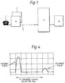
- Fig. 1 shows the customer line tester together with a customer's telephone apparatus 1, the local exchange 2 associated therewith, and a line 3 connecting the telephone apparatus to the local exchange.
- the tester is constituted by a field unit 4, a Merlin 5180 portable computer 5 for controlling the field unit, and an exchange unit 6, the exchange unit being controlled by a single board computer card (not shown).
- the tester's separate units 4 and 6 are connected at each end of the network.
- the local network is between the customer's line jack socket and the far side of the transmission bridge for an analogue exchange, and the far side of the codec for a digital exchange.
- the exchange unit 6 cannot be located at this reference point in the exchange 2, but on the end of another line in the exchange. This line can be considered for all purposes as having a negligible effect. Account can then be taken, for example in a digital exchange, of the gains and losses of the line card to make all calculations refer to the reference point.
- the local connection (line) 3 is whatever exists between the telephone 1 and the local exchange 2, be it a Private Branch Exchange (PBX) or anything else.
- PBX Private Branch Exchange
- TDX Telephone Exchange Digital
- the tester When used with a Telephone Exchange Digital (TDX) exchange it may be connected to either a four-wire line to perform delay, echo loss and loudness rating tests, or a two-wire line to perform loudness rating tests only. When used with all other exchange types, the tester can only be connected to a two-wire line to perform loudness rating tests.
- PBX Private Branch Exchange
- TDX Telephone Exchange Digital
- the computer 5 has two disc drives, drive A for receiving an applications disc, and drive B for receiving a results disc.
- the applications disc contains program software and data files for all commonly-used telephones.
- the program software controls the tester, and leads the user sequentially through the various test options.
- the exchange unit 6 can be connected for two-wire operation (for use with analogue and digital exchanges) or for four-wire operation (for use with digital exchanges).
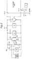
- the circuit layout of the exchange unit 6, which is shown in Fig. 3 illustrates these two alternative operational modes.
- the prime function of the tester is to measure the "loudness rating" of a customer's line.
- the term “loudness rating” describes the transmission loss performance of an end-to-end connection, and takes into account the different losses and frequency responses of the interconnecting circuits.
- a connection's Overall Loudness Rating consists of its Send Loudness Rating (SLR), its Receiver Loudness Rating (RLR), and the combined loss of the elements forming the connection between the SLR and RLR references points.
- SLR Send Loudness Rating
- RLR Receiver Loudness Rating
- the exchange unit 6 When the exchange unit 6 is situated in the local exchange 2, the SLR and RLR of the connection (line 3) can be measured by the field unit 4 when it has been connected at the customer's premises.
- Side tone is the term used to describe the receipt of speech by the user from the telephone's receiver when the user speaks into the microphone.
- the receipt of side tone by the user makes the telephone instrument seem operative, although the amount of side tone received may influence the user's perception of the transmission loss performance of the connection. Too much side tone tends to cause the user to speak quieter, or to hold the telephone handset further away from the mouth, resulting in a possible decrease in the received speech at the listener's telephone.
- the side tone is too high, the background noise observed by the user can be enhanced to an undesirable level, resulting in the received speech being masked, and possibly appearing faint to the customer. This problem has been encountered with some digital PBX installations. Too little side tone can cause the telephone user to speak too loudly, resulting in the distant customer's discomfort.
- STMR Side Tone Masking Rating
- the 'insertion loss' of the connection is also provided. This can be considered to be the loss presented (in dB) by the connection between the points of connection of the field unit 4 and the exchange unit 6.
- the tester displays a connection's insertion loss, it is referenced to an impedance of 600 ohms and an impedance that is dependant upon the telephone instrument being emulated.
- a loudness rating test can be made with the exchange unit 6 connected to a two-wire or a four-wire line. After connecting up the field unit 2, and switching on, the user will be led through the test, being offered options as necessary. These are responded to with a single keystroke of the computer 5.
- the applications disc is inserted into drive A and the results disc is inserted into drive B of the computer 5.
- the field unit 4, and then the computer 5 are turned on. 3.
- the program will boot up into the tester program and display the date and time. The question 'Is this correct, enter y or n' is displayed. Entering 'n' will allow the date and time to be modified under the program's prompting. 'y' is entered if the date and time are correct. 4.
- a prompt is given to connect the field unit 4 to the telephone 1 and the line 3. 5. This main menu is then displayed:
- the actual measurements carried out during the loudness rating test will now be described in greater detail with reference to Figs. 2 and 3.
- the first thing to be done is to measure the dc conditions at the customer's telephone 1 using the field unit 4.
- the voltage across the telephone line 3 and then, so as to determine the line current, the voltage across a 1 ohm resistor R1, in series with the telephone, are measured by a DC measurement unit 11 including op-amps and an analogue/digital convertor.
- the correct block of data for the line conditions and the operating characteristics of the customer's telephone is obtained from the relevant telephone data file.
- the line hold 12 is set so that the dc resistance of the telephone 1 is mimicked by the field unit 4.
- the relays RL1 and RL2 are then operated, connecting the tester to line.
- the field unit 4 tells the exchange unit 6 to receive a frequency sweep, and then tells it that it will send it the first frequency.
- the exchange unit 6 connects a 600 ohm termination R11, across the line by operating relay RL14.
- the field unit 4 sets its synthesiser 13 and filter/detector 14 to the correct frequency, and connects the synthesiser to the line 3 via relay RL6.
- the filter/detector 14 measures the voltage from the synthesiser 13 (with the relay RL5 off), the voltage across the line (with the relay RL5 on), and the phase across a 600 ohm resistor R2 associated with the synthesiser 13.
- the exchange unit 6 sets its filter/detector 22 to the correct frequency, and measures the level on the line via relay RL15.
- the modem 15 of the field unit 4 is then put on line via relay RL3, and the modem 21 of the exchange unit 6 is put on line via relay RL13. This is repeated for the 14 different frequencies in turn.
- the field unit 4 then tells the exchange unit 6 to send a frequency sweep, and then tells it to send the first frequency.
- the field unit 4 connects a 600 ohm termination R3 across the line via relay RL4.
- the exchange unit 6 sets its synthesiser 23 and filter/detector 22 to the correct frequency, and connects them to line via relays RL15 and RL16. It measures the voltage across the line.
- the field unit 4 sets its filter/detector 14 to the correct frequency, and measures the level on the line with the relay RL5 on. Both units 4 and 6 then put their modems 15 and 21 respectively on line. This is repeated for the 14 frequencies in turn.
- the field unit 4 then tells the exchange unit 6 to send the values it measured, and then calculates line impedance, insertion losses, and loudness ratings.
- relays RL18 and RL19 When the exchange unit 6 is set for connection to a four-wire line, relays RL18 and RL19 operate. The exchange unit 6 firstly measures the loss across its line transformers. Values are measured for each of the 14 frequencies. When the exchange unit 6 is set for connection to a two-wire line, relays RL18 and RL19 are not operated. Normally, the exchange unit 6 is looking at its telephone line for an incoming call. If in two-wire mode, it looks for ringing with its ring detector 24. If in four-wire mode, it looks for current being drawn from its line voltage feeding circuit.
- the exchange unit 6 When the exchange unit 6 finds a call, in two-wire mode, it connects its line hold 25 via relay RL12; and, in four-wire mode, it reverses the polarity of the line feeding voltage via relay RL21. It connects its modem 21 to line via relay RL13, and looks for the 'sign-on' message from the field unit 4. It is necessary for the field unit 4 to communicate with the exchange unit 6 every 30 seconds or so to keep the call established and prevent the exchange unit clearing down.
- connection's one-way delay Signals that are to be conveyed from the one end to the other end of a telephone connection experience a finite time delay as they travel through the interconnecting circuits forming the telephone connection between the users. This time delay is referred to as the connection's one-way delay.
- connection's one-way delay value in both directions of transmission gives the connection's round trip delay.
- the round trip delay between a Customer's telephone and the point of connection of the exchange unit 6 may be measured as is described below.
- Digital connections, and longer distance connections through the analogue network separate the directions of transmission, to allow for the regeneration of, or the amplification of, the signals that are to be transmitted.
- Two-wire to four-wire conversion circuits are used to provide four-wire working on such routes.
- Talker echo occurs when speech signals are reflected back to the talker from distant two-wire to four-wire conversion circuits.
- the subjective effect upon the talker is determined by the level of the speech echo, along with the time delay for the speech echo to be returned to the talker (round trip delay).
- This time delay (round trip delay) will be composed of the one-way delay up to the point where the speech signal is reflected, and the one-way delay within the path back to the talker.
- the round trip delay is less than a few milliseconds, then the speech echo increases the customer telephone apparatus side tone; but, as the end delay value increases, the speech echo becomes distinct from the side tone, and can become disturbing to the talker.
- Talker echo is normally controlled by ensuring that the receive-to-transmit loss introduced by a two-wire to four-wire conversion circuit is adequate to attenuate any echo signal to a level where it is not subjectively disturbing to the user.
- Echo loss is defined as the weighted loss value observed at the "equi-reference level" point, and for the British Telecom network this reference point is normally the O dBr point.
- a four-wire circuit is considered to be stable if it can reliably convey information between telephone users, without entering into a state of oscillation, and maintain a state of equilibrium during the time it is not in use but still in a state of activation.
- a four-wire circuit can be prevented from entering into a state of oscillation if sufficient loss is maintained across the two-wire to four-wire conversion circuit's four-wire termination. This loss is called “stability loss” and is measured, at a O dBr four-wire reference point, in the frequency range 0-4 KHz between the receive and transmit four-wire terminations with any impedance terminating the two wire.
- the tester can be used to carry out echo loss, stability loss and delay tests.
- the first two of these tests are carried out in the following manner:- An echo loss test can be made only if the exchange unit 6 is connected to a four-wire analogue junction on a digital exchange. After connecting up the field unit 6 and switching on, the user will be led through the test, being offered options as necessary. These are responded to with a single keystroke of computer 5.
- the following test sequence will then occur: 1.
- the applications disc is inserted into drive A and the results disc is inserted into drive B of the computer 5.
- the tester and then the computer 5 are turned on. 3.
- the program will boot up into the tester program and display the date and time. The question "Is this correct, enter y or n" is displayed.
- the field unit 4 tells the exchange unit 6 to do an echo loss sweep, and then tells it the first frequency to use.
- the field unit 4 connects the chosen termination across the line 3.
- the exchange unit 6 sets its synthesiser 23 and filter/detector 22 to the correct frequency, and connects them to the line 3 via relays RL15 and RL16. With its filter/detector 22 it measures the voltage sent to the line 3 (via relay RL15) and that received back from line 3 (via relay RL15). Both units 4 and 6 then put their modems 15 and 21 respectively on line. This is repeated for the 14 frequencies in turn.
- the field unit 4 tells the exchange unit 6 to send the values it measured, and then calculates the loss at each frequency, and then the echo loss.
- the delay test is carried out in the following manner: A delay test can only be made if the exchange unit 6 is connected to a four-wire analogue junction on a digital exchange. After connecting up the field unit 4 and switching on, the user will be led through the test, being offered options as necessary. These are responded to with a single keystroke of the computer 5. Although the line tester generates the incident pulse for this test, the returned pulse must be viewed, and the delay measured, on an electrically-isolated oscilloscope (not shown). A dual outlet adaptor is plugged into the customer's jack socket. Both the field unit 4 and the line socket test plug are connected to this. The electrically-isolated oscilloscope is connected to pins 2 and 5 of the line socket test plug.
- the results can be recorded in a file on a disc in drive B. This makes a character file that can be printed out or examined at some other time.
- the directory of the results files already stored and their contents can also be viewed.
- the question 'Store test results in a file on disc?, enter y or n' is displayed. Pressing 'y' will enter a sequence where details of the connection and the results will be stored on the results disc in drive B under a file name chosen by the user.
Landscapes
- Engineering & Computer Science (AREA)
- Signal Processing (AREA)
- Monitoring And Testing Of Exchanges (AREA)
- Maintenance And Management Of Digital Transmission (AREA)
- Financial Or Insurance-Related Operations Such As Payment And Settlement (AREA)
Claims (18)
- Vorrichtung zum Testen einer Telefonleitung (3) zwischen einem Kundentelefon (1) und einer örtlichen Vermittlungsstelle (2), die diesen zugeordnet ist, wobei die Vorrichtung eine Feldeinheit (4) aufweist, die zwischen dem Kundentelefon und der Leitung positionierbar ist, eine Vermittlungsstelleneinheit (6), die an der Vermittlungsstelle positionierbar ist, und eine Steuereinrichtung (5), die mit der Feldeinheit zum Steuern des Betriebes der Feldeinheit und der Vermittlungsstelleneinheit zugeordnet ist, dadurch gekennzeichnet, daß die Feldeinheit und die Vermittlungsstelleneinheit jeweils Einrichtungen (14, 22) zum Übermitteln einer Vielzahl von Frequenztönen über die Leitung aufweisen und eine Einrichtung (14, 22) zum Messen der Spannung auf der Leitung, wobei die Steuereinrichtung wirksam ist, um die Feldeinheit zu instruieren, eine Vielzahl von Frequenztönen zu der Vermittlungsstelleneinheit zur Messung einer Leitungsspannung bei jeder Frequenz zu senden, und um die Vermittlungsstelleneinheit zu instruieren, eine Vielzahl von Frequenztönen zu der Feldeinheit zur Messung der Leitungsspannung bei jeder Frequenz auszusenden, um die Vermittlungsstelleneinheit zu instruieren, die Spannungswerte, die dabei gemessen worden sind, der Feldeinheit zu senden und den Lautheitsgrad der Leitung aus den gemessenen Spannungswerten zu berechnen.
- Vorrichtung nach Anspruch 1, wobei die Übertragungseinrichtung einer jeden Einheit (4, 6) einen Synthesizer (13, 23) aufweist, der angepaßt ist, um eine Vielzahl von Frequenztönen zu erzeugen.
- Vorrichtung nach Anspruch 2, wobei jeder Synthesizer (13, 23) angepaßt ist, 14 Standardfrequenztöne zu erzeugen.
- Vorrichtung nach Anspruch 2 oder 3, wobei die Übertragungseinrichtung (13, 23) jeder Einheit (4, 6) ferner ein Modern (15, 21) aufweist.
- Vorrichtung nach einem der Ansprüche 1 bis 4, wobei ein Filter und ein Amplitudendetektor (14, 22) die Spannungsmeßeinrichtung einer jeden Einheit bildet.
- Vorrichtung nach Anspruch 5, wobei die Steuereinrichtung (5) wirksam ist, um jedes Filter und Amplitudendetektor (14, 22) auf eine gewünschte Frequenz einzustellen, bevor der Detektor die Spannung über die Leitung (3) mißt.
- Vorrichtung nach Anspruch 6, wobei die Steuereirrichtung (5) wirksam ist, den Synthesizer (13) der Feldeinheit (4) zu instruieren, eine Vielzahl von Frequenztönen zu dem Filter und dem Amplitudendetektor (22) der Vermittlungsstelleneinheit (6) zur Messung der Leitungsspannung bei jeder Frequenz zu senden, um den Synthesizer (23) der Vermittlungsstelleneinheit zu instruieren, eine Vielzahl von Frequenztönen zu dem Filter und dem Amplitudendetektor (14) der Feldeinheit zum Messen der Leitungsspannung bei jeder Frequenz zu senden, die Vermittlungsstelleneinheit zu instruieren die Spannungswerte, die durch ihren Filter und Amplitudendetektor gemessen worden sind, zu der Feldeinheit zu senden und den Lautheitsgrad der Leitung aus den gemessenen Spannungsworten zu berechnen.
- Vorrichtung nach Anspruch 7, wobei die Steuereinrichtung (5) wirksam ist, um das Filter und den Amplitudendetektor (14, 22) jeder der Einheiten (4, 6) auf jeden der Frequenztöne dann einzustellen, wenn der Synthesizer (23, 13) der anderen Einheit Frequenztöne sendet.
- Vorrichtung nach einem der Ansprüche 6 bis 8, wobei die Steuereinrichtung (5) weiterhin eine Einrichtung zum Berechnen des Echoverlustes der Leitung (3) einschließt.
- Vorrichtung nach Anspruch 9, wobei die Steuereinheit (5) wirksam ist, die Feldeinheit (4) zu instruieren, eine Impedanz über die Leitung (3) anzuschließen, den Synthesizer (13) der Feldeinheit zu instruieren, eine Vielzahl von Frequenztönen zu der Vermittlungsstelleneinheit (6) zu senden, das Filter und den Amplitudendetektor (22) der Vermittlungsstelleneinheit auf Jeden der Frequenztöne einzustellen, das Filter und den Amplitudendetektor der Vermittlungsstelleneinheit zu instruieren, die Spannung über die Leitung (3) bei jeder dieser Frequenzen zu messen, die Vermittlungsstelleneinheit zu instruieren, die gemessenen Spannungseinheiten zu der Feldeinheit zu senden, und den Echoverlust der Leitung aus den gemessenen Spannungswerten zu beurteilen.
- Vorrichtung nach einem der Ansprüche 6 bis 10, wobei die Steuereinrichtung (5) weiterhin eine Einrichtung zum Berechnen der Umlaufverzögerung auf der Telefonleitung (3) einschließt.
- Vorrichtung nach Anspruch 11, die weiterhin ein Oszilloskop aufweist, die der Feldeinheit (4) zugeordnet ist und wobei die Steuereinrichtung (5) in der Weise ausgestaltet ist, daß sie eine vorbestimmte Impulswelleform über die Telefonleitung (3) sendet, wobei die Umlaufverzögerung bestimmt werden kann durch Messen der Zeit zwischen dem Hin- und Rückimpuls, der auf dem Oszilloskop dargestellt wird.
- Vorrichtung nach einem der Ansprüche 1 bis 12, wobei ein Mikrocomputer (5) die Steuereinrichtung bildet.
- Vorrichtung nach Anspruch 13, wobei der Microcomputer (5) programmiert ist, daß auf Dateien zugegriffen werden kann, die Blocks von Daten beinhalten, die sich auf Betriebscharakteristiken eines jeden einer vorbestimmten Anzahl von Telefonen beziehen.
- Verfahren zum Testen einer Telefonleitung (3) zwischen einem Kundentelefon (1) und einer örtlichen Vermittlungsstelle (2), die diesem zugeordnet ist, wobei das Verfahren die Schritte der Übertragung einer Vielzahl von Frequenztönen über die Leitung von einer übergeordneten Einheit (4) an dem einen Ende der Leitung zu einer untergeordneten Einheit (6) am anderen Ende der Leitung umfaßt, das Benutzen der untergeordneten Einheit, um die Spannung an der Leitung bei jeder der Frequenzen zu messen, Übertragen einer Vielzahl von Frequenztönen von der untergeordneten Einheit zu der übergeordneten Einheit, Benutzen der übergeordneten Einheit zum Messen der Spannung an der Leitung bei jeder der Frequenzen, Übertragen der gemessenen Spannungswerte von der untergeordneten Einheit Zu der übergeordneten Einheit und Benutzen der gemessenen Spannungswerte, um die Lautheitsgrade für die Leitung zu berechnen.
- Verfahren nach Anspruch 15, das weiterhin die Schritte des Verbindens einer Impedanz über die Leitung (3) umfaßt, das Übertragen einer Vielzahl von Frequenztönen über die Leitung von der übergeordneten Einheit (4) zu der untergeordneten Einheit (6), Benutzen der untergeordneten Einheit, um die Spannung über die Leitung zu messen bei jeder der Frequenzen, Übertragen der gemessenen Spannungswerte von der untergeordneten Einheit zu der übergeordneten Einheit und Benutzen der gemessenen Spannungswerte, um den Echoverlust der Leitung zu berechnen.
- Verfahren nach Anspruch 15 oder 16, das weiterhin die Schritte des Sendens einer vorbestimmten Impulswellenform über die Telefonleitung (3) von der übergeordneten Einheit (4) zu der untergeordneten Einheit (6) und zurück Zu der übergeordneten Einheit aufweist und zum Messen der Umlaufverzögerung der Leitung durch Messen der Zeit zwischen dem Hin- und Rückimpuls, der auf einent, der übergeordneten Einheit zugeordneten Oszilloskop dargestellt wird.
- Verfahren nach einem der Ansprüche 15 bis 17, wobei es weiterhin die Schritte des Benutzens eines Mikrocomputers (5) aufweist zum Zugreifen auf Dateien, die Blocks von Daten bezüglich der Betriebseigenschaften einer vorbestimmten Anzahl von Telefonen enthalten, das Auffinden von Daten, die für das Kundentelefon (1) geeignet sind und Benutzen dieser Daten bei der Berechnung der Lautheitsgrade für die Leitung (3).
Applications Claiming Priority (2)
| Application Number | Priority Date | Filing Date | Title |
|---|---|---|---|
| GB888808623A GB8808623D0 (en) | 1988-04-12 | 1988-04-12 | Customer line tester |
| GB8808623 | 1988-04-12 |
Publications (2)
| Publication Number | Publication Date |
|---|---|
| EP0341816A1 EP0341816A1 (de) | 1989-11-15 |
| EP0341816B1 true EP0341816B1 (de) | 1994-06-01 |
Family
ID=10635057
Family Applications (1)
| Application Number | Title | Priority Date | Filing Date |
|---|---|---|---|
| EP89302978A Expired - Lifetime EP0341816B1 (de) | 1988-04-12 | 1989-03-23 | Einrichtung und Verfahren zur Prüfung einer Teilnehmerleitung |
Country Status (9)
| Country | Link |
|---|---|
| US (1) | US4924489A (de) |
| EP (1) | EP0341816B1 (de) |
| JP (1) | JPH01311654A (de) |
| AT (1) | ATE106646T1 (de) |
| AU (1) | AU616251B2 (de) |
| CA (1) | CA1311067C (de) |
| DE (1) | DE68915614T2 (de) |
| GB (1) | GB8808623D0 (de) |
| NZ (1) | NZ228702A (de) |
Families Citing this family (20)
| Publication number | Priority date | Publication date | Assignee | Title |
|---|---|---|---|---|
| US5111497A (en) * | 1990-09-17 | 1992-05-05 | Raychem Corporation | Alarm and test system for a digital added main line |
| US5246383A (en) * | 1990-09-17 | 1993-09-21 | Raychem Corporation | Gel filled electrical connector |
| US5195125A (en) * | 1990-09-17 | 1993-03-16 | Raychem Corporation | Gel filled RJ11 connector |
| US5376019A (en) * | 1990-09-17 | 1994-12-27 | Raychem Corporation | Gel filled modular electrical connecting block |
| US5073919A (en) * | 1990-10-10 | 1991-12-17 | Teradyne, Inc. | Automatically testing telephone lines |
| US5103473A (en) * | 1991-04-03 | 1992-04-07 | Harris Corporation | Telephone system communication mechanism employing central office sleeve lead |
| US5343461A (en) * | 1991-08-27 | 1994-08-30 | Ameritech Services, Inc. | Full duplex digital transmission facility loop-back test, diagnostics and maintenance system |
| WO1993009612A1 (en) * | 1991-10-30 | 1993-05-13 | Raychem Corporation | Alarm and test system with improved coupling circuit for a digital added main line |
| US5384822A (en) * | 1992-06-30 | 1995-01-24 | At&T Corp. | Computer controlled test facility for a telecommunication switch |
| US5357556A (en) * | 1992-08-10 | 1994-10-18 | Pacific Bell | System and method for telephone network testing |
| CA2188879C (en) * | 1994-05-17 | 2000-11-21 | Anthony Gladwyn Dunn | Network termination equipment |
| US6278729B1 (en) * | 1997-02-10 | 2001-08-21 | International Business Machines Corporation | Method and apparatus for testing a communications line in a data processing system |
| US7006445B1 (en) * | 1997-07-07 | 2006-02-28 | Legerity, Inc. | Device and method for determining characteristics of a digital subscriber line |
| CN1070329C (zh) * | 1998-03-11 | 2001-08-29 | 广东省电信科学技术研究院 | 市话用户线报障集中自动测试的方法 |
| US6084944A (en) * | 1998-06-08 | 2000-07-04 | Lucent Technologies Inc. | System for automated voice terminal recognition and dynamic representation on a test facility |
| DE59800423D1 (de) * | 1998-07-09 | 2001-02-08 | Wandel & Goltermann Man Holdin | Verfahren zur Dämpfungsmessung in digitalen Übertragungsleitungen |
| GB0005227D0 (en) * | 2000-03-03 | 2000-04-26 | Teradyne Inc | Technique for estimatio of insertion loss |
| GB2365253B (en) * | 2000-07-19 | 2004-06-16 | Teradyne Inc | Method of performing insertion loss estimation |
| DE10251143A1 (de) * | 2002-10-31 | 2004-05-13 | Deutsche Telekom Ag | Verfahren und Prüfvorrichtung zum Überprüfen für eine Kommunikationsverbindung nach Zeittaktintervallen |
| US6971897B1 (en) | 2003-10-29 | 2005-12-06 | Tyco Electronics Corporation | Gel-filled telephone jack |
Family Cites Families (7)
| Publication number | Priority date | Publication date | Assignee | Title |
|---|---|---|---|---|
| DE2001722C3 (de) * | 1970-01-15 | 1978-11-02 | Standard Elektrik Lorenz Ag, 7000 Stuttgart | Verfahren zum Messen der Dämpfung von Zweidraht-Fernmelde-, insbesondere Fernsprechleitungen |
| US3920935A (en) * | 1970-12-21 | 1975-11-18 | Oskar Vierling | Method for measuring the frequency-dependent attenuation of a telecommunications line, especially a two-wire line |
| AU474978B2 (en) * | 1971-04-21 | 1976-08-05 | Nv. Philips' Gloeilampenfabrieken | Transmission system forthe transmission of signals between two terminal stations through a transmission line including repeater stations |
| US4467148A (en) * | 1982-02-02 | 1984-08-21 | Network Control Corporation | Telephone line analyzer |
| GB2121549B (en) * | 1982-06-01 | 1985-08-29 | Standard Telephones Cables Ltd | Apparatus for determining the loudness rating of a telephone system |
| US4558188A (en) * | 1983-12-21 | 1985-12-10 | Stuparits Jeffrey J | Arrangement for line jumper testing |
| DE3444872C2 (de) * | 1984-12-08 | 1987-05-14 | Vierling, Oskar, Prof. Dr.Phil.Habil., 8553 Ebermannstadt | Schaltungsanordnung zum Prüfen von Teilnehmer-Anschlußleitungen |
-
1988
- 1988-04-12 GB GB888808623A patent/GB8808623D0/en active Pending
-
1989
- 1989-03-23 AT AT89302978T patent/ATE106646T1/de not_active IP Right Cessation
- 1989-03-23 DE DE68915614T patent/DE68915614T2/de not_active Expired - Fee Related
- 1989-03-23 EP EP89302978A patent/EP0341816B1/de not_active Expired - Lifetime
- 1989-04-06 US US07/333,921 patent/US4924489A/en not_active Expired - Fee Related
- 1989-04-07 CA CA000596039A patent/CA1311067C/en not_active Expired - Lifetime
- 1989-04-10 AU AU32605/89A patent/AU616251B2/en not_active Ceased
- 1989-04-10 JP JP1091717A patent/JPH01311654A/ja active Pending
- 1989-04-12 NZ NZ228702A patent/NZ228702A/en unknown
Also Published As
| Publication number | Publication date |
|---|---|
| JPH01311654A (ja) | 1989-12-15 |
| AU3260589A (en) | 1989-10-19 |
| NZ228702A (en) | 1990-11-27 |
| EP0341816A1 (de) | 1989-11-15 |
| CA1311067C (en) | 1992-12-01 |
| DE68915614T2 (de) | 1994-10-13 |
| US4924489A (en) | 1990-05-08 |
| ATE106646T1 (de) | 1994-06-15 |
| DE68915614D1 (de) | 1994-07-07 |
| GB8808623D0 (en) | 1988-05-11 |
| AU616251B2 (en) | 1991-10-24 |
Similar Documents
| Publication | Publication Date | Title |
|---|---|---|
| EP0341816B1 (de) | Einrichtung und Verfahren zur Prüfung einer Teilnehmerleitung | |
| US4639557A (en) | Remote testing system for electrical circuits | |
| US5652712A (en) | Method and apparatus for calibration of digital test equipment | |
| US4912755A (en) | Line current test device | |
| US7149285B2 (en) | Dynamic, automated double-ended system and method for testing and qualifying metallic telecommunication loops | |
| US4105995A (en) | Digitally controlled transmission impairment measuring apparatus | |
| US4413163A (en) | Portable line tester for telecommunication system | |
| US20040086086A1 (en) | Automated subscriber loop identification and data transfer for subscriber loop testing | |
| US6385296B1 (en) | System to test a connection in a telephone network | |
| US4445007A (en) | Remote testing of subscriber line interface circuits | |
| US5778050A (en) | Portable line test telephone | |
| US6256294B1 (en) | User selectable overlap and enbloc dialing of ISDN line | |
| WO1992003003A1 (en) | Electrical apparatus for simulating functions of a complex switching device | |
| EP0049287A1 (de) | Tragbares telefonleitungstestgerät | |
| EP0880258B1 (de) | Ferntesten von einer Kommunikationsleitung | |
| US3430008A (en) | Apparatus for testing a telephone circuit | |
| EP0881855A2 (de) | ISDN Rückrufvorrichtung zum Testen einer Fernsprechleitung | |
| US1261096A (en) | Testing apparatus. | |
| Favin et al. | The picturephone® system: Line and trunk maintenance arrangements | |
| JPH0649004Y2 (ja) | 電話回線の簡易模擬アダプタ | |
| JP2776600B2 (ja) | 時刻設定自動制御方式 | |
| Bartelink et al. | One-man multifrequency transmission measurements | |
| JPS63240251A (ja) | 自動終端平衡反射減衰量測定方式 | |
| JP2000244374A (ja) | 通信装置の送受信試験方法 | |
| JPS58170232A (ja) | デイジタル端局装置における平衡回路網 |
Legal Events
| Date | Code | Title | Description |
|---|---|---|---|
| PUAI | Public reference made under article 153(3) epc to a published international application that has entered the european phase |
Free format text: ORIGINAL CODE: 0009012 |
|
| AK | Designated contracting states |
Kind code of ref document: A1 Designated state(s): AT BE CH DE ES FR GB GR IT LI NL SE |
|
| 17P | Request for examination filed |
Effective date: 19900424 |
|
| 17Q | First examination report despatched |
Effective date: 19920723 |
|
| GRAA | (expected) grant |
Free format text: ORIGINAL CODE: 0009210 |
|
| AK | Designated contracting states |
Kind code of ref document: B1 Designated state(s): AT BE CH DE ES FR GB GR IT LI NL SE |
|
| PG25 | Lapsed in a contracting state [announced via postgrant information from national office to epo] |
Ref country code: IT Free format text: LAPSE BECAUSE OF FAILURE TO SUBMIT A TRANSLATION OF THE DESCRIPTION OR TO PAY THE FEE WITHIN THE PRESCRIBED TIME-LIMIT;WARNING: LAPSES OF ITALIAN PATENTS WITH EFFECTIVE DATE BEFORE 2007 MAY HAVE OCCURRED AT ANY TIME BEFORE 2007. THE CORRECT EFFECTIVE DATE MAY BE DIFFERENT FROM THE ONE RECORDED. Effective date: 19940601 Ref country code: NL Effective date: 19940601 Ref country code: GR Free format text: LAPSE BECAUSE OF FAILURE TO SUBMIT A TRANSLATION OF THE DESCRIPTION OR TO PAY THE FEE WITHIN THE PRESCRIBED TIME-LIMIT Effective date: 19940601 Ref country code: ES Free format text: THE PATENT HAS BEEN ANNULLED BY A DECISION OF A NATIONAL AUTHORITY Effective date: 19940601 Ref country code: AT Effective date: 19940601 Ref country code: CH Effective date: 19940601 Ref country code: LI Effective date: 19940601 Ref country code: BE Effective date: 19940601 |
|
| REF | Corresponds to: |
Ref document number: 106646 Country of ref document: AT Date of ref document: 19940615 Kind code of ref document: T |
|
| REF | Corresponds to: |
Ref document number: 68915614 Country of ref document: DE Date of ref document: 19940707 |
|
| PG25 | Lapsed in a contracting state [announced via postgrant information from national office to epo] |
Ref country code: SE Effective date: 19940901 |
|
| REG | Reference to a national code |
Ref country code: CH Ref legal event code: PL |
|
| ET | Fr: translation filed | ||
| NLV1 | Nl: lapsed or annulled due to failure to fulfill the requirements of art. 29p and 29m of the patents act | ||
| PLBE | No opposition filed within time limit |
Free format text: ORIGINAL CODE: 0009261 |
|
| STAA | Information on the status of an ep patent application or granted ep patent |
Free format text: STATUS: NO OPPOSITION FILED WITHIN TIME LIMIT |
|
| 26N | No opposition filed | ||
| PGFP | Annual fee paid to national office [announced via postgrant information from national office to epo] |
Ref country code: FR Payment date: 19960208 Year of fee payment: 8 |
|
| PGFP | Annual fee paid to national office [announced via postgrant information from national office to epo] |
Ref country code: GB Payment date: 19960216 Year of fee payment: 8 |
|
| PGFP | Annual fee paid to national office [announced via postgrant information from national office to epo] |
Ref country code: DE Payment date: 19960227 Year of fee payment: 8 |
|
| PG25 | Lapsed in a contracting state [announced via postgrant information from national office to epo] |
Ref country code: GB Effective date: 19970323 |
|
| GBPC | Gb: european patent ceased through non-payment of renewal fee |
Effective date: 19970323 |
|
| PG25 | Lapsed in a contracting state [announced via postgrant information from national office to epo] |
Ref country code: FR Free format text: LAPSE BECAUSE OF NON-PAYMENT OF DUE FEES Effective date: 19971128 |
|
| PG25 | Lapsed in a contracting state [announced via postgrant information from national office to epo] |
Ref country code: DE Effective date: 19971202 |
|
| REG | Reference to a national code |
Ref country code: FR Ref legal event code: ST |