EP0341815A2 - Verfahren zum Gegen-Schwerkraft-Giessen - Google Patents
Verfahren zum Gegen-Schwerkraft-Giessen Download PDFInfo
- Publication number
- EP0341815A2 EP0341815A2 EP89302738A EP89302738A EP0341815A2 EP 0341815 A2 EP0341815 A2 EP 0341815A2 EP 89302738 A EP89302738 A EP 89302738A EP 89302738 A EP89302738 A EP 89302738A EP 0341815 A2 EP0341815 A2 EP 0341815A2
- Authority
- EP
- European Patent Office
- Prior art keywords
- mould
- metal
- vacuum
- pattern
- container
- Prior art date
- Legal status (The legal status is an assumption and is not a legal conclusion. Google has not performed a legal analysis and makes no representation as to the accuracy of the status listed.)
- Withdrawn
Links
Images

Classifications
-
- B—PERFORMING OPERATIONS; TRANSPORTING
- B22—CASTING; POWDER METALLURGY
- B22D—CASTING OF METALS; CASTING OF OTHER SUBSTANCES BY THE SAME PROCESSES OR DEVICES
- B22D18/00—Pressure casting; Vacuum casting
- B22D18/06—Vacuum casting, i.e. making use of vacuum to fill the mould
-
- B—PERFORMING OPERATIONS; TRANSPORTING
- B22—CASTING; POWDER METALLURGY
- B22C—FOUNDRY MOULDING
- B22C7/00—Patterns; Manufacture thereof so far as not provided for in other classes
- B22C7/02—Lost patterns
- B22C7/023—Patterns made from expanded plastic materials
Definitions
- This invention relates to mould-immersion type counter-gravity casting processes and more specifically to such processes wherein resin-bonded particulate moulds therefor are used as specified in the preamble of claim 1, for example as disclosed in US-A-4,340,108.
- the so-called "lost foam” process involves pouring molten metal into a foamed plastics pattern surrounded by a porous, unbonded sand mould.
- the molten metal vaporizes the pattern and replaces it in the sand before the sand collapses.
- the solidified metal thus assumes the shape of the foamed plastic pattern and the pattern destruction products escape into the porous mould.
- the "lost foam” process has been proposed for use in conjunction with both gravity and counter-gravity poured metal as exemplified by US-A-4,085,790 and US-A-4,616,689, respectively.
- US-A-4,754,798 describes a casting process wherein a disposable pattern (e.g., wax or foam,) is embedded in a lightly-bonded, self-supporting, sand mould having sufficient porosity to receive liquid and vapours generated upon destruction of the pattern.
- a disposable pattern e.g., wax or foam
- Low-temperature heating of the mould/pattern prior to casting, causes the pattern to become fluid and disperse into the pores of the sand mould as well as flow out of the gate and sprue openings in it. Thereafter, metal is cast into the mould using either gravity or counter-gravity techniques.
- the mould-immersion, counter-gravity casting process is described in US-A-4,340,108, inter alia , and involves sealing a porous, gas-permeable mould in the mouth of a vacuum chamber, immersing the underside of the mould in an underlying molten metal pool and evacuating the chamber to draw molten metal through one or more ingate(s) in the underside of the mould into one or more mould cavities formed within the mould.
- the mould disclosed in US-A-4,340,108 comprises a rigid, self-supporting, particulate (e.g., sand) mass formed by a shell-moulding process wherein resin binders (i.e., thermoset resins) are used to bind the particles together.
- a process for the vacuum counter-gravity casting of metal according to the present invention is characterised by the features specified in the characterising portion of claim 1.
- the present invention is an improvement on the mould-immersion type counter-gravity casting process and comprehends essentially forming and curing the mould in-situ in the vacuum chamber used during the casting step rather than in a separate operation.
- the improved process is similar to other mould-immersion type counter-gravity casting processes in that it involves the principal steps of:
- the mould is both formed and cured in-situ in the self-same container as defines the vacuum chamber used during the casting step.
- the container is provided with a porous, gas-permeable wall, spaced from the mouth of the container to provide a chamber between the wall and the mouth for receiving mould-forming particulates containing chemically-curable binder-forming precursors.
- the pores in the wall are generally smaller than the grains of particulate material so that gas can freely pass through the wall but particulates cannot enter and plug the wall so as to prevent the passage of gas therethrough.
- a gas plenum is provided on the rear of the wall, i.e., opposite the particulate-containing-chamber side of the wall.
- the container is first oriented so that its mouth faces upwardly to receive mould-forming particulates dispensed therein.
- a temporary, removable upstanding frame-like rim is provided at the mouth of the container to effectively increase the depth of the particulate-receiving chamber and thereby provide means for shaping a mass of particulates into a mould portion which protrudes out of the chamber beyond the mouth of the container as will be described hereinafter in more detail.
- a gasifiable pattern of the type commonly used in the "lost foam” process (e.g., polystyrene foam), is then positioned in the chamber (i.e., between the porous wall and the mouth of the container) and enveloped by a mass of mould-forming particulate material as by blowing, deposition, fluidization, vibration or combinations thereof as is well known in the practice of embedding patterns in the "lost-foam” process.
- the mould-forming particulate material is mixed with a chemically-curable precursor of the resin used to bond the particulates together.
- the particulates are preferably coated with the precursor.
- a curing gas is passed through the porous wall of the container and through the particulate bed to catalyze or react (i.e., depending on the chemistry of particular resin system used) with the curable precursor of the resin binder therein.
- Sufficient curing gas is passed to convert the precursors into the bonding resin for holding the particulates together in a unified bonded mass surrounding the pattern.
- the temporary rim is then removed from the mouth of the container to leave a free-standing portion of the unified mass protruding beyond the mouth of the container.
- the container is inverted to position the protruding portion of the mould beneath the container mouth and immediately above an underlying pool of molten metal.
- the protruding portion of the mould is then immersed in an underlying pool of molten metal, and sufficient vacuum established behind the porous wall (i.e., on the opposite side of the mould) to reduce the pressure in the chamber and draw molten metal from the pool into the mould cavity.
- the molten metal drawn into the mould vaporises and displaces the pattern therein.
- the vaporisation products generated by the destruction of the pattern are sucked from the moulding cavity through the porous mould material to substantially prevent the formation of entrapped gas voids in the casting.
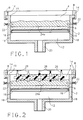
- FIG. 1 The accompanying drawings show an open-ended container 2 divided into a mould-forming and retaining chamber 4 and a gas plenum 12 by a porous, gas-permeable wall 6.
- a temporary, removable rim 14 is positioned on top of the mouth 10 of the container 2 so as to effectively increase the depth of the chamber 4 and extend it beyond the mouth 10 to permit ready formation of a mould portion which protrudes outwards from the mouth 10 of the container 2 as will be described in more detail hereinafter.
- the porous wall 6 may comprise sintered metal, ceramic frit, microporous diffuser plate/screen, or the like, and is detachably secured to an annular shelf 16 affixed to the inside of the walls 18 forming the container 2.
- a duct 20 communicates with the gas plenum 12 and is connected to sources of vacuum or pressurized gas (i.e., curing, fluidizing or discharging as appropriate) through an appropriate valving arrangement (not shown).
- Spring-biased retractable retainer pins 22 may be provided through the walls 18 to retain the mould in the chamber 4 and to ensure that it does not accidentally become dislodged when the container 2 is in the inverted position (i.e., open end down).
- the container 2 is initially oriented with its mouth 10 facing upwardly as shown in Figure 1.
- An initial layer of mould-forming particulate material 24a is preferably dispensed into the chamber 4 onto the porous wall 6.
- the particulates will preferably comprise foundry sand (e.g., silica, or zirconia,) which is coated with a known precursor of the resin binder to be formed therein to hold the particulates together.
- the precursors may comprise: a mixture of phenolic and isocyanate resins which are subsequently cross-linked by passing a catalyzing amine vapor (e.g., triethanolamine) therethrough to form a phenolic-urethane binder; a phenolic resin which is subsequently reacted with methylformate gas passed therethrough to form a phenolic-ester resin binder; or a mixture of acrylic epoxy resin, hydroperoxide and silane which is subsequently cured by passing sulphur dioxide (SO2) gas therethrough.
- Moulds made directly in the vacuum chamber 4, in accordance with the present invention need not have as much particulate or binder content as moulds made in separate operations and subsequently transferred to the casting site.
- the additional strength/durability provided by more particulates or higher binder content in moulds subjected to more handling is not required when making the moulds in-situ in the casting chamber for direct casting therein.
- Lower particulate and resin content reduces the cost of the mould-forming materials.
- lower resin content i.e., compared to commercially available mould-forming sands such as Isoset R , or Isocure R , improves flowability of the particulates and results in a more porous mould for the more effective removal of the pattern decomposition products from the moulding cavity during the casting operation.
- Commercial resin loadings may, of course, also be used.
- a gasifiable pattern 26 (e.g., polystyrene foam) is partially set into the initial particulate material layer 24a.
- the pattern 26 will preferably include a plurality of gate-forming projections 28 extending therefrom which serve to shape the ingates to the moulding cavity which is shaped by the remainder of the pattern 26.
- Appropriate means or fixtures may be employed to hold the pattern 26 in position in the chamber section 4 during subsequent operations.
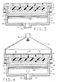
- additional particulate material 24b is dispensed into the chamber 4, the rim 14 and around the pattern 26, as best shown in Figure 3.
- the gate-forming projections 28 of the pattern 26 extend to the exposed surface 30 of the mould-forming particulate material 24b which itself is flush with the upper surface 8 of the temporary rim 14.
- the particulate-filled container is transferred to a curing station (see Figure 4) which includes a hood 32 having a screen 34, or porous material similar to that comprising wall 6, on the lower end thereof for engaging the upper surface 30 of the particulate mass 24b.
- the screen 34 is sufficiently fine as to distribute the curing gas substantially evenly throughout the particulate mass 24b during the curing operation.
- the hood 32 includes an appropriate duct 36 for introducing curing gas into the hood 32.
- a curing gas e.g., catalyst or reactive material
- a curing gas is admitted to hood 32 via duct 36 from whence it subsequently passes through the particulate mass 24b, the porous, gas-permeable wall 6, and into the plenum 12 before exhausting through the duct 20 to the atmosphere or to appropriate air-cleaning equipment (e.g., scrubbers - not shown) as may be needed.
- the curing gas may be admitted to the particulate mass 24b via the plenum 12 and wall 6 and exhausted therefrom via the hood 32.
- the screen 30 serves the additional function of preventing passage of mould-forming particulates into the hood 32 and duct 36.
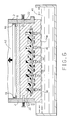
- the rim 14 is removed from the mouth 10 of the container 2 leaving a portion 38 of the mould (see Figure 5) protruding from the mouth 10 of the container 2 and adapted for immersion into a pool of metal melt.
- the container 2 is then inverted such that the protruding mould portion 38 underlies the container 2 as best shown in Figure 5.
- the protruding portion 38 of the mould is then immersed in a pool 40 of molten metal and a vacuum established in plenum 12 to draw the molten metal up into a mould cavity 42 formed by the pattern 26.
- the pattern 26 gasifies ahead of the liquid metal front and the gaseous products formed therein, resulting from the gasification of the pattern 26, are sucked out of the mould cavity 42 through the interstitial pores of the mould 24m by the vacuum in the plenum 12.
- the mould 24m is discharged from the container 2 and the cycle repeated. More specifically, the retainer pins 22, if used, are retracted and pressurized air admitted to the plenum 12 to blow the mould 24m free of the chamber 4 in container 2.
Landscapes
- Engineering & Computer Science (AREA)
- Mechanical Engineering (AREA)
- Casting Or Compression Moulding Of Plastics Or The Like (AREA)
- Casting Devices For Molds (AREA)
- Mold Materials And Core Materials (AREA)
- Moulds For Moulding Plastics Or The Like (AREA)
Applications Claiming Priority (2)
| Application Number | Priority Date | Filing Date | Title |
|---|---|---|---|
| US191468 | 1988-05-09 | ||
| US07/191,468 US4848439A (en) | 1988-05-09 | 1988-05-09 | Method of countergravity casting |
Publications (2)
| Publication Number | Publication Date |
|---|---|
| EP0341815A2 true EP0341815A2 (de) | 1989-11-15 |
| EP0341815A3 EP0341815A3 (de) | 1990-12-19 |
Family
ID=22705617
Family Applications (1)
| Application Number | Title | Priority Date | Filing Date |
|---|---|---|---|
| EP19890302738 Withdrawn EP0341815A3 (de) | 1988-05-09 | 1989-03-20 | Verfahren zum Gegen-Schwerkraft-Giessen |
Country Status (4)
| Country | Link |
|---|---|
| US (1) | US4848439A (de) |
| EP (1) | EP0341815A3 (de) |
| JP (1) | JPH01306063A (de) |
| BR (1) | BR8902088A (de) |
Families Citing this family (9)
| Publication number | Priority date | Publication date | Assignee | Title |
|---|---|---|---|---|
| US4957153A (en) * | 1989-05-02 | 1990-09-18 | General Motors Corporation | Countergravity casting apparatus and method |
| GB8915826D0 (en) * | 1989-07-11 | 1989-08-31 | Auto Alloys Foundries Limited | Casting of metals |
| US4971131A (en) * | 1989-08-28 | 1990-11-20 | General Motors Corporation | Countergravity casting using particulate filled vacuum chambers |
| US5062467A (en) * | 1991-05-10 | 1991-11-05 | General Motors Corporation | Vacuum countergravity casting apparatus and method |
| US5062466A (en) * | 1991-05-10 | 1991-11-05 | General Motors Corporation | Countergravity casting apparatus and method |
| US5271451A (en) * | 1992-09-01 | 1993-12-21 | General Motors Corporation | Metal casting using a mold having attached risers |
| US6684934B1 (en) | 2000-05-24 | 2004-02-03 | Hitchiner Manufacturing Co., Inc. | Countergravity casting method and apparatus |
| DE112006000461T5 (de) * | 2005-02-22 | 2008-03-13 | Milwaukee School Of Engineering, Milwaukee | Gießverfahren |
| WO2012092244A2 (en) | 2010-12-29 | 2012-07-05 | Android Industries Llc | Working tank with vacuum assist |
Family Cites Families (8)
| Publication number | Priority date | Publication date | Assignee | Title |
|---|---|---|---|---|
| US3780787A (en) * | 1971-06-17 | 1973-12-25 | J Rasmussen | Method of vacuum investment casting |
| DE2519463A1 (de) * | 1975-05-02 | 1976-11-11 | Gruenzweig Hartmann Glasfaser | Giessform und verfahren zur herstellung von gusstuecken |
| US4340108A (en) * | 1979-09-12 | 1982-07-20 | Hitchiner Manufacturing Co., Inc. | Method of casting metal in sand mold using reduced pressure |
| JPS5855149A (ja) * | 1981-09-28 | 1983-04-01 | Sintokogio Ltd | ガス硬化式主型造型装置 |
| FR2559407B1 (fr) * | 1984-02-15 | 1986-09-05 | Pont A Mousson | Procede de moulage en fonderie et moule pour la coulee de precision sous basse pression, avec modele gazeifiable et moule en sable sans liant |
| GB2159445B (en) * | 1984-06-02 | 1988-07-06 | Cosworth Res & Dev Ltd | Casting of metal articles |
| US4632171A (en) * | 1984-09-26 | 1986-12-30 | General Motors Corporation | Counter-gravity casting mold |
| US4754798A (en) * | 1987-09-15 | 1988-07-05 | Metal Casting Technology, Inc. | Casting metal in a flowable firmly set sand mold cavity |
-
1988
- 1988-05-09 US US07/191,468 patent/US4848439A/en not_active Expired - Fee Related
-
1989
- 1989-03-20 EP EP19890302738 patent/EP0341815A3/de not_active Withdrawn
- 1989-04-13 JP JP1094280A patent/JPH01306063A/ja active Granted
- 1989-05-04 BR BR898902088A patent/BR8902088A/pt unknown
Also Published As
| Publication number | Publication date |
|---|---|
| EP0341815A3 (de) | 1990-12-19 |
| JPH0260430B2 (de) | 1990-12-17 |
| US4848439A (en) | 1989-07-18 |
| JPH01306063A (ja) | 1989-12-11 |
| BR8902088A (pt) | 1989-12-05 |
Similar Documents
| Publication | Publication Date | Title |
|---|---|---|
| US3964534A (en) | Casting method with a vacuum bonded dry sand core | |
| EP0341486B1 (de) | Gegen-Schwerkraft-Giessverfahren und Einrichtung bei Verwendung zerstörbarer Modelle suspendiert in einer inhärenten labilen Menge des Partikel-Formmaterials | |
| US4693292A (en) | Casting of metal articles | |
| CN101462160B (zh) | 树脂砂实型铸造工艺 | |
| AU594734B2 (en) | Manufacture of light metal castings | |
| EP0341815A2 (de) | Verfahren zum Gegen-Schwerkraft-Giessen | |
| US4993473A (en) | Differential pressure, countergravity casting using mold ingate chills | |
| EP0395852B1 (de) | Einrichtung und Verfahren zum Giessen gegen die Schwerkraft | |
| EP0225040B1 (de) | Giessform und Kernzusammensetzung für das Unterdruckgiessverfahren | |
| EP0585598B1 (de) | Metallguss unter Verwendung einer mit Speisern versehenen Form | |
| US6845810B2 (en) | Lost-foam casting apparatus for improved recycling of sprue-metal | |
| US4971131A (en) | Countergravity casting using particulate filled vacuum chambers | |
| JPH02104461A (ja) | 薄肉部品を注型するための真空反重力式注型装置及び方法 | |
| US5062467A (en) | Vacuum countergravity casting apparatus and method | |
| JPH01313130A (ja) | 消失模型鋳造方法 | |
| EP0489509A2 (de) | Verfahren zur Herstellung von Kernen und Gussformen | |
| US5388630A (en) | Method of manufacturing core and mold | |
| CA1338547C (en) | Process for producing mouldings | |
| JPS59166347A (ja) | 充填鋳造法における造型方法 | |
| JPS62207530A (ja) | 鋳造法 | |
| GB2153274A (en) | Process and apparatus for lost foam casting with bonded sand core | |
| SU1731407A1 (ru) | Способ лить по газифицируемым модел м | |
| GB2234926A (en) | Casting into a gas-permeable mould | |
| JPS62179849A (ja) | 鋳造法 | |
| JPH0724932B2 (ja) | 有機自硬性鋳型を用いた鋳造方法 |
Legal Events
| Date | Code | Title | Description |
|---|---|---|---|
| PUAI | Public reference made under article 153(3) epc to a published international application that has entered the european phase |
Free format text: ORIGINAL CODE: 0009012 |
|
| AK | Designated contracting states |
Kind code of ref document: A2 Designated state(s): DE FR GB IT |
|
| PUAL | Search report despatched |
Free format text: ORIGINAL CODE: 0009013 |
|
| AK | Designated contracting states |
Kind code of ref document: A3 Designated state(s): DE FR GB IT |
|
| 17P | Request for examination filed |
Effective date: 19910108 |
|
| 17Q | First examination report despatched |
Effective date: 19920401 |
|
| STAA | Information on the status of an ep patent application or granted ep patent |
Free format text: STATUS: THE APPLICATION HAS BEEN WITHDRAWN |
|
| 18W | Application withdrawn |
Withdrawal date: 19920513 |