EP0341675A2 - Alcohol sensor - Google Patents
Alcohol sensor Download PDFInfo
- Publication number
- EP0341675A2 EP0341675A2 EP89108345A EP89108345A EP0341675A2 EP 0341675 A2 EP0341675 A2 EP 0341675A2 EP 89108345 A EP89108345 A EP 89108345A EP 89108345 A EP89108345 A EP 89108345A EP 0341675 A2 EP0341675 A2 EP 0341675A2
- Authority
- EP
- European Patent Office
- Prior art keywords
- electrostatic capacity
- alcohol
- electric insulating
- fuel
- alcohol sensor
- Prior art date
- Legal status (The legal status is an assumption and is not a legal conclusion. Google has not performed a legal analysis and makes no representation as to the accuracy of the status listed.)
- Granted
Links
Images


Classifications
-
- G—PHYSICS
- G01—MEASURING; TESTING
- G01N—INVESTIGATING OR ANALYSING MATERIALS BY DETERMINING THEIR CHEMICAL OR PHYSICAL PROPERTIES
- G01N27/00—Investigating or analysing materials by the use of electric, electrochemical, or magnetic means
- G01N27/60—Investigating or analysing materials by the use of electric, electrochemical, or magnetic means by investigating electrostatic variables, e.g. electrographic flaw testing
-
- G—PHYSICS
- G01—MEASURING; TESTING
- G01N—INVESTIGATING OR ANALYSING MATERIALS BY DETERMINING THEIR CHEMICAL OR PHYSICAL PROPERTIES
- G01N27/00—Investigating or analysing materials by the use of electric, electrochemical, or magnetic means
- G01N27/02—Investigating or analysing materials by the use of electric, electrochemical, or magnetic means by investigating impedance
- G01N27/22—Investigating or analysing materials by the use of electric, electrochemical, or magnetic means by investigating impedance by investigating capacitance
- G01N27/221—Investigating or analysing materials by the use of electric, electrochemical, or magnetic means by investigating impedance by investigating capacitance by investigating the dielectric properties
-
- G—PHYSICS
- G01—MEASURING; TESTING
- G01N—INVESTIGATING OR ANALYSING MATERIALS BY DETERMINING THEIR CHEMICAL OR PHYSICAL PROPERTIES
- G01N33/00—Investigating or analysing materials by specific methods not covered by groups G01N1/00 - G01N31/00
- G01N33/26—Oils; Viscous liquids; Paints; Inks
- G01N33/28—Oils, i.e. hydrocarbon liquids
- G01N33/2835—Specific substances contained in the oils or fuels
- G01N33/2852—Alcohol in fuels
Definitions
- the present invention relates to an alcohol sensor of the electrostatic capacity type for detecting a mixing ratio of alcohol in fuel.
- Alcohol sensors conventionally adopted for measuring a mixing ratio of alcohol in fuel are those which make use of the fact that an electrostatic capacity formed between a pair or a plurality of pairs of electrode plates disposed in a fuel passage has a proportional relationship to such alcohol mixing ratio.
- An exemplary one of such alcohol sensors is disclosed, for example, in Japanese Patent Laid-open No. 62-18004.
- a change in electrostatic capacity is converted into a change in oscillation frequency of a CR oscillator, and an alcohol mixing ratio is detected in accordance with a relationship thereof to the oscillation frequency.
- the electrostatic capacity measuring CR oscillating circuit shown includes a resistor 8 and a capacitor 9 formed from a pair or a plurality of pairs of electrode plates disposed in a fuel passage.
- the opposite ends of the capacitor 9 are connected at a pair of points a and b to a timer IC (integrated circuit) 7 by way of a pair of lead wires 5a and 5b, respectively.
- a resistor 8 is connected to the capacitor 9 at the point a and also connected at the opposite ends thereof to the timer IC 7.
- the timer IC 7 includes an oscillating element not shown therein and produces oscillations which have a frequency determined by a time constant RC defined by a capacity of the capacitor 9 and a resistance R of the resistor 8.
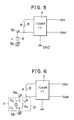
- the capacitor 9 formed between the electrodes is represented as a parallel circuit of a capacitor having an electrostatic capacity Cx and a resistor having a loss Rx as shown in Fig.6.
- the capacitor C may be considered in such a simplified form as shown in Fig.5.
- ⁇ is a dielectric constant of fuel
- S an area of opposing faces of the electrode plates
- d a distance between the electrodes
- ⁇ a volume resistivity
- the conventional electrostatic capacity measuring CR oscillating circuit has such a construction as described above, if the volume resistivity of fuel decreases due to an increase in concentration of alcohol in gasoline or due to an increase in percentage of water content in gasoline, then the loss Rx of the capacitor 9 decreases. Accordingly, there causes a problem that oscillation of the electrostatic capacity measuring CR oscillating circuit may possibly be stopped.
- an alcohol sensor having an electrostatic capacity detecting section disposed in a fuel passage to measure an electrostatic capacity thereby for detecting a mixing ratio of alcohol in fuel is constituted in such a manner that a surface of each of electrode layers which form the electrostatic capacity detecting section is covered with an electric insulating layer.
- the alcohol sensor according to the present invention detects a mixing ratio of alcohol in fuel by detecting an electrostatic capacity of a capacitor which is formed by alcohol-mixed fuel filled between the electrode layers covered with electric insulating layers.
- an electrostatic capacity corresponding to a mixing ratio of alcohol can be always detected without relying upon a volume resistivity of fuel and can be converted into an oscillation frequency with a simple circuit.
- FIG.1 there is shown an alcohol sensor according to a preferred embodiment of the present invention. It is to be noted that, in Fig.1 and also in Figs.2 to 4, like parts or elements are denoted by the same reference characters as Figs. 5 and 6 described hereinabove.
- the alcohol sensor shown includes a plurality of, three in the embodiment, electrode layers 2 (shadowed portions) disposed in a predetermined spaced relationship in a fuel passage 1 in which fuel containing alcohol therein passes.
- a pair of lead wires 5a and 5b made of a conductive rigid material are connected to the electrode layers 2 in such a manner that they are all mechanically coupled to the electrode layers 2 but are electrically connected to different alternate ones of the electrode layers 2, that is, the lead wire 5a is electrically connected to the central one of the electrode layers 2 in Fig.1 while the other lead wire 5b is electrically connected to the other two electrode layers 2 on the opposite sides of the central layer 2.
- Each of the electrode layers 2 has a perforation formed therein, and an electric insulating piece 4 is securely fitted in the perforation.
- the lead wires 5a and 5b extend through and are secured to the electric insulating pieces 4 by way of which the lead wires 5a and 5b are mechanically coupled but not electrically connectd to the electrode layers 2 while assuring electric insulation between the electrode layers 2 and the lead wires 5a and 5b.
- the lead wires 5a and 5b are connected at a pair of points a and b to an electrostatic capacity measuring CR oscillating circuit shown in Fig.2.
- the lead wires 5a and 5b thus support the electrode layers 2 in position thereon in the fuel passage 1 due to their rigidity.
- All surfaces of the elements of the alcohol sensor described above are covered with an electric insulating layer 3 in such a manner that only the electric insulating layer 3 is exposed to fuel in the fuel passage 1.
- a capacitor 9 shown in Fig.2 for detecting alcohol is thus formed with portions of the electric insulating layer 3 located between the individual electrode layers 2.
- FIG.2 there is shown an electrostatic capacity measuring CR oscillating circuit which employs the alcohol sensor of Fig.1.
- the electrostatic capacity measuring CR oscillating circuit shown has a substantially similar construction to that of the conventional electrostatic capacity measuring CR oscillating circuit shown in Fig.5 but is only different in detailed construction of the capacitor 9 serving as an alcohol sensor.
- the opposite ends of the capacitor 9 are connected at a pair of points a and b to a timer IC (integrated circuit) 7 by way of a pair of lead wires 5a and 5b, respectively.
- a resistor 8 is connected to the capacitor 9 at the point a and also connected at the opposite ends thereof to the timer IC 7 which includes an oscillating element therein (not shown).
- a capacitor 9 formed from a pair of electrode plates 10 opposing surfaces of which are covered with electric insulating layers 3 has an electrostatic capacity C which is equivalent to that of a series circuit of a capacitor having an electrostatic capacity Cx formed by fuel filled between the electrode plates 10 and another capacitor having an electrostatic capacity Co formed by the electric insulating layers 3.
- the inter-electrode distance do of the electrostatic capacity Co that is, the thickness do of each electric insulating layer 3
- the inter-electrode distance dx of the electrostatic capacity Cx should be set sufficiently smaller than the inter-electrode distance dx of the electrostatic capacity Cx, or else a material of a high dielectric constant should be employed for the electric insulating layers 3 so as to assure a high dielectric constant ⁇ .
- the alcohol sensor can always convert a change in characteristics of fuel into a change oscillation frequency.
- the alcohol sensor shown can be produced by such a method that an electric insulating material is coated on a surface of a metal plate to be used as an electrode layer 2 by a physico-chemical means such as painting, adhesion, welding, evaporation and dipping to form an electric insulating layer 3 and then such metal plates 2 are assembled into such an alcohol sensor as shown in Fig.1.
- the alcohol sensor may be produced otherwise by another method that an assembly of such electrode layers 2 as shown in Fig.1 is first produced and then an electric insulating material is coated on all of electrostatic capacity detecting sections of the assembly by such physico-chemical means as listed above to form such an electric insulating layer or layers 3 as seen in Fig.1
- the surfaces of the electrostatic capacity detecting sections to be exposed in the fuel passage 1 are entirely covered with the electric insulating layer or layers 3, they may otherwise be covered partially or in a different manner with the electric insulating layer or layers 3.
- Fig.4 an alcohol sensor according to a second embodiment of the present invention is shown which has such a modified construction as described just above.
- the alcohol sensor shown includes a plurality of, three in the present embodiment, base plates 6 each having a pair of electrode layers 2 formed on the opposite surfaces thereof by printing in such a manner as to partially expose the opposite the opposite surfaces of the base plates 6.
- a pair of lead wires 5a and 5b are mechanically coupled to all of the base plates 6 and electrically connected to the electrode layers 2 on different alternate ones of the base plates 6 as seen in Fig.4. Surfaces of each of the base plates 6 and the electrode layers 2 on each base plate 6 are covered with an electric insulating layer 3 so that neither of the base plates 6 nor the electrode layers 2 may be exposed.
- printing of an electric insulating material may be employed in addition to such physico-chemical means as described above in order to form such electric insulating layers 2. such printing technique will enable simplification and reduction in working steps for production of an alcohol sensor and is advantageous in cost.
- the number of such capacitors may be selected suitably by a user depending upon an area of and a distance between the electrodes, a dielectric constant ⁇ of the electric insulating layers 3 and the oscillation frequency of the electrostatic capacity measuring CR oscillating circuit.
Landscapes
- Chemical & Material Sciences (AREA)
- Health & Medical Sciences (AREA)
- Life Sciences & Earth Sciences (AREA)
- General Health & Medical Sciences (AREA)
- Immunology (AREA)
- Pathology (AREA)
- Analytical Chemistry (AREA)
- Biochemistry (AREA)
- Chemical Kinetics & Catalysis (AREA)
- General Physics & Mathematics (AREA)
- Physics & Mathematics (AREA)
- Electrochemistry (AREA)
- Engineering & Computer Science (AREA)
- General Chemical & Material Sciences (AREA)
- Oil, Petroleum & Natural Gas (AREA)
- Food Science & Technology (AREA)
- Medicinal Chemistry (AREA)
- Investigating Or Analyzing Materials By The Use Of Electric Means (AREA)
Abstract
Description
- The present invention relates to an alcohol sensor of the electrostatic capacity type for detecting a mixing ratio of alcohol in fuel.
- Alcohol sensors conventionally adopted for measuring a mixing ratio of alcohol in fuel are those which make use of the fact that an electrostatic capacity formed between a pair or a plurality of pairs of electrode plates disposed in a fuel passage has a proportional relationship to such alcohol mixing ratio. An exemplary one of such alcohol sensors is disclosed, for example, in Japanese Patent Laid-open No. 62-18004.
- In such an alcohol sensor of the electrostatic capacity type as described above, a change in electrostatic capacity is converted into a change in oscillation frequency of a CR oscillator, and an alcohol mixing ratio is detected in accordance with a relationship thereof to the oscillation frequency.
- Such a conventional CR oscillating circuit for measurement of an electrostatic capacity is illustratively shown in Fig.5. Referring to Fig.5, the electrostatic capacity measuring CR oscillating circuit shown includes a
resistor 8 and a capacitor 9 formed from a pair or a plurality of pairs of electrode plates disposed in a fuel passage. The opposite ends of the capacitor 9 are connected at a pair of points a and b to a timer IC (integrated circuit) 7 by way of a pair oflead wires resistor 8 is connected to the capacitor 9 at the point a and also connected at the opposite ends thereof to thetimer IC 7. Thetimer IC 7 includes an oscillating element not shown therein and produces oscillations which have a frequency determined by a time constant RC defined by a capacity of the capacitor 9 and a resistance R of theresistor 8. - Actually, the capacitor 9 formed between the electrodes is represented as a parallel circuit of a capacitor having an electrostatic capacity Cx and a resistor having a loss Rx as shown in Fig.6. However, where the loss Rx is so high that it does not have a significant influence on the time constant RC mentioned above, the capacitor C may be considered in such a simplified form as shown in Fig.5. It is to be noted that the electrostatic capacity Cx and the loss Rx shown in Fig.6 are represented by the following equations:
Cx = ε * S/d (1)
Rx = ρ * S/d (2) - Here, ε is a dielectric constant of fuel, S an area of opposing faces of the electrode plates, d a distance between the electrodes, and ρ a volume resistivity.
- Since the conventional electrostatic capacity measuring CR oscillating circuit has such a construction as described above, if the volume resistivity of fuel decreases due to an increase in concentration of alcohol in gasoline or due to an increase in percentage of water content in gasoline, then the loss Rx of the capacitor 9 decreases. Accordingly, there causes a problem that oscillation of the electrostatic capacity measuring CR oscillating circuit may possibly be stopped.
- The reason for this seems to be as follows. In particular, electric current I flowing through the capacitor 9 is divided as Ic and Ir into the electrostatic capacity Cx and the loss Rx, but if the volume resistivity of fuel decreases so that the loss Rx decreases, then the electric current Ir becomes extremely great comparing with the electric current Ic so that the electrostatic capacity Cx finally loses its function. It can be considered that oscillation of the CR oscillator is stopped by this reason.
- It is an object of the present invention to provide an alcohol sensor which can always measure a mixing ratio of alcohol in fuel even if the volume resistivity of the fuel decreases due to an increase in concentration of alcohol in gasoline or due to an increase in percentage of water content in gasoline.
- In order to attain the object, according to the present invention, an alcohol sensor having an electrostatic capacity detecting section disposed in a fuel passage to measure an electrostatic capacity thereby for detecting a mixing ratio of alcohol in fuel is constituted in such a manner that a surface of each of electrode layers which form the electrostatic capacity detecting section is covered with an electric insulating layer.
- The alcohol sensor according to the present invention detects a mixing ratio of alcohol in fuel by detecting an electrostatic capacity of a capacitor which is formed by alcohol-mixed fuel filled between the electrode layers covered with electric insulating layers.
- With the alcohol sensor, an electrostatic capacity corresponding to a mixing ratio of alcohol can be always detected without relying upon a volume resistivity of fuel and can be converted into an oscillation frequency with a simple circuit.
- The above and other objects, features and advantages of the present invention will become apparent from the following description and the appended claims, taken in conjunction with the accompanying drawings.
-
- Fig.1 is a sectional view of an alcohol sensor showing a preferred embodiment of the present invention;
- Fig.2 is a circuit diagram of an electrostatic capacity measuring CR oscillating circuit which employs the alcohol sensor of Fig.1 therein;
- Fig.3 is a schematic view illustrating a principle of detection of a mixing ratio of alcohol in fuel by means of a capacitor of the electrostatic capacity measuring CR oscillating circuit of Fig.2;
- Fig.4 is a view similar to Fig.1 but showing another alcohol sensor according to a second embodiment of the present invention;
- Fig.5 is a view similar to Fig.2 but showing a conventional electrostatic capacity measuring CR oscillating circuit; and
- Fig.6 is a similar view but illustrating a reason for the fact that oscillation is stopped when the loss of a capacitor in the electrostatic capacity measuring CR oscillating circuit of Fig.5 decreases.
- Referring first to Fig.1, there is shown an alcohol sensor according to a preferred embodiment of the present invention. It is to be noted that, in Fig.1 and also in Figs.2 to 4, like parts or elements are denoted by the same reference characters as Figs. 5 and 6 described hereinabove.
- The alcohol sensor shown includes a plurality of, three in the embodiment, electrode layers 2 (shadowed portions) disposed in a predetermined spaced relationship in a
fuel passage 1 in which fuel containing alcohol therein passes. A pair oflead wires electrode layers 2 in such a manner that they are all mechanically coupled to theelectrode layers 2 but are electrically connected to different alternate ones of theelectrode layers 2, that is, thelead wire 5a is electrically connected to the central one of theelectrode layers 2 in Fig.1 while theother lead wire 5b is electrically connected to the other twoelectrode layers 2 on the opposite sides of thecentral layer 2. Each of theelectrode layers 2 has a perforation formed therein, and an electricinsulating piece 4 is securely fitted in the perforation. Thelead wires electric insulating pieces 4 by way of which thelead wires electrode layers 2 while assuring electric insulation between theelectrode layers 2 and thelead wires lead wires lead wires electrode layers 2 in position thereon in thefuel passage 1 due to their rigidity. - All surfaces of the elements of the alcohol sensor described above are covered with an
electric insulating layer 3 in such a manner that only theelectric insulating layer 3 is exposed to fuel in thefuel passage 1. A capacitor 9 shown in Fig.2 for detecting alcohol is thus formed with portions of the electricinsulating layer 3 located between theindividual electrode layers 2. - Referring now to Fig.2, there is shown an electrostatic capacity measuring CR oscillating circuit which employs the alcohol sensor of Fig.1. The electrostatic capacity measuring CR oscillating circuit shown has a substantially similar construction to that of the conventional electrostatic capacity measuring CR oscillating circuit shown in Fig.5 but is only different in detailed construction of the capacitor 9 serving as an alcohol sensor. In particular, the opposite ends of the capacitor 9 are connected at a pair of points a and b to a timer IC (integrated circuit) 7 by way of a pair of
lead wires resistor 8 is connected to the capacitor 9 at the point a and also connected at the opposite ends thereof to thetimer IC 7 which includes an oscillating element therein (not shown). - Referring now to Fig.3, there is illustrated a principle of the capacitor 9 shown in Fig.2. In particular, a capacitor 9 formed from a pair of
electrode plates 10 opposing surfaces of which are covered with electricinsulating layers 3 has an electrostatic capacity C which is equivalent to that of a series circuit of a capacitor having an electrostatic capacity Cx formed by fuel filled between theelectrode plates 10 and another capacitor having an electrostatic capacity Co formed by the electricinsulating layers 3. In this instance, the composite electrostatic capacity Ct of the electrostatic capacity measuring CR oscillating circuit is represented by the following equation.
Ct = 1(2/Co + 1/Cx) (3) - Since the oscillation frequency of the CR oscillating circuit of Fig.2 is determined in accordance with a time constant defined by a resistance R of the
resistor 8 and the composite electrostatic capacity Ct of the capacitor 9, if the electrostatic capacity Co is made as high as possible, Ct = Cx is almost reached as apparent from the equation (3). In this instance, no influence of the electricinsulating layers 3 is provided on the composite electrostatic capacity Ct of the capacitor 9. - Accordingly, a relationship Cx > Co should be established in the equation (3) above. To this end, the inter-electrode distance do of the electrostatic capacity Co, that is, the thickness do of each electric
insulating layer 3, should be set sufficiently smaller than the inter-electrode distance dx of the electrostatic capacity Cx, or else a material of a high dielectric constant should be employed for the electricinsulating layers 3 so as to assure a high dielectric constant ε. - In this instance, even if fuel has a low volume resistivity, oscillation of the electrostatic capacity measuring CR oscillating circuit is not stopped because charging and discharging occur at the electrostatic capacity Ct due to the fact that charging and discharging occur at the electrostatic capacity Co of the capacitor 9. In other words, where the
electrode plates 10 are covered with the electricinsulating layers 3, the alcohol sensor can always convert a change in characteristics of fuel into a change oscillation frequency. - Referring back to Fig.1, the alcohol sensor shown can be produced by such a method that an electric insulating material is coated on a surface of a metal plate to be used as an
electrode layer 2 by a physico-chemical means such as painting, adhesion, welding, evaporation and dipping to form anelectric insulating layer 3 and thensuch metal plates 2 are assembled into such an alcohol sensor as shown in Fig.1. The alcohol sensor may be produced otherwise by another method that an assembly ofsuch electrode layers 2 as shown in Fig.1 is first produced and then an electric insulating material is coated on all of electrostatic capacity detecting sections of the assembly by such physico-chemical means as listed above to form such an electric insulating layer orlayers 3 as seen in Fig.1 - While in the alcohol sensor of the embodiment shown in Fig.1 the surfaces of the electrostatic capacity detecting sections to be exposed in the
fuel passage 1 are entirely covered with the electric insulating layer orlayers 3, they may otherwise be covered partially or in a different manner with the electric insulating layer orlayers 3. Referring now to Fig.4, an alcohol sensor according to a second embodiment of the present invention is shown which has such a modified construction as described just above. In particular, the alcohol sensor shown includes a plurality of, three in the present embodiment,base plates 6 each having a pair ofelectrode layers 2 formed on the opposite surfaces thereof by printing in such a manner as to partially expose the opposite the opposite surfaces of thebase plates 6. A pair oflead wires base plates 6 and electrically connected to theelectrode layers 2 on different alternate ones of thebase plates 6 as seen in Fig.4. Surfaces of each of thebase plates 6 and the electrode layers 2 on eachbase plate 6 are covered with an electric insulatinglayer 3 so that neither of thebase plates 6 nor the electrode layers 2 may be exposed. In this arrangement, printing of an electric insulating material may be employed in addition to such physico-chemical means as described above in order to form such electric insulatinglayers 2. such printing technique will enable simplification and reduction in working steps for production of an alcohol sensor and is advantageous in cost. - It is to be noted that, while in the embodiments of Figs.1 and 4 the two capacitors are connected in parallel, the number of such capacitors may be selected suitably by a user depending upon an area of and a distance between the electrodes, a dielectric constant ε of the electric insulating
layers 3 and the oscillation frequency of the electrostatic capacity measuring CR oscillating circuit. - Further, only if a surface of an electrostatic capacity detecting section is covered with an electric insulating layer, similar effects can be anticipated without depending upon the configurations of the embodiments and the coating means. Where a sensor is accommodated in a case, if the case itself is covered with an electric insulating layer, then the influence of a resistance provided between the case and electrodes can be ignored by the same reason as in the embodiments described above, and accordingly, improvement in accuracy can be obtained.
- Having now fully described the invention, it will be apparent to one of ordinary skill in the art that many changes and modifications can be made thereto without departing from the spirit and scope of the invention as set forth herein.
Claims (5)
an electrostatic capacity detecting section (CR) disposed in said fuel passage (1) to measure an electric capacity of the fuel fed therethrough; and
a plurality of electrode layers (2) that form said electrostatic capacity detecting section (CR); wherein a surface of each of said electrode layers (2) is covered with an electric insulating layer (3).
Applications Claiming Priority (2)
| Application Number | Priority Date | Filing Date | Title |
|---|---|---|---|
| JP1988063780U JPH01165457U (en) | 1988-05-12 | 1988-05-12 | |
| JP63780/88U | 1988-05-12 |
Publications (3)
| Publication Number | Publication Date |
|---|---|
| EP0341675A2 true EP0341675A2 (en) | 1989-11-15 |
| EP0341675A3 EP0341675A3 (en) | 1990-07-04 |
| EP0341675B1 EP0341675B1 (en) | 1994-08-03 |
Family
ID=13239236
Family Applications (1)
| Application Number | Title | Priority Date | Filing Date |
|---|---|---|---|
| EP89108345A Expired - Lifetime EP0341675B1 (en) | 1988-05-12 | 1989-05-09 | Alcohol sensor |
Country Status (4)
| Country | Link |
|---|---|
| EP (1) | EP0341675B1 (en) |
| JP (1) | JPH01165457U (en) |
| KR (1) | KR910004509Y1 (en) |
| DE (1) | DE68917199T2 (en) |
Cited By (19)
| Publication number | Priority date | Publication date | Assignee | Title |
|---|---|---|---|---|
| US5196801A (en) * | 1988-12-19 | 1993-03-23 | Calsonic Corporation | Capacitance-type fuel sensor for sensing methanol in methanol-mixed fuel |
| EP0674171A1 (en) * | 1994-03-24 | 1995-09-27 | PIMA Sensors, Inc. | Gas sensor and sensing device |
| EP0901013A1 (en) * | 1997-09-02 | 1999-03-10 | Goss Graphic Systems, Inc. | Water content metering apparatus |
| WO2000034767A1 (en) * | 1998-12-04 | 2000-06-15 | Sargent John S | Volume charge density measuring system |
| US6586949B1 (en) | 1999-12-03 | 2003-07-01 | John S. Sargent | Volume charge density measuring system |
| US6586950B1 (en) | 1998-12-04 | 2003-07-01 | John S. Sargent | Volume charge density measuring system |
| US6716119B1 (en) | 2002-11-06 | 2004-04-06 | Pro Performance Sports, Inc. | Sports ball striking training device |
| EP1610119A1 (en) * | 2004-06-24 | 2005-12-28 | Ngk Spark Plug Co., Ltd. | Capacity type liquid state detecting sensor |
| WO2008003365A3 (en) * | 2006-07-06 | 2008-04-24 | Bartec Gmbh | Capacitive measuring device for detecting foreign substances in a liquid |
| WO2008106989A1 (en) * | 2007-03-02 | 2008-09-12 | Bartec Gmbh | Device and method for detecting a volume while receiving and/or discharging a fluid having a gas portion |
| WO2016137343A1 (en) * | 2015-02-23 | 2016-09-01 | Alsemix Sp. Z O.O. | Method for determination of ethanol content in fuel for internal combustion engines |
| EP3355051A4 (en) * | 2016-04-27 | 2018-08-22 | KYB Corporation | Sensor and method for producing sensor |
| US11467094B2 (en) | 2017-05-17 | 2022-10-11 | University Of Florida Research Foundation, Inc. | Methods and sensors for detection |
| US11480527B2 (en) | 2017-12-20 | 2022-10-25 | University Of Florida Research Foundation, Inc. | Methods and sensors for detection |
| US11705527B2 (en) | 2017-12-21 | 2023-07-18 | University Of Florida Research Foundation, Inc. | Substrates having a broadband antireflection layer and methods of forming a broadband antireflection layer |
| US11795281B2 (en) | 2016-08-15 | 2023-10-24 | University Of Florida Research Foundation, Inc. | Methods and compositions relating to tunable nanoporous coatings |
| US11819277B2 (en) | 2018-06-20 | 2023-11-21 | University Of Florida Research Foundation, Inc. | Intraocular pressure sensing material, devices, and uses thereof |
| US12248123B2 (en) | 2017-12-20 | 2025-03-11 | University Of Florida Research Foundation, Inc. | Methods of forming an antireflective layer on a complex substrate and complex substrates having the antireflective layer |
| US12258470B2 (en) | 2018-02-13 | 2025-03-25 | University Of Florida Research Foundation, Inc. | Chromogenic materials, methods of making chromogenic materials, and methods of use |
Family Cites Families (5)
| Publication number | Priority date | Publication date | Assignee | Title |
|---|---|---|---|---|
| DE925621C (en) * | 1953-06-14 | 1955-03-24 | Otto Dr Velten | Method and device for automatic display of the dew point |
| GB1570039A (en) * | 1977-02-22 | 1980-06-25 | Auburn Int | Measurement of phase fractions in flowing fluid |
| GB2149117A (en) * | 1983-11-04 | 1985-06-05 | Anderson Strathclyde Plc | Detection of water in oil |
| US4757252A (en) * | 1985-10-25 | 1988-07-12 | Drexelbrook Controls, Inc. | Probe system for measuring the condition of materials |
| DE8609566U1 (en) * | 1986-04-09 | 1987-04-16 | Testoterm Meßtechnik GmbH & Co, 7825 Lenzkirch | Capacitive probe for measuring the liquid content of mixtures |
-
1988
- 1988-05-12 JP JP1988063780U patent/JPH01165457U/ja active Pending
-
1989
- 1989-04-13 KR KR2019890004560U patent/KR910004509Y1/en not_active Expired
- 1989-05-09 EP EP89108345A patent/EP0341675B1/en not_active Expired - Lifetime
- 1989-05-09 DE DE68917199T patent/DE68917199T2/en not_active Expired - Fee Related
Cited By (28)
| Publication number | Priority date | Publication date | Assignee | Title |
|---|---|---|---|---|
| US5196801A (en) * | 1988-12-19 | 1993-03-23 | Calsonic Corporation | Capacitance-type fuel sensor for sensing methanol in methanol-mixed fuel |
| EP0674171A1 (en) * | 1994-03-24 | 1995-09-27 | PIMA Sensors, Inc. | Gas sensor and sensing device |
| US5522980A (en) * | 1994-03-24 | 1996-06-04 | Pima Sensors, Inc. | Gas sensor and sensing device |
| US6169407B1 (en) | 1997-09-02 | 2001-01-02 | Goss Graphics Systems | Water content metering apparatus |
| WO1999012024A1 (en) * | 1997-09-02 | 1999-03-11 | Goss Graphic Systems, Inc. | Water content metering apparatus |
| EP0901013A1 (en) * | 1997-09-02 | 1999-03-10 | Goss Graphic Systems, Inc. | Water content metering apparatus |
| WO2000034767A1 (en) * | 1998-12-04 | 2000-06-15 | Sargent John S | Volume charge density measuring system |
| US6586950B1 (en) | 1998-12-04 | 2003-07-01 | John S. Sargent | Volume charge density measuring system |
| US6586949B1 (en) | 1999-12-03 | 2003-07-01 | John S. Sargent | Volume charge density measuring system |
| US6716119B1 (en) | 2002-11-06 | 2004-04-06 | Pro Performance Sports, Inc. | Sports ball striking training device |
| EP1610119A1 (en) * | 2004-06-24 | 2005-12-28 | Ngk Spark Plug Co., Ltd. | Capacity type liquid state detecting sensor |
| US7337662B2 (en) | 2004-06-24 | 2008-03-04 | Ngk Spark Plug Co., Ltd. | Electrostatic capacity type liquid state detecting sensor |
| CN100399000C (en) * | 2004-06-24 | 2008-07-02 | 日本特殊陶业株式会社 | Electrostatic capacity type liquid state detecting sensor |
| WO2008003365A3 (en) * | 2006-07-06 | 2008-04-24 | Bartec Gmbh | Capacitive measuring device for detecting foreign substances in a liquid |
| WO2008106989A1 (en) * | 2007-03-02 | 2008-09-12 | Bartec Gmbh | Device and method for detecting a volume while receiving and/or discharging a fluid having a gas portion |
| US8056425B2 (en) | 2007-03-02 | 2011-11-15 | Bartec Benke Gmbh | Device and method for detecting a volume while receiving and/or discharging a fluid having a gas portion |
| WO2016137343A1 (en) * | 2015-02-23 | 2016-09-01 | Alsemix Sp. Z O.O. | Method for determination of ethanol content in fuel for internal combustion engines |
| EP3355051A4 (en) * | 2016-04-27 | 2018-08-22 | KYB Corporation | Sensor and method for producing sensor |
| US11795281B2 (en) | 2016-08-15 | 2023-10-24 | University Of Florida Research Foundation, Inc. | Methods and compositions relating to tunable nanoporous coatings |
| US11781993B2 (en) | 2017-05-17 | 2023-10-10 | University Of Florida Research Foundation, Inc. | Methods and sensors for detection |
| US11467094B2 (en) | 2017-05-17 | 2022-10-11 | University Of Florida Research Foundation, Inc. | Methods and sensors for detection |
| US11480527B2 (en) | 2017-12-20 | 2022-10-25 | University Of Florida Research Foundation, Inc. | Methods and sensors for detection |
| US12031919B2 (en) | 2017-12-20 | 2024-07-09 | University Of Florida Research Foundation, Inc. | Methods and sensors for detection |
| US12248123B2 (en) | 2017-12-20 | 2025-03-11 | University Of Florida Research Foundation, Inc. | Methods of forming an antireflective layer on a complex substrate and complex substrates having the antireflective layer |
| US11705527B2 (en) | 2017-12-21 | 2023-07-18 | University Of Florida Research Foundation, Inc. | Substrates having a broadband antireflection layer and methods of forming a broadband antireflection layer |
| US12224362B2 (en) | 2017-12-21 | 2025-02-11 | University Of Florida Research Foundation, Inc. | Substrates having a broadband antireflection layer and methods of forming a broadband antireflection layer |
| US12258470B2 (en) | 2018-02-13 | 2025-03-25 | University Of Florida Research Foundation, Inc. | Chromogenic materials, methods of making chromogenic materials, and methods of use |
| US11819277B2 (en) | 2018-06-20 | 2023-11-21 | University Of Florida Research Foundation, Inc. | Intraocular pressure sensing material, devices, and uses thereof |
Also Published As
| Publication number | Publication date |
|---|---|
| KR890023432U (en) | 1989-12-02 |
| EP0341675B1 (en) | 1994-08-03 |
| EP0341675A3 (en) | 1990-07-04 |
| KR910004509Y1 (en) | 1991-06-29 |
| JPH01165457U (en) | 1989-11-20 |
| DE68917199T2 (en) | 1994-11-24 |
| DE68917199D1 (en) | 1994-09-08 |
Similar Documents
| Publication | Publication Date | Title |
|---|---|---|
| EP0341675A2 (en) | Alcohol sensor | |
| US4603581A (en) | Sensing apparatus | |
| US4142415A (en) | Device for continuously measuring the liquid level in a container | |
| US4583296A (en) | Electrical inclination sensor and method for its manufacture | |
| US5142909A (en) | Material level indicator | |
| US4176553A (en) | Liquid level measuring system | |
| US5802728A (en) | Liquid level and angle detector | |
| US4194395A (en) | Capacitive liquid level sensor | |
| US6178818B1 (en) | Capacitive filling level sensor | |
| US5051921A (en) | Method and apparatus for detecting liquid composition and actual liquid level | |
| JPH0512661B2 (en) | ||
| US4939467A (en) | Fuel sensor for sensing the mixture ratio of gasoline and methanol | |
| US4399699A (en) | Electrostatic type fuel measuring device | |
| US4204427A (en) | Device for the capacitive level height measurement of liquids or solids | |
| CA1069996A (en) | Apparatus for generating an electrical signal indicative of liquid level | |
| DE3855131T2 (en) | Thermal air flow meter | |
| GB2046918A (en) | Capacitance-based metering of filling levels | |
| US4628612A (en) | Tilt angle detection device | |
| IL106829A (en) | Soil moisture sensor | |
| JPH04273002A (en) | Volume sensor | |
| WO1999010714A1 (en) | A compensated capacitive liquid level sensor | |
| EP0310101A2 (en) | Temperature sensor | |
| GB2222261A (en) | Humidity measuring apparatus | |
| EP0382491A1 (en) | Electrode for level detection | |
| US4354219A (en) | Capacitance sensing device |
Legal Events
| Date | Code | Title | Description |
|---|---|---|---|
| PUAI | Public reference made under article 153(3) epc to a published international application that has entered the european phase |
Free format text: ORIGINAL CODE: 0009012 |
|
| AK | Designated contracting states |
Kind code of ref document: A2 Designated state(s): DE FR GB |
|
| PUAL | Search report despatched |
Free format text: ORIGINAL CODE: 0009013 |
|
| AK | Designated contracting states |
Kind code of ref document: A3 Designated state(s): DE FR GB |
|
| 17P | Request for examination filed |
Effective date: 19900621 |
|
| 17Q | First examination report despatched |
Effective date: 19920131 |
|
| GRAA | (expected) grant |
Free format text: ORIGINAL CODE: 0009210 |
|
| AK | Designated contracting states |
Kind code of ref document: B1 Designated state(s): DE FR GB |
|
| REF | Corresponds to: |
Ref document number: 68917199 Country of ref document: DE Date of ref document: 19940908 |
|
| ET | Fr: translation filed | ||
| PLBE | No opposition filed within time limit |
Free format text: ORIGINAL CODE: 0009261 |
|
| STAA | Information on the status of an ep patent application or granted ep patent |
Free format text: STATUS: NO OPPOSITION FILED WITHIN TIME LIMIT |
|
| 26N | No opposition filed | ||
| PGFP | Annual fee paid to national office [announced via postgrant information from national office to epo] |
Ref country code: GB Payment date: 19980430 Year of fee payment: 10 |
|
| PGFP | Annual fee paid to national office [announced via postgrant information from national office to epo] |
Ref country code: FR Payment date: 19980511 Year of fee payment: 10 |
|
| PGFP | Annual fee paid to national office [announced via postgrant information from national office to epo] |
Ref country code: DE Payment date: 19980515 Year of fee payment: 10 |
|
| PG25 | Lapsed in a contracting state [announced via postgrant information from national office to epo] |
Ref country code: GB Free format text: LAPSE BECAUSE OF NON-PAYMENT OF DUE FEES Effective date: 19990509 |
|
| GBPC | Gb: european patent ceased through non-payment of renewal fee |
Effective date: 19990509 |
|
| PG25 | Lapsed in a contracting state [announced via postgrant information from national office to epo] |
Ref country code: FR Free format text: LAPSE BECAUSE OF NON-PAYMENT OF DUE FEES Effective date: 20000131 |
|
| PG25 | Lapsed in a contracting state [announced via postgrant information from national office to epo] |
Ref country code: DE Free format text: LAPSE BECAUSE OF NON-PAYMENT OF DUE FEES Effective date: 20000301 |
|
| REG | Reference to a national code |
Ref country code: FR Ref legal event code: ST |