EP0341634B1 - Montagevorrichtung für die elastische Aufhängung einer Kraftfahrzeugachse - Google Patents
Montagevorrichtung für die elastische Aufhängung einer Kraftfahrzeugachse Download PDFInfo
- Publication number
- EP0341634B1 EP0341634B1 EP19890108254 EP89108254A EP0341634B1 EP 0341634 B1 EP0341634 B1 EP 0341634B1 EP 19890108254 EP19890108254 EP 19890108254 EP 89108254 A EP89108254 A EP 89108254A EP 0341634 B1 EP0341634 B1 EP 0341634B1
- Authority
- EP
- European Patent Office
- Prior art keywords
- assembly
- arms
- fact
- portions
- foregoing
- Prior art date
- Legal status (The legal status is an assumption and is not a legal conclusion. Google has not performed a legal analysis and makes no representation as to the accuracy of the status listed.)
- Expired
Links
- 239000000725 suspension Substances 0.000 title claims description 13
- 238000013016 damping Methods 0.000 claims description 6
- 238000005096 rolling process Methods 0.000 claims description 3
- 229910001018 Cast iron Inorganic materials 0.000 claims description 2
- 230000000087 stabilizing effect Effects 0.000 claims description 2
- 230000000712 assembly Effects 0.000 description 4
- 238000000429 assembly Methods 0.000 description 4
- 238000003466 welding Methods 0.000 description 3
- 238000005452 bending Methods 0.000 description 2
- 239000002184 metal Substances 0.000 description 2
- 229910052751 metal Inorganic materials 0.000 description 2
- 239000003381 stabilizer Substances 0.000 description 2
- 241000237983 Trochidae Species 0.000 description 1
- 238000005266 casting Methods 0.000 description 1
- 230000000694 effects Effects 0.000 description 1
- 230000006355 external stress Effects 0.000 description 1
- 238000004519 manufacturing process Methods 0.000 description 1
- 230000035882 stress Effects 0.000 description 1
Images


Classifications
-
- B—PERFORMING OPERATIONS; TRANSPORTING
- B60—VEHICLES IN GENERAL
- B60G—VEHICLE SUSPENSION ARRANGEMENTS
- B60G9/00—Resilient suspensions of a rigid axle or axle housing for two or more wheels
-
- B—PERFORMING OPERATIONS; TRANSPORTING
- B60—VEHICLES IN GENERAL
- B60G—VEHICLE SUSPENSION ARRANGEMENTS
- B60G2200/00—Indexing codes relating to suspension types
- B60G2200/30—Rigid axle suspensions
- B60G2200/314—Rigid axle suspensions with longitudinally arranged arms articulated on the axle
- B60G2200/315—Rigid axle suspensions with longitudinally arranged arms articulated on the axle at least one of the arms having an A or V shape
-
- B—PERFORMING OPERATIONS; TRANSPORTING
- B60—VEHICLES IN GENERAL
- B60G—VEHICLE SUSPENSION ARRANGEMENTS
- B60G2202/00—Indexing codes relating to the type of spring, damper or actuator
- B60G2202/10—Type of spring
- B60G2202/13—Torsion spring
- B60G2202/135—Stabiliser bar and/or tube
-
- B—PERFORMING OPERATIONS; TRANSPORTING
- B60—VEHICLES IN GENERAL
- B60G—VEHICLE SUSPENSION ARRANGEMENTS
- B60G2202/00—Indexing codes relating to the type of spring, damper or actuator
- B60G2202/10—Type of spring
- B60G2202/15—Fluid spring
- B60G2202/152—Pneumatic spring
- B60G2202/1524—Pneumatic spring with two air springs per wheel, arranged before and after the wheel axis
-
- B—PERFORMING OPERATIONS; TRANSPORTING
- B60—VEHICLES IN GENERAL
- B60G—VEHICLE SUSPENSION ARRANGEMENTS
- B60G2204/00—Indexing codes related to suspensions per se or to auxiliary parts
- B60G2204/40—Auxiliary suspension parts; Adjustment of suspensions
- B60G2204/416—Ball or spherical joints
-
- B—PERFORMING OPERATIONS; TRANSPORTING
- B60—VEHICLES IN GENERAL
- B60G—VEHICLE SUSPENSION ARRANGEMENTS
- B60G2300/00—Indexing codes relating to the type of vehicle
- B60G2300/14—Buses
-
- B—PERFORMING OPERATIONS; TRANSPORTING
- B60—VEHICLES IN GENERAL
- B60G—VEHICLE SUSPENSION ARRANGEMENTS
- B60G2300/00—Indexing codes relating to the type of vehicle
- B60G2300/38—Low or lowerable bed vehicles
Definitions
- the present invention relates to an elastic suspension assembly between an axle and the underbody of a motor vehicle, particularly a bus.
- Known assemblies of the aforementioned type usually comprise a pair of substantially straight longitudinal arms secured centrally and on opposite sides to the axle, and the ends of which are fitted with fastening elements for respective elastic elements, e.g. air-powered springs, and for the bottom end of a respective damper.
- Said assemblies usually also comprise a pair of bottom longitudinal reaction bars secured at the ends, via articulated joints with elastic bushes, to the inner portion of said arms and to a bracket integral with the underbody.
- the longitudinal and transverse loads and rolling torques on the axle are transmitted to the underbody by a system of structural elements comprising, for example, in addition to said reaction bars, a stabilizer bar, a cross bar, and a top reaction bar secured to the underbody and top center portion of the axle, or a stabilizer bar and two triangle bars.
- An elastic suspension assembly corresponding to the preamble of claim 1 is known from US-A-4 343 375.
- the above problem has been partially solved by the present Applicant in Italian utility Patent Application IT-U-53688-B/87 entitled "Assembly for the elastic suspension of a motor vehicle axle” filed on 30 September 1987 but not published.
- the assembly referred to in said application substantially comprises a pair of sheet metal box-section arms having respective front and rear ends extending upwards and outwards of the center portions.
- the reaction bars are secured externally to the center portions of the arms, thus increasing the center distance as compared with conventional solutions; the special design of the arms enabling this to be achieved with no reduction in the center distance of the air-powered springs or dampers.
- the drawback of this solution lies in the difficulty in producing the arms, welding of the sheet metal walls of which is highly critical in terms of both performance (substantially no possibility of automated welding) and structural resistance.
- the aim of the present invention is to provide an assembly for the elastic suspension of a motor vehicle axle, designed to overcome the drawbacks typically associated with known assemblies of the aforementioned type.
- an elastic suspension assembly between an axle and the underbody of a motor vehicle; said assembly comprising a pair of arms having a substantially horizontal center portion arranged longitudinally in relation to the vehicle and secured centrally to said axle, and respective front and rear portions secured to elastic means and damping means located between said arms and said underbody; and a system of structural elements secured to said axle and said underbody for transmitting to said underbody the longitudinal and transverse loads and rolling torques on said axle; said system comprising a pair of substantially longitudinal reaction bars, each connected at the ends, via articulated means, to said center portion of a respective said arm and to said underbody; said elastic and damping means being located outside a pair of vertical planes containing the respective axes of said reaction bars;
- the assembly comprising a cross member to which are butt connected said front portions of said arms; said cross member comprising end portions projecting outwards in relation to said arms and secured to said elastic and damping means; characterised in that the distance between said torque bars and the mid longitudinal plane
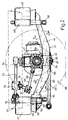
- Number 38 in Fig.s 1 and 2 indicates an assembly for the elastic suspension of a rear drive axle 40 of a bus.
- Assembly 38 comprises a pair of arms 41 (only one of which is shown) conveniently cast from spheroidal cast iron.
- said arms 41 are secured by a central portion 42 to a respective end of rear axle casing 43, and present an enclosed, hollow, quadrilateral section along rear portion 44 (Fig. 5), and a open-bottom, substantially C-shaped section along front portion 45 and the front portion of center portion 42 (Fig.4).
- Rear portions 44 of arms 41 extend upwards and outwards in relation to the mid longitudinal plane of the vehicle, and are secured at the ends, in known manner, to respective air-powered springs 47 and respective supports 48 on which pivot the bottom ends of respective dampers 49.
- Front portions 45 of arms 41 slope upwards, and terminate with respective substantially flat end flanges 50.
- Said flanges 50 provide for butt connecting arms 41 to a cross member 54, the end portions 55 of which project laterally outwards of arms 41, and are fitted with respective air-powered springs 47 and supports 48 for securing dampers 49.
- Cross member 54 presents a substantially quadrilateral section, and is formed by welding two superimposed shells 56, 57 (Fig.3).
- Bottom shell 56 presents a constant section over its entire length, whereas top shell 57 is lower at end portions 55 than over the center portion of cross member 54 extending between the arm 41 connecting portions.
- cross member 54 is fitted with two shaped supporting elements 58 having a section substantially in the form of an upside down U.
- elements 58 and in bottom shell 56 of cross member 54 close to supporting elements 58, provision is made for a number of through bushes 59 for receiving the bolts securing arms 41 to cross member 54.
- Assembly 38 comprises a pair of bottom longitudinal reaction bars 60 connected by a respective rear end to arms 41, via articulated ball joints 64 with elastic bushes (not shown), and by a respective front end to respective supporting means integral with a known underbody (not shown).
- a center portion 42 of arms 41 there are formed two transverse seats 65 for the respective ends of a center pin 66 of a corresponding articulated ball joint 64 secured inside said seats by means of screws 67.
- the rear ends of reaction bars 60 are therefore housed inside the cavities of arms 41, thus enabling vertical rebound of the same.
- Assembly 38 also comprises, in known manner, a substantially U-shaped stabilizing bar 68 forming two end portions 69 arranged longitudinally in relation to the vehicle and pivoting on a respective bracket 39, and a center portion 70 arranged crosswise in relation to the vehicle and to which are hinged the bottom ends of a pair of hangers 71, the top ends of which pivot on respective supports 72 integral with the vehicle underbody.
- Assembly 38 also comprises a pair of top reaction bars 73 arranged in the form of a triangle and having respective rear ends secured to a common V-shaped support 75 secured in articulated manner to the center of rear axle casing 43, and respective front ends secured in articulated manner to respective supports 76 integral with the underbody.
- connection of reaction bars 60 inside the cavity of arms 41 provides for increasing the center distance between the same as compared with existing known solutions, thus increasing the torque arm and so reducing torque intensity under given external stress, as well as distortion of the elastic bushes on articulated joints 64.
- this therefore provides for improving driving precision, or, alternatively, for a given driving precision, for employing more flexible articulated joints and so improving passenger comfort.
- reaction bars 60 in no way reduces the center distance of air-powered springs 47 or dampers 49, by virtue of the special design of rear portions 44 of arms 41 and the presence of cross member 54, thus in no way impairing the righting effect of springs 47 or performance of dampers 49.
- cross member 54 provides for obtaining the maximum possible center distance between air-powered springs 47 and dampers 49, without torquing front portions 45 of arms 41, which present an open section (and, therefore, lower torsional resistance) for housing and enabling rebound of torque bars 60.
- the loads transmitted by springs 47 and dampers 49 exert bending stress on cross member 54, which presents a section having a greater moment of inertia over the center portion where the bending moment is greatest.
- triangle bars 73 may be replaced by a top longitudinal torque bar and a cross bar. Changes may also be made to the section of arms 41 and the manner in which these are secured to springs 47, dampers 49, cross member 54, rear axle casing 43, and reaction bars 60. Moreover, assembly 38 may be applied, not only to a bus, but to any type of motor vehicle.
Landscapes
- Engineering & Computer Science (AREA)
- Mechanical Engineering (AREA)
- Vehicle Body Suspensions (AREA)
Claims (12)
Applications Claiming Priority (2)
| Application Number | Priority Date | Filing Date | Title |
|---|---|---|---|
| IT5314988U | 1988-05-13 | ||
| IT5314988U IT214322Z2 (it) | 1988-05-13 | 1988-05-13 | Gruppo per la sospensione elastica di un assale di un autoveicolo |
Publications (3)
| Publication Number | Publication Date |
|---|---|
| EP0341634A2 EP0341634A2 (de) | 1989-11-15 |
| EP0341634A3 EP0341634A3 (en) | 1989-12-13 |
| EP0341634B1 true EP0341634B1 (de) | 1992-07-08 |
Family
ID=11280357
Family Applications (1)
| Application Number | Title | Priority Date | Filing Date |
|---|---|---|---|
| EP19890108254 Expired EP0341634B1 (de) | 1988-05-13 | 1989-05-08 | Montagevorrichtung für die elastische Aufhängung einer Kraftfahrzeugachse |
Country Status (4)
| Country | Link |
|---|---|
| EP (1) | EP0341634B1 (de) |
| DE (1) | DE68902009T2 (de) |
| ES (1) | ES2033484T3 (de) |
| IT (1) | IT214322Z2 (de) |
Cited By (1)
| Publication number | Priority date | Publication date | Assignee | Title |
|---|---|---|---|---|
| WO2001034416A1 (de) | 1999-11-08 | 2001-05-17 | Steyr Daimler Puch Fahrzeugtechnik Ag & Co Kg | Hinterachsaufhängung für ein nutzfahrzeug und fahrzeug mit einer solchen |
Families Citing this family (8)
| Publication number | Priority date | Publication date | Assignee | Title |
|---|---|---|---|---|
| DE69313250T3 (de) † | 1992-11-27 | 2000-12-21 | Magyar Vagon- Es Gepgyar, Gyoer | Achse für Fahrzeuge |
| DE19756059C2 (de) * | 1997-12-17 | 2003-03-27 | Daimler Chrysler Ag | Führungsvorrichtung für eine Kraftfahrzeugstarrachse |
| FR2815292B1 (fr) * | 2000-10-13 | 2003-06-13 | Gen Trailers France | Ensemble de bras de suspension et support de frein |
| US6676143B2 (en) * | 2001-09-28 | 2004-01-13 | Meritor Heavy Vehicle Technology, Llc | Modular suspension arm assembly |
| WO2005080101A1 (en) * | 2004-02-25 | 2005-09-01 | Kongsberg Automotive As | Ball joint |
| WO2006067551A1 (en) * | 2004-12-21 | 2006-06-29 | Renault Trucks | Suspension for a vehicle |
| DE102014016678A1 (de) * | 2014-11-12 | 2016-05-12 | Man Truck & Bus Ag | Luftfederträger für eine luftgefederte Achse eines Nutzfahrzeugs |
| ES2844204T3 (es) * | 2015-07-23 | 2021-07-21 | Iveco Magirus | Suspensión de eje neumático para un eje posterior de un vehículo |
Family Cites Families (5)
| Publication number | Priority date | Publication date | Assignee | Title |
|---|---|---|---|---|
| US1995375A (en) * | 1931-12-10 | 1935-03-26 | Nathan A Carter | Vehicle wheel mounting |
| US2180860A (en) * | 1937-09-17 | 1939-11-21 | Firestone Tire & Rubber Co | Vehicle suspension |
| US2589043A (en) * | 1947-08-06 | 1952-03-11 | William M Brewen | Frame for vehicles |
| DE1225973B (de) * | 1956-05-11 | 1966-09-29 | Daimler Benz Ag | Gabelartig ausgebildeter Fuehrungslenker fuer Kraftfahrzeugachsen, insbesondere fuer Grosskraftfahrzeuge wie Omnibusse od. dgl. |
| US4343375A (en) * | 1979-10-22 | 1982-08-10 | Manning Donald L | Vehicle drive wheel suspension |
-
1988
- 1988-05-13 IT IT5314988U patent/IT214322Z2/it active
-
1989
- 1989-05-08 DE DE1989602009 patent/DE68902009T2/de not_active Expired - Fee Related
- 1989-05-08 ES ES89108254T patent/ES2033484T3/es not_active Expired - Lifetime
- 1989-05-08 EP EP19890108254 patent/EP0341634B1/de not_active Expired
Cited By (1)
| Publication number | Priority date | Publication date | Assignee | Title |
|---|---|---|---|---|
| WO2001034416A1 (de) | 1999-11-08 | 2001-05-17 | Steyr Daimler Puch Fahrzeugtechnik Ag & Co Kg | Hinterachsaufhängung für ein nutzfahrzeug und fahrzeug mit einer solchen |
Also Published As
| Publication number | Publication date |
|---|---|
| IT8853149V0 (it) | 1988-05-13 |
| DE68902009D1 (de) | 1992-08-13 |
| EP0341634A2 (de) | 1989-11-15 |
| ES2033484T3 (es) | 1993-03-16 |
| DE68902009T2 (de) | 1993-02-25 |
| IT214322Z2 (it) | 1990-05-03 |
| EP0341634A3 (en) | 1989-12-13 |
Similar Documents
| Publication | Publication Date | Title |
|---|---|---|
| US4432564A (en) | Rear suspension assembly for motor vehicles | |
| US4486030A (en) | Rear suspension apparatus for motor vehicle | |
| US4826203A (en) | Automobile sub-frame structure | |
| US6357772B1 (en) | Rear wheel suspension and subframe for the front or rear wheel suspension of a motor vehicle | |
| EP0298929B1 (de) | Hinterachsenaufhängung für Kraftfahrzeuge | |
| US5641175A (en) | Suspension system for automobile | |
| EP0240649A2 (de) | Radaufhängung mit Schwingarm und Befestigung der Achse durch den Druck einer Platte | |
| US4168086A (en) | Radius arm support for a driving axle | |
| PL179633B1 (pl) | Zawieszenie osi sztywnej w pojazdach PL | |
| CZ290731B6 (cs) | Závěs tuhé nápravy vozidla | |
| EP0341634B1 (de) | Montagevorrichtung für die elastische Aufhängung einer Kraftfahrzeugachse | |
| JPH11254935A (ja) | 車両用スタビライザ― | |
| US4714132A (en) | Suspension of vehicle | |
| US7967307B2 (en) | Heavy duty trailing arm suspension system | |
| US4790560A (en) | Independent rear suspension for use on motor vehicles | |
| US4256327A (en) | Torsion type tandem suspension | |
| US4632422A (en) | Anti-roll torsion bar (stabilizer) for the running gear of vehicles | |
| JP4058778B2 (ja) | 車両のサブフレーム構造 | |
| EP0563810B1 (de) | Radaufhängungsvorrichtung für einen lenkbaren Vorderradsatz eines Nutzfahrzeuges | |
| JPH0767881B2 (ja) | トレ−リングア−ム型リヤサスペンシヨン | |
| EP0233845B1 (de) | Motorfahrzeugaufhängung | |
| US4875705A (en) | Automobile rear suspension structure | |
| JP2881536B2 (ja) | サスペンション用サブフレーム | |
| EP0102772B1 (de) | Aufhängung für Fahrzeuge | |
| JP3350602B2 (ja) | 自動車のサブフレーム |
Legal Events
| Date | Code | Title | Description |
|---|---|---|---|
| PUAI | Public reference made under article 153(3) epc to a published international application that has entered the european phase |
Free format text: ORIGINAL CODE: 0009012 |
|
| PUAL | Search report despatched |
Free format text: ORIGINAL CODE: 0009013 |
|
| AK | Designated contracting states |
Kind code of ref document: A2 Designated state(s): DE ES FR GB IT NL SE |
|
| AK | Designated contracting states |
Kind code of ref document: A3 Designated state(s): DE ES FR GB IT NL SE |
|
| 17P | Request for examination filed |
Effective date: 19900529 |
|
| 17Q | First examination report despatched |
Effective date: 19910913 |
|
| GRAA | (expected) grant |
Free format text: ORIGINAL CODE: 0009210 |
|
| AK | Designated contracting states |
Kind code of ref document: B1 Designated state(s): DE ES FR GB IT NL SE |
|
| REF | Corresponds to: |
Ref document number: 68902009 Country of ref document: DE Date of ref document: 19920813 |
|
| ET | Fr: translation filed | ||
| ITF | It: translation for a ep patent filed | ||
| REG | Reference to a national code |
Ref country code: ES Ref legal event code: FG2A Ref document number: 2033484 Country of ref document: ES Kind code of ref document: T3 |
|
| PLBE | No opposition filed within time limit |
Free format text: ORIGINAL CODE: 0009261 |
|
| STAA | Information on the status of an ep patent application or granted ep patent |
Free format text: STATUS: NO OPPOSITION FILED WITHIN TIME LIMIT |
|
| 26N | No opposition filed | ||
| EAL | Se: european patent in force in sweden |
Ref document number: 89108254.7 |
|
| PGFP | Annual fee paid to national office [announced via postgrant information from national office to epo] |
Ref country code: FR Payment date: 19950424 Year of fee payment: 7 |
|
| PGFP | Annual fee paid to national office [announced via postgrant information from national office to epo] |
Ref country code: GB Payment date: 19950505 Year of fee payment: 7 |
|
| PGFP | Annual fee paid to national office [announced via postgrant information from national office to epo] |
Ref country code: ES Payment date: 19950512 Year of fee payment: 7 |
|
| PGFP | Annual fee paid to national office [announced via postgrant information from national office to epo] |
Ref country code: SE Payment date: 19950517 Year of fee payment: 7 |
|
| PGFP | Annual fee paid to national office [announced via postgrant information from national office to epo] |
Ref country code: NL Payment date: 19950531 Year of fee payment: 7 Ref country code: DE Payment date: 19950531 Year of fee payment: 7 |
|
| PG25 | Lapsed in a contracting state [announced via postgrant information from national office to epo] |
Ref country code: GB Effective date: 19960508 |
|
| PG25 | Lapsed in a contracting state [announced via postgrant information from national office to epo] |
Ref country code: SE Effective date: 19960509 Ref country code: ES Free format text: LAPSE BECAUSE OF NON-PAYMENT OF DUE FEES Effective date: 19960509 |
|
| PG25 | Lapsed in a contracting state [announced via postgrant information from national office to epo] |
Ref country code: NL Effective date: 19961201 |
|
| GBPC | Gb: european patent ceased through non-payment of renewal fee |
Effective date: 19960508 |
|
| PG25 | Lapsed in a contracting state [announced via postgrant information from national office to epo] |
Ref country code: FR Effective date: 19970131 |
|
| PG25 | Lapsed in a contracting state [announced via postgrant information from national office to epo] |
Ref country code: DE Effective date: 19970201 |
|
| EUG | Se: european patent has lapsed |
Ref document number: 89108254.7 |
|
| NLV4 | Nl: lapsed or anulled due to non-payment of the annual fee |
Effective date: 19961201 |
|
| REG | Reference to a national code |
Ref country code: FR Ref legal event code: ST |
|
| REG | Reference to a national code |
Ref country code: ES Ref legal event code: FD2A Effective date: 19990405 |
|
| PG25 | Lapsed in a contracting state [announced via postgrant information from national office to epo] |
Ref country code: IT Free format text: LAPSE BECAUSE OF NON-PAYMENT OF DUE FEES;WARNING: LAPSES OF ITALIAN PATENTS WITH EFFECTIVE DATE BEFORE 2007 MAY HAVE OCCURRED AT ANY TIME BEFORE 2007. THE CORRECT EFFECTIVE DATE MAY BE DIFFERENT FROM THE ONE RECORDED. Effective date: 20050508 |