EP0341563A2 - Inclined lift comprising several telescopic elements - Google Patents
Inclined lift comprising several telescopic elements Download PDFInfo
- Publication number
- EP0341563A2 EP0341563A2 EP89107987A EP89107987A EP0341563A2 EP 0341563 A2 EP0341563 A2 EP 0341563A2 EP 89107987 A EP89107987 A EP 89107987A EP 89107987 A EP89107987 A EP 89107987A EP 0341563 A2 EP0341563 A2 EP 0341563A2
- Authority
- EP
- European Patent Office
- Prior art keywords
- guide rails
- rail
- ifk
- narrow track
- telescopic
- Prior art date
- Legal status (The legal status is an assumption and is not a legal conclusion. Google has not performed a legal analysis and makes no representation as to the accuracy of the status listed.)
- Granted
Links
Images


Classifications
-
- E—FIXED CONSTRUCTIONS
- E06—DOORS, WINDOWS, SHUTTERS, OR ROLLER BLINDS IN GENERAL; LADDERS
- E06C—LADDERS
- E06C1/00—Ladders in general
- E06C1/02—Ladders in general with rigid longitudinal member or members
- E06C1/34—Ladders attached to structures, such as windows, cornices, poles, or the like
- E06C1/345—Ladders attached to structures, such as windows, cornices, poles, or the like specially adapted to be installed parallel to the roof surface
-
- B—PERFORMING OPERATIONS; TRANSPORTING
- B66—HOISTING; LIFTING; HAULING
- B66B—ELEVATORS; ESCALATORS OR MOVING WALKWAYS
- B66B9/00—Kinds or types of lifts in, or associated with, buildings or other structures
- B66B9/16—Mobile or transportable lifts specially adapted to be shifted from one part of a building or other structure to another part or to another building or structure
-
- E—FIXED CONSTRUCTIONS
- E06—DOORS, WINDOWS, SHUTTERS, OR ROLLER BLINDS IN GENERAL; LADDERS
- E06C—LADDERS
- E06C7/00—Component parts, supporting parts, or accessories
- E06C7/12—Lifts or other hoisting devices on ladders
-
- E—FIXED CONSTRUCTIONS
- E06—DOORS, WINDOWS, SHUTTERS, OR ROLLER BLINDS IN GENERAL; LADDERS
- E06C—LADDERS
- E06C7/00—Component parts, supporting parts, or accessories
- E06C7/48—Ladder heads; Supports for heads of ladders for resting against objects
- E06C7/488—Supports specially adapted to attach a ladder to a ridge of a roof
Definitions
- the invention relates to an inclined elevator formed from a plurality of telescopic sections, the individual telescopic sections having mirror-inverted mutually arranged guide rails connected by rungs, which are each guided on the guide rails of the previous telescopic section and on which a load-carrying means is guided by means of rollers.
- Inclined elevators of this type which, for example, have five or more guide rails and the last (upper) guide rail can possibly be bent.
- Such inclined elevators are used to transport loads from the ground level to the roof and vice versa. It is desirable to be able to operate not only the roof side on which the inclined lift - as a rule in the area of the eaves - is supported, but also the opposite side to operate the roof side.
- the object of the invention is to improve the guidance between the guide rollers of the load-carrying means and the guide rails of the inclined elevator in the region of the upper guide rail (s) and, in particular, to provide a way by which the roof ridge can be reliably guided by the load-carrying means to the guide or guides rails can be run over reliably.
- the load-carrying means is guided during the opening (this also applies vice versa for the departure) in the previously known manner on the positively guided guide rails of the inclined elevator by means of corresponding roller sets;
- the load-carrying device leads (still) over a short section on the known outer roller guide and then changes to the narrow track lying between the previously usual guide rails, for which purpose a corresponding inner roller guide is provided on the load-carrying device.
- the load suspension device leaves the known guide on the outer guide rails when further opening (or before moving down to the other side of the roof) and is carried on to the guide rails of the narrow track only via an inner roller set.
- the average center distance of the roller set of the rollers guided on the narrow track can be kept smaller than the average center distance of the outer rollers, so that the articulated joint in the ridge area can be passed over better. It is understood that the roller guide of the roller set for the narrow gauge can be matched very precisely to the narrow gauge, i.e. the play between the rollers and the profile of the narrow gauge can be kept relatively small, which leads to a reliable overrun of the roof.
- the use of the narrow gauge is suitable better guidance of the load suspension device in the area of the upper guide rail (s), ie not only for passing over the roof.
- the guide rails of the narrow gauge can be telescoped with respect to the last (upper) telescopic section, so to speak they form an integrated guide rail and, if used appropriately, an integrated ridge buckle (IFK).
- the narrow track can be constructed from two guide rails connected in a ladder-like manner by rungs; since these guide rails forming the last telescopic section are not guided in the guide rails of the previously known type, they are positively guided in slide shoes arranged on the rungs of the last (upper) telescopic section.
- the guide rails of the narrow gauge have U-profiles with U-legs pointing away from each other, so that the inward-facing roller set of the load-carrying means can be guided on the upper of these U-legs.
- the guide rails of the narrow track are provided with an articulated joint which, according to claim 6, is designed as a stiffened multiple joint in such a way that the individual joint sections form the same articulation angle.
- the narrow track can consist of several telescopic sections, for example in such a way that the telescopic section forming the narrow track can be telescoped by means of a winch operated from the ground; in turn but takes an additional telescopic shot, which can be pulled out by hand, for example around the opposite roof side to the bottom end.
- the last (upper) guide rail, on which the narrow track is guided is designed as a so-called "rail zero"; this means that the rail has a profile with a relatively low web height;
- the rungs connecting the guide rails of the rail zero are cranked in order to leave the rope for telescoping the guide rails (telescopic rope) sufficient play between the rungs of the adjacent guide rails.
- a particular advantage of the invention is seen in the fact that the web height of the guide rails of the narrow track can be greater than the web height of the guide rails on which the narrow track is slidably guided.
- This advantage results from the fact that the rail profile of the narrow track lies between the rail profiles of the other telescopic sections, so that there is no height limitation for this.
- interlocks are provided on the one hand between the narrow track and the last (upper) telescopic section and on the other hand between the last (upper) and the subsequent lower telescopic section (claims 10 and 11).
- a special embodiment of the invention results when the narrow track is to be used as a so-called integrated ridge buckle (IFK);
- IFN integrated ridge buckle
- a so-called zero rail is used as the last (upper) telescopic section; this rail serves as by means of a ground-operated winch telescopic compensation rail, with which the articulation of the narrow track can be moved exactly over the ridge (claim 15).
- the narrow gauge is called IFK (Inte grated ridge elbow).
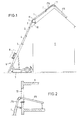
- an inclined elevator designated 6 can be seen, which is supported by a chassis 7 on the floor.
- the inclined elevator has guide rails 0 - 1 and an IFK guide rail, all of which can be telescoped using a winch that can be operated from the ground.
- the guide rail 2 is supported on a building 9 in the area of the eaves 10.
- 11 and 17 designate articulated joints, the articulated joint 11 being assigned to the guide rail 1 and the articulated joint 17 being assigned to the IFK rail.
- a so-called zero rail is guided in the rail 1, in which the rail IFK is in turn slidably guided.
- the zero rail as will be explained in connection with the cable routing plan, is useful as a so-called compensating rail for adapting to the kinking over the roof.
- IFK material is brought through a window opening 12 by means of the rail; here the IFK rail runs directly in rail 1.
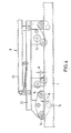
- the base frame 21 consists essentially of a base frame 21, on which an upper frame 22 is slidably guided.
- the base frame 21 has outer rollers 14 combined into roller sets and inner rollers 14 'combined into further roller sets.
- the outer rollers 14 run on the rails 5-0 (in the exemplary embodiment shown on the rail 1); the inner rollers 14 'on the guide rail IFK indicated in the picture plane in Fig. 3 above. It is can be seen that the average center distance a of the roller sets of the rollers 14 'is significantly smaller than the average center distance A of the roller sets of the rollers 14. This improves the overrun of the articulated joint 17 of the rail IFK. 23 with a lock is designated by means of which the upper frame can be locked to the base frame.
- Fig. 4 illustrates that the game k between the top roller and the bottom roller of the inward roller set of rollers 14 'can be kept significantly lower than the game K between the top roller and bottom roller of the roller set of rollers 14 to improve the leadership in the ridge area.
- the rollers 14 are still guided on the rail zero; the rollers 14 'already track with little play in the IFK rail.
- the IFK rail can in turn be telescoped; it leads in sliding shoes 16, which are welded to the cranked rungs 13, which connect the profiles of the rail 0.
- Fig. 6 further shows that the web height H of the rail IFK can be chosen larger than the web height h of the rail 0, because the rail IFK does not have to be positively guided in the rail 0, as is the case with the other guide rails.
- the narrower construction of the IFK rail (Narrow gauge), sufficient stiffness of the IFK rail can be achieved.
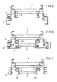
- FIG. 8 shows a top view of the transition area from the rail 1 to the rail 0 and the rail IFK.
- a lock designated 19 which in the exemplary embodiment can be inserted by hand.
- the lock 19 designed as a camshaft makes it possible to fix the rail 0 to the rungs 20 of the rail 1 so that it cannot move.
- Another lock 18 is provided between the rail 0 and the rail IFK, which can also be operated by hand in the embodiment shown.
- the lock 18 defines the rail IFK on the rungs 13 'of the rail 0.
- the rail IFK is prevented from sliding on the slide rail 16.
- FIG. 9 shows the locking situation of the rail 0 with respect to the rail 1, which is also illustrated by FIG. 10 (section IX-IX according to FIG. 9).
- the interlocks according to FIGS. 8-10 are useful when the rail is passed over by the IFK rail.
- the individual guide rails are shown side by side in the cable routing plan.
- the telescopic cable 24 runs from the winch 25 to the upper end of the rail No. 5, further to the lower end of the rail No. 4, with multiple deflection to the upper end of the rail No. 4, to the lower end of the rail No. 3, to the upper End of rail no. 2 etc. and ends at the lower end of rail IFK. All rails can thus be extended with the telescopic cable 24.
- a so-called finite rope 26 runs from the central region of the rail No. 5 to the upper end of the rail No. 4 and is deflected at the lower end of the rail No. 3 via rollers.
- Another so-called finite rope 27 runs from the lower end of rail No. 4 over the upper end of rail No. 3 and is deflected at the lower end of rail No. 2 via rollers.
- the rail No. 1 extends;
- the rail No. 1 is lowered together with the rail No. 0 and the rail IFK against the roof surface in a known manner after latching into a lock.
- the lock 18 between the rail IFK and the rail 0 released so that the rail IFK can extend relative to the rail 0.
- the lock 19 between the rail No. 1 and the rail 0 remains.
- the IFK rail is locked with respect to the 0 rail by means of the lock 18.
- the IFK rail is already lowered on the opposite side of the roof.
- the lock 19 between the rail 1 and the rail 0 is released and the rail 0 is moved as a so-called compensating rail into the required position (depending on the length of the roof surface).
- the locking device 10 is inserted between the rail No. 1 and the rail 0 and the rail IFK is lowered into the final position.
- the rail 0 is extended to the desired compensation position, the IFK rail is already lowered on the rear roof surface.
- the rail 0 is then finally locked with respect to the rail 1 by means of the lock 19.
- the rail 0 When retracting, the rail 0 is preferably first retracted after the lock 19 has been released. After retraction of the rail 0 in the rail 1, the lock 19 is reinserted; the lock 18 between rail 0 and rail IFK is released by hand and the rail IFK is moved into rail 0. Then the locking between rail 0 and the rail IFK takes place by means of the locking device 18.
- the remaining telescopic sections can be retracted in a known manner.
Abstract
Description
Die Erfindung betrifft einen aus mehreren Teleskopschüssen gebildeten Schrägaufzug, dessen einzelne Teleskopschüsse spiegelbildlich zueinander angeordnete, durch Sprossen leiterartig verbundene Führungsschienen aufweisen, die jeweils an den Führungsschienen des vorhergehenden Teleskopschusses geführt sind, und an denen ein Lastaufnahmemittel mittels Rollen geführt ist.The invention relates to an inclined elevator formed from a plurality of telescopic sections, the individual telescopic sections having mirror-inverted mutually arranged guide rails connected by rungs, which are each guided on the guide rails of the previous telescopic section and on which a load-carrying means is guided by means of rollers.
Es sind derartige Schrägaufzüge bekannt, die beispielsweise fünf oder mehr Führungsschienen aufweisen und wobei die letzte (obere) Führungsschiene ggf. abknickbar ist. Derartige Schrägaufzüge dienen zum Transport von Lasten vom ebenerdigen Bereich zum Dach bzw. umgekehrt. Dabei ist es wünschenswert, nicht nur die Dachseite bedienen zu können, an der der Schrägaufzug- im Regelfall im Bereich der Traufe - abgestützt ist, sondern zusätzlich auch die gegenüberlie gende Dachseite bedienen zu können.Inclined elevators of this type are known which, for example, have five or more guide rails and the last (upper) guide rail can possibly be bent. Such inclined elevators are used to transport loads from the ground level to the roof and vice versa. It is desirable to be able to operate not only the roof side on which the inclined lift - as a rule in the area of the eaves - is supported, but also the opposite side to operate the roof side.
Man hat hierzu bereits vorgeschlagen, am oberen freien Ende des letzten (oberen) Teleskopschusses ein lösbares Knickstück anzuschrauben, in dem eine Führungsschiene geführt ist, die der gegenüberliegenden Dachseite anliegt, so daß das an den Führungsschienen in bekannter Weise verfahrbare Lastaufnahmemittel über das Knickstück auf die andere Dachseite verfahren werden kann.For this purpose, it has already been proposed to screw a detachable bend piece onto the upper free end of the last (upper) telescopic section, in which a guide rail is guided which rests on the opposite side of the roof, so that the load-carrying means, which can be moved on the guide rails in a known manner, passes over the bend piece onto the other roof side can be moved.
Hierzu sind regelmäßig zeitaufwendige und gefahrvolle Montagearbeiten im Bereich des Dachfirstes erforderlich.This regularly requires time-consuming and dangerous assembly work in the area of the roof ridge.
Generell wird bei den bekannten Schrägaufzügen ein Nachteil darin empfunden, daß bei einer größeren Anzahl von teleskopierbaren Führungsschienen der Rollenabstand zwischen den Unterrollen und Oberrollen des Lastaufnahmemittels relativ groß gewählt werden muß, damit das Lastaufnahmemittel auch noch im zusammengeschobenen Zustand der Führungsschienen diese überfahren kann. Daraus resultiert, daß beim Ueberfahren der letzten (oberen) Führungsschiene im ausgefahrenen Zustand der Führungsschienen ein relativ großes Spiel zwischen Oberrolle und Unterrolle gegeben ist, was zu einer wenig definierten Führung des Lastaufnahmemittels im oberen Bereich des Schrägaufzuges führt.In general, a disadvantage in the known inclined elevators is felt in that, with a larger number of telescopic guide rails, the roller spacing between the lower rollers and upper rollers of the load-carrying means must be chosen to be relatively large, so that the load-carrying means can still run over them when the guide rails are pushed together. The result of this is that when the last (upper) guide rail is passed over when the guide rails are extended, there is a relatively large amount of play between the upper roller and lower roller, which leads to less defined guidance of the load suspension device in the upper region of the inclined elevator.
Aufgabe der Erfindung ist es, die Führung zwischen den Führungsrollen des Lastaufnahmemittels und den Führungsschienen des Schrägaufzuges im Bereich der oberen Führungsschiene(n) zu verbessern und insbesondere eine Möglichkeit zu schaffen, mit der der Dachfirst zuverlässig unter exakter Führung des Lastaufnahmemittels an der oder den Führungs schienen zuverlässig überfahren werden kann.The object of the invention is to improve the guidance between the guide rollers of the load-carrying means and the guide rails of the inclined elevator in the region of the upper guide rail (s) and, in particular, to provide a way by which the roof ridge can be reliably guided by the load-carrying means to the guide or guides rails can be run over reliably.
Die Erfindung löst die gestellte Aufgabe durch die Lehre nach Anspruch 1. Hiernach wird das Lastaufnahmemittel während des Auffahrens (dies gilt jeweils umgekehrt auch für das Abfahren) in der bisher bekannten Weise an den einander zwangsgeführten Führungsschienen des Schrägaufzuges mittels entsprechender Rollensätze geführt; im Firstbereich führt sich jedoch in neuartiger Weise das Lastaufnahmemittel über einen kurzen Abschnitt (noch) an der bekannten äußeren Rollenführung und wechselt dann auf die zwischen den bisher üblichen Führungsschienen liegende Schmalspur, wozu eine entsprechende innere Rollenführung am Lastaufnahmemittel vorgesehen ist. Das Lastaufnahmemittel verläßt beim weiteren Auffahren (bzw. vor dem Abfahren auf die andere Dachseite) die bekannte Führung an den äußeren Führungsschienen und wird ausschließlich über einen inneren Rollensatz an den Führungsschienen der Schmalspur weiter geführt. Dies hat den besonderen Vorteil, daß der mittlere Achsabstand des Rollensatzes der an der Schmalspur geführten Rollen geringer gehalten werden kann als der mittlere Achsabstand der äußeren Rollen, so daß das Knickgelenk im Firstbereich besser überfahren werden kann. Es versteht sich, daß die Rollenführung des Rollensatzes für die Schmalspur sehr exakt auf die Schmalspur abgestimmt werden kann, d.h., das Spiel zwischen den Rollen und dem Profil der Schmalspur kann relativ gering gehalten werden, was zu einem zuverlässigen Ueberfahren der Firste führt.The invention solves the stated problem by the teaching according to
Weitere Merkmale der Erfindung sind durch die Unteransprüche gekennzeichnet.Further features of the invention are characterized by the subclaims.
Grundsätzlich eignet sich die Verwendung der Schmalspur zur besseren Führung des Lastaufnahmemittels im Bereich der oberen Führungsschiene(n), d.h., nicht nur zum Ueberfahren der Firste.Basically, the use of the narrow gauge is suitable better guidance of the load suspension device in the area of the upper guide rail (s), ie not only for passing over the roof.
Nach der Erfindung sind die Führungsschienen der Schmalspur gegenüber dem letzten (oberen) Teleskopschuß teleskopierbar, sie bilden gewissermaßen eine integrierte Führungsschiene, bei entsprechender Verwendung ein integriertes First-Knickstück (IFK). Grundsätzlich kann die Schmalspur wie die bisher bekannten Teleskopschüsse aus zwei, durch Sprossen leiterartig verbundene Führungsschienen aufgebaut sein; da diese den letzten Teleskopschuß bildenden Führungsschienen nicht in den Führungsschienen der bisher bekannten Bauart geführt sind, sind sie gemäß Anspruch 4 in an den Sprossen des letzten (oberen) Teleskopschusses angeordneten Gleitschuhen zwangsgeführt. Die Führungsschienen der Schmalspur weisen U-Profile auf mit voneinander wegweisenden U-Schenkeln, so daß der nach innen weisende Rollensatz des Lastaufnahmemittels sich an dem oberen dieser U-Schenkel führen kann.According to the invention, the guide rails of the narrow gauge can be telescoped with respect to the last (upper) telescopic section, so to speak they form an integrated guide rail and, if used appropriately, an integrated ridge buckle (IFK). In principle, like the previously known telescopic sections, the narrow track can be constructed from two guide rails connected in a ladder-like manner by rungs; since these guide rails forming the last telescopic section are not guided in the guide rails of the previously known type, they are positively guided in slide shoes arranged on the rungs of the last (upper) telescopic section. The guide rails of the narrow gauge have U-profiles with U-legs pointing away from each other, so that the inward-facing roller set of the load-carrying means can be guided on the upper of these U-legs.
Zum Ueberfahren der Firste sind die Führungsschienen der Schmalspur mit einem Knickgelenk versehen, welches gemäß Anspruch 6 als in sich ausgesteiftes Mehrfachgelenk ausgebildet ist, derart, daß die einzelnen Gelenkabschnitte gleiche Knickwinkel bilden.To drive over the roof, the guide rails of the narrow track are provided with an articulated joint which, according to claim 6, is designed as a stiffened multiple joint in such a way that the individual joint sections form the same articulation angle.
Die Schmalspur kann gemäß Anspruch 7 aus mehreren Teleskopschüssen bestehen, beispielsweise derart, daß der die Schmalspur bildende Teleskopschuß mittels einer vom Boden bedienbaren Winde teleskopierbar ist; seinerseits aber einen zusätzlichen Teleskopschuß aufnimmt, welcher von Hand ausziehbar ist, um beispielsweise die gegenüberliegende Dach seite bis zum unteren Ende bedienen zu können.The narrow track can consist of several telescopic sections, for example in such a way that the telescopic section forming the narrow track can be telescoped by means of a winch operated from the ground; in turn but takes an additional telescopic shot, which can be pulled out by hand, for example around the opposite roof side to the bottom end.
In besonderer Ausgestaltung der Erfindung ist die letzte (obere) Führungsschiene, an der die Schmalspur gleitend geführt ist, als sogenannte "Schiene Null" ausgebildet; dies bedeutet, daß die Schiene ein Profil mit relativ geringer Steghöhe hat; zu diesem Zweck sind die die Führungsschienen der Schiene Null verbindenden Sprossen abgekröpft ausgebildet, um dem Seil zum Teleskopieren der Führungsschienen (Teleskopseil) ausreichendes Spiel zwischen den Sprossen der benachbarten Führungsschienen zu belassen.In a special embodiment of the invention, the last (upper) guide rail, on which the narrow track is guided, is designed as a so-called "rail zero"; this means that the rail has a profile with a relatively low web height; For this purpose, the rungs connecting the guide rails of the rail zero are cranked in order to leave the rope for telescoping the guide rails (telescopic rope) sufficient play between the rungs of the adjacent guide rails.
Ein besonderer Vorteil der Erfindung wird darin gesehen, daß die Steghöhe der Führungsschienen der Schmalspur größer sein kann als die Steghöhe der Führungsschienen, an dem die Schmalspur gleitend geführt ist. Dieser Vorteil ergibt sich daraus, daß das Schienenprofil der Schmalspur zwischen den Schienenprofilen der übrigen Teleskopschüsse liegt, so daß hierfür eine Höhenbegrenzung nicht gegeben ist.A particular advantage of the invention is seen in the fact that the web height of the guide rails of the narrow track can be greater than the web height of the guide rails on which the narrow track is slidably guided. This advantage results from the fact that the rail profile of the narrow track lies between the rail profiles of the other telescopic sections, so that there is no height limitation for this.
Um eine zuverlässige Ueberleitung der Schmalspur auf die andere Dachseite zu gewährleisten, sind einerseits zwischen der Schmalspur und dem letzten (oberen) Teleskopschuß und andererseits zwischen dem letzten (oberen) und dem nachfolgenden unteren Teleskopschuß Verriegelungen vorgesehen (Ansprüche 10 und 11).In order to ensure reliable transfer of the narrow track to the other roof side, interlocks are provided on the one hand between the narrow track and the last (upper) telescopic section and on the other hand between the last (upper) and the subsequent lower telescopic section (
Eine besondere Ausgestaltungsform der Erfindung ergibt sich, wenn die Schmalspur als sogenanntes integriertes First-Knickstück (IFK) Verwendung finden soll; wie vorerwähnt, wird hierzu als letzter (oberer) Teleskopschuß eine sogenannte Schiene Null benutzt; diese Schiene dient als mittels einer vom Boden bedienbaren Winde teleskopierbare Ausgleichsschiene, mit der das Knickgelenk der Schmalspur exakt über den First gefahren werden kann (Anspruch 15).A special embodiment of the invention results when the narrow track is to be used as a so-called integrated ridge buckle (IFK); As mentioned above, a so-called zero rail is used as the last (upper) telescopic section; this rail serves as by means of a ground-operated winch telescopic compensation rail, with which the articulation of the narrow track can be moved exactly over the ridge (claim 15).
Die Erfindung wird nachfolgend anhand eines Ausführungsbeispieles näher erläutert.The invention is explained in more detail below using an exemplary embodiment.
Es zeigen:
- Fig. 1 einen Schrägaufzug mit über den First verlaufenden Führungsschüssen
- Fig. 2 die Transportmöglichkeit durch eine Fensteröffnung
- Fig. 3 eine Draufsicht auf das Lastaufnahmemittel
- Fig. 4 eine Seitenansicht des Lastaufnahmemittels
- Fig. 5 einen Schnitt nach der Linie V-V gemäß Fig. 3
- Fig. 6 die Situation gemäß Fig. 5 beim Uebergang des Lastaufnahmemittels auf die Schmalspur
- Fig. 7 die Situation gemäß Fig. 6 bei ausschließlicher Führung des Lastaufnahmemittels an der Schmalspur
- Fig. 8 eine Draufsicht auf den Uebergangsbereich zwischen der Normalführung und der Schmalspur
- Fig. 9 einen Schnitt nach der Linie X-X gemäß Fig. 10
- Fig. 10 einen Schnitt nach der Linie IX-IX gemäß Fig. 9
- Fig. 11 einen Seilplan unter Verwendung der Schmalspur
- Fig. 1 is an inclined elevator with guide shots extending over the ridge
- Fig. 2 shows the possibility of transportation through a window opening
- Fig. 3 is a plan view of the load handling device
- Fig. 4 is a side view of the load handling device
- 5 shows a section along the line VV according to FIG. 3rd
- FIG. 6 shows the situation according to FIG. 5 at the transition of the load handler to the narrow track
- FIG. 7 shows the situation according to FIG. 6 with exclusive guidance of the load suspension device on the narrow track
- Fig. 8 is a plan view of the transition area between the normal guide and the narrow track
- 9 is a section along the line XX of FIG .. 10
- 10 shows a section along the line IX-IX according to FIG. 9
- Fig. 11 is a rope plan using the narrow gauge
Im Nachfolgenden wird die Schmalspur als Schiene IFK (Inte griertes First-Knickstück) bezeichnet.In the following, the narrow gauge is called IFK (Inte grated ridge elbow).
Aus der Fig. 1 ist ein mit 6 bezeichneter Schrägaufzug ersichtlich, welcher mittels eines Fahrgestells 7 auf dem Boden abgestützt ist. Der Schrägaufzug weist Führungsschienen 0 - 1 sowie eine Führungsschiene IFK auf, die sämtlich mittels einer vom Boden bedienbaren Winde teleskopierbar sind. In dem dargestellten Ausführungsbeispiel ist die Führungsschiene 2 im Bereich der Traufe 10 an einem Gebäude 9 abgestützt. Mit 11 und 17 sind Knickgelenke bezeichnet, wobei das Knickgelenk 11 der Führungsschiene 1 und das Knickgelenk 17 der Schiene IFK zugeordnet ist. In dem Ausführungsbeispiel nach Fig. 1 ist in der Schiene 1 eine sogenannte Schiene Null geführt, in der ihrerseits die Schiene IFK gleitend geführt ist. Die Schiene Null ist, wie im Zusammenhang mit dem Seilführungsplan noch erläutert werden wird, als sogenannte Ausgleichsschiene zur Anpassung an die Abknickung über die Firste zweckdienlich.From Fig. 1, an inclined elevator designated 6 can be seen, which is supported by a
Gemäß Fig. 2 wird mittels der Schiene IFK Material durch eine Fensteröffnung 12 verbracht; hier führt sich die Schiene IFK unmittelbar in der Schiene 1.2, IFK material is brought through a window opening 12 by means of the rail; here the IFK rail runs directly in
Das in der Fig. 3 dargestellte Lastaufnahmemittel besteht im wesentlichen aus einem Grundrahmen 21, an dem ein Oberrahmen 22 verschieblich geführt ist. Der Grundrahmen 21 weist zu Rollensätzen zusammengefaßte äußere Rollen 14 und zu weiteren Rollensätzen zusammenfaßte innere Rollen 14′ auf. Die äußeren Rollen 14 führen sich an den Schienen 5 - 0 (im aufgezeigten Ausführungsbeispiel an der Schiene 1); die inneren Rollen 14′ an der in der Bildebene in Fig. 3 oben andeutungsweise dargestellten Führungsschiene IFK. Es ist ersichtlich, daß der mittlere Achsabstand a der Rollensätze der Rollen 14′ deutlich kleiner ist als der mittlere Achsabstand A der Rollensätze der Rollen 14. Dies verbessert das Ueberfahren des Knickgelenkes 17 der Schiene IFK. Mit 23 ist eine Verriegelung bezeichnet, mittels der der Oberrahmen mit dem Grundrahmen verriegelbar ist.3 consists essentially of a
Insbesondere Fig. 4 verdeutlicht, daß das Spiel k zwischen Oberrolle und Unterrolle des nach innen gerichteten Rollensatzes der Rollen 14′ deutlich geringer gehalten werden kann als das Spiel K zwischen Oberrolle und Unterrolle des Rollensatzes der Rollen 14, um die Führung im Firstbereich zu verbessern.In particular, Fig. 4 illustrates that the game k between the top roller and the bottom roller of the inward roller set of
Gemäß Fig. 5 (Schnitt V-V nach Fig. 3) ist das Lastaufnahmemittel 8 noch an den Führungsschienen 1 des vorletzten Teleskopschusses mit den nach außen gerichteten Rollen 14 geführt. Die Rollen 14′ haben noch keine Führungsfunktion übernommen.5 (section V-V according to FIG. 3), the load-carrying
In der Endphase, in der das Lastaufnahmemittel 8 gemäß Fig. 6 die Schiene Null überfährt, sind die Rollen 14 noch an der Schiene Null geführt; die Rollen 14′ gleisen bereits mit geringem Spiel in die Schiene IFK ein. Die Schiene IFK kann ihrerseits teleskopiert werden; sie führt sich dabei in Gleitschuhen 16, welche mit den abgekröpften Sprossen 13, die die Profile der Schiene 0 verbinden, verschweißt sind. Fig. 6 zeigt weiter, daß die Steghöhe H der Schiene IFK größer gewählt werden kann, als die Steghöhe h der Schiene 0, weil die Schiene IFK nicht in der Schiene 0 zwangsgeführt werden muß, wie dies bei den übrigen Führungsschienen der Fall ist. Trotz der schmaleren Bauweise der Schiene IFK (Schmalspur) kann somit eine ausreichende Steifigkeit der Schiene IFK erreicht werden.In the final phase, in which the load-carrying
Wie Fig. 7 erkennen läßt, führen sich die nach innen gerichteten Rollen 14′ nach Verlassen der Schiene 0 ausschließlich mit geringem Spiel an dem Oberflansch der Schiene IFK. Diese Situation ist im oberen Bereich der ersten Dachseite und ausschließlich im gesamten Bereich der gegenüberliegenden Dachseite gegeben.As can be seen in FIG. 7, the inwardly directed
Fig. 8 zeigt eine Draufsicht auf den Uebergangsbereich von der Schiene 1 auf die Schiene 0 und die Schiene IFK. Zwischen der Schiene 1 und der Schiene 0 ist eine mit 19 bezeichnete Verriegelung vorgesehen, welche in dem Ausführungsbeispiel von Hand eingelegt werden kann. Die als Nockenwelle ausgebildete Verriegelung 19 ermöglicht es, die Schiene 0 an den Sprossen 20 der Schiene 1 verschiebungssicher festzulegen. Eine weitere Verriegelung 18 ist zwischen der Schiene 0 und der Schiene IFK vorgesehen, die ebenfalls in dem gezeigten Ausführungsbeispiel von Hand betätigt werden kann. Die Verriegelung 18 legt die Schiene IFK an den Sprossen 13′ der Schiene 0 fest. Damit ist die Schiene IFK gegen Gleitbewegung an der Gleitschiene 16 gehindert.FIG. 8 shows a top view of the transition area from the
Fig. 9 (Schnitt X-X nach Fig. 10) zeigt die Verriegelungssituation der Schiene 0 gegenüber der Schiene 1, was ebenfalls durch Fig. 10 (Schnitt IX-IX nach Fig. 9) verdeutlicht wird. Die Verriegelungen gemäß Fig. 8 - 10 sind, wie im folgenden anhand des Seilführungsplanes erläutert werden wird, beim Ueberfahren der Firste durch die Schiene IFK zweckdienlich.FIG. 9 (section XX according to FIG. 10) shows the locking situation of the
Im Seilführungsplan sind die einzelnen Führungsschienen nebeneinander dargestellt. Das Teleskopseil 24 verläuft von der Winde 25 zum oberen Ende der Schiene Nr. 5, weiter zum unteren Ende der Schiene Nr. 4, unter mehrfacher Umlenkung zum oberen Ende der Schiene Nr. 4, zum unteren Ende der Schiene Nr. 3, zum oberen Ende der Schiene Nr. 2 usw. und endet am unteren Ende der Schiene IFK. Mit dem Teleskopseil 24 können somit sämtliche Schienen ausgefahren werden.The individual guide rails are shown side by side in the cable routing plan. The
Vom mittleren Bereich der Schiene Nr. 5 läuft ein sogenanntes endliches Seil 26 zum oberen Ende der Schiene Nr. 4 und ist am unteren Ende der Schiene Nr. 3 über Rollen umgelenkt. Ein weiteres sogenanntes endliches Seil 27 verläuft vom unteren Ende der Schiene Nr. 4 über das obere Ende der Schiene Nr. 3 und ist am unteren Ende der Schiene Nr. 2 über Rollen umgelenkt.A so-called
Beim Betätigen der Winde 25 werden somit zwangsläufig die Schienen 4, 3 und 2 gemeinsam ausgefahren. Die Schienen 1, 0 und IFK verbleiben in Ruhe. Beim Erreichen der Traufe wird in bekannter Weise eine zwischen der Schiene 5 und der Schiene 4 vorgesehene, nicht dargestellte, sogenannte "Hauptverriegelung" eingelegt, so daß die Bewegung der endlichen Seile 26 und 27 blockiert ist, d.h. die Schienen 5, 4, 3 und 2 sind miteinander verriegelt.When the
Beim weiteren Betätigen der Winde 25 fährt die Schiene Nr. 1 aus; hierbei wird in bekannter Weise nach Einrasten in eine Verriegelung die Schiene Nr. 1 gemeinsam mit der Schiene Nr. 0 und der Schiene IFK gegen die Dachfläche abgesenkt. Im folgenden wird die Verriegelung 18 zwischen der Schiene IFK und der Schiene 0 gelöst, so daß die Schiene IFK gegenüber der Schiene 0 ausfahren kann. Die Verriegelung 19 zwischen der Schiene Nr. 1 und der Schiene 0 bleibt bestehen. Nach dem Ausfahren der Schiene IFK bis zum Endanschlag wird die Schiene IFK gegenüber der Schiene 0 mittels der Verriegelung 18 verriegelt. Dabei findet bereits eine Absenkung der Schiene IFK auf der gegenüberliegenden Dachseite statt.When the
Anschließend wird die Verriegelung 19 zwischen der Schiene 1 und der Schiene 0 gelöst und die Schiene 0 als sogenante Ausgleichsschiene in die erforderliche Position gefahren (je nach Länge der Dachfläche). Im folgenden wird die Verriegelung 10 zwischen der Schiene Nr. 1 und der Schiene 0 eingelegt und die Schiene IFK in die endgültige Position abgesenkt. Beim Ausfahren der Schiene 0 in die gewünschte Ausgleichsposition erfolgt gleichzeitig bereits das Absenken der Schiene IFK auf der rückwärtigen Dachfläche. Anschließend wird die Schiene 0 gegenüber der Schiene 1 mittels der Verriegelung 19 endgültig verriegelt.Then the
Beim Einfahren wird vorzugsweise zunächst die Schiene 0 nach dem Lösen der Verriegelung 19 eingefahren. Nach dem Einfahren der Schiene 0 in die Schiene 1 wird die Verriegelung 19 wieder eingelegt; die Verriegelung 18 zwischen Schiene 0 und Schiene IFK wird von Hand gelöst und die Schiene IFK wird in die Schiene 0 eingefahren. Anschließend erfolgt die Verriegelung zwischen Schiene 0 und der Schiene IFK durch die Verriegelung 18.When retracting, the
Im folgenden können die übrigen Teleskopschüsse in bekannter Weise eingefahren werden.In the following, the remaining telescopic sections can be retracted in a known manner.
- IFK = Schmalspur (Integriertes First-Knickstück)IFK = narrow gauge (integrated ridge buckle)
- 0 = )0 =)
- 1 = )1 =)
- 2 = ) Führungsschienen der Teleskopschüsse2 =) Guide rails of the telescopic sections
- 3 = )3 =)
- 4 = )4 =)
- 5 = )5 =)
- 6 = Schrägaufzug6 = inclined elevator
- 7 = Fahrgestell7 = chassis
- 8 = Lastaufnahmemittel8 = load handler
- 9 = Gebäude9 = building
- 10 = Traufe10 = eaves
- 11 = Knickgelenk11 = articulated joint
- 12 = Fensteröffnung12 = window opening
- 13 = Sprossen zwischen Führungsschienen IFK13 = Rungs between guide rails IFK
-
13′ = Sprossen zwischen Schienen 013 ′ = rungs between
rails 0 - 14 = Rollen nach außen weisend14 = rolls pointing outwards
- 14′ = Rollen nach innen weisend14 ′ = rollers pointing inwards
- 15 = U-Schenkel der Führungsschienen IFK15 = U-leg of the IFK guide rails
- 16 = Gleitschiene16 = slide rail
- 17 = Knickgelenk in Schiene IFK17 = articulated joint in IFK splint
-
18 = Verriegelung zwischen Führungsschiene IFK und Führungsschiene 1 oder 018 = interlock between guide rail IFK and
guide rail -
19 = Verriegelung zwischen Führungsschiene 0 und Führungsschiene 119 = locking between
guide rail 0 andguide rail 1 -
20 = Sprossen zwischen den Führungsschienen 120 = rungs between the
guide rails 1 - 21 = Grundrahmen21 = base frame
- 22 = Oberrahmen22 = top frame
- 23 = Verriegelung23 = locking
- 24 = Teleskopseil24 = telescopic rope
- 25 = Winde25 = winch
- 26 = endliches Seil26 = finite rope
- 27 = endliches Seil27 = finite rope
- H = Steghöhe der Scheinen IFKH = bridge height of IFK notes
-
h = Steghöhe der Schiene 0h = web height of the
rail 0 - a = Achsabstand des inneren Rollensatzesa = center distance of the inner roller set
- A = Achsabstand des äußeren RollensatzesA = center distance of the outer roller set
- k = Spielk = game
- K = SpielK = game
Claims (15)
Priority Applications (1)
| Application Number | Priority Date | Filing Date | Title |
|---|---|---|---|
| AT89107987T ATE74104T1 (en) | 1988-05-11 | 1989-05-03 | AN INCLINED ELEVATOR MADE FROM SEVERAL TELESCOPIC SECTIONS. |
Applications Claiming Priority (2)
| Application Number | Priority Date | Filing Date | Title |
|---|---|---|---|
| DE3816105 | 1988-05-11 | ||
| DE3816105A DE3816105A1 (en) | 1988-05-11 | 1988-05-11 | INCLINED ELEVATOR MADE OF SEVERAL TELESCOPIC SHOTS |
Publications (3)
| Publication Number | Publication Date |
|---|---|
| EP0341563A2 true EP0341563A2 (en) | 1989-11-15 |
| EP0341563A3 EP0341563A3 (en) | 1990-02-28 |
| EP0341563B1 EP0341563B1 (en) | 1992-03-25 |
Family
ID=6354165
Family Applications (1)
| Application Number | Title | Priority Date | Filing Date |
|---|---|---|---|
| EP89107987A Expired - Lifetime EP0341563B1 (en) | 1988-05-11 | 1989-05-03 | Inclined lift comprising several telescopic elements |
Country Status (6)
| Country | Link |
|---|---|
| EP (1) | EP0341563B1 (en) |
| AT (1) | ATE74104T1 (en) |
| CS (1) | CS284389A2 (en) |
| DE (2) | DE3816105A1 (en) |
| ES (1) | ES2029913T3 (en) |
| GR (1) | GR3004169T3 (en) |
Cited By (7)
| Publication number | Priority date | Publication date | Assignee | Title |
|---|---|---|---|---|
| EP0623547A1 (en) * | 1993-04-21 | 1994-11-09 | Franz Matula | Mobile system for working and transport |
| EP0870725A1 (en) * | 1997-04-11 | 1998-10-14 | Potain | Tower crane with a telescopic ladder and a mobile element guided on this ladder |
| US6170613B1 (en) * | 1998-06-15 | 2001-01-09 | Gercom Construction Inc. | Autonomous tilting platform unit |
| EP1129977A1 (en) * | 2000-03-02 | 2001-09-05 | Construction de Matériel pour le Bâtiment et L'Industrie COMABI | Platform for material hoist |
| EP1475343A1 (en) * | 2003-05-06 | 2004-11-10 | Imer International S.p.A. | Apparatus for transporting materials along a guided path |
| US20140008150A1 (en) * | 2011-03-22 | 2014-01-09 | Easi-Dec Access Systems Limited | Roof access arrangements |
| DE102013103595A1 (en) | 2013-04-10 | 2014-10-16 | Technomed GmbH Reha-Technik | Load carrier |
Families Citing this family (3)
| Publication number | Priority date | Publication date | Assignee | Title |
|---|---|---|---|---|
| SE469719B (en) * | 1991-05-02 | 1993-08-30 | Percus Ab | TRANSPORT OR ELEVATOR DEVICE WITH A CONTROLLED FRONT AND AIRLINE DRIVE CHAIN |
| WO1997032106A1 (en) * | 1996-03-01 | 1997-09-04 | Anton Holzinger | Load transporter for an inclined goods lift |
| DE19607983C2 (en) * | 1996-03-01 | 1998-05-07 | Anton Holzinger | Load transport trolley for an inclined goods lift |
Citations (4)
| Publication number | Priority date | Publication date | Assignee | Title |
|---|---|---|---|---|
| DE3120048A1 (en) * | 1981-05-20 | 1982-12-09 | Boecker Albert Gmbh & Co Kg | Telescopic jib |
| DE3222697A1 (en) * | 1982-06-16 | 1983-12-22 | Theodor Klaas Gmbh & Co Kg, 4715 Ascheberg | Mobile rail-type elevator with telescopic rail adjustable in inclination |
| DE3330082A1 (en) * | 1983-08-18 | 1985-03-07 | August Wilhelm Andernach KG, 5300 Bonn | Kit for an inclined hoist |
| DE3717351A1 (en) * | 1987-05-22 | 1988-12-08 | Boecker Albert Gmbh & Co Kg | Loading platform that can run along the guide rails of an inclined hoist |
-
1988
- 1988-05-11 DE DE3816105A patent/DE3816105A1/en not_active Withdrawn
-
1989
- 1989-05-03 DE DE8989107987T patent/DE58901013D1/en not_active Expired - Lifetime
- 1989-05-03 EP EP89107987A patent/EP0341563B1/en not_active Expired - Lifetime
- 1989-05-03 AT AT89107987T patent/ATE74104T1/en not_active IP Right Cessation
- 1989-05-03 ES ES198989107987T patent/ES2029913T3/en not_active Expired - Lifetime
- 1989-05-11 CS CS892843A patent/CS284389A2/en unknown
-
1992
- 1992-03-26 GR GR920400541T patent/GR3004169T3/el unknown
Patent Citations (4)
| Publication number | Priority date | Publication date | Assignee | Title |
|---|---|---|---|---|
| DE3120048A1 (en) * | 1981-05-20 | 1982-12-09 | Boecker Albert Gmbh & Co Kg | Telescopic jib |
| DE3222697A1 (en) * | 1982-06-16 | 1983-12-22 | Theodor Klaas Gmbh & Co Kg, 4715 Ascheberg | Mobile rail-type elevator with telescopic rail adjustable in inclination |
| DE3330082A1 (en) * | 1983-08-18 | 1985-03-07 | August Wilhelm Andernach KG, 5300 Bonn | Kit for an inclined hoist |
| DE3717351A1 (en) * | 1987-05-22 | 1988-12-08 | Boecker Albert Gmbh & Co Kg | Loading platform that can run along the guide rails of an inclined hoist |
Cited By (10)
| Publication number | Priority date | Publication date | Assignee | Title |
|---|---|---|---|---|
| EP0623547A1 (en) * | 1993-04-21 | 1994-11-09 | Franz Matula | Mobile system for working and transport |
| EP0870725A1 (en) * | 1997-04-11 | 1998-10-14 | Potain | Tower crane with a telescopic ladder and a mobile element guided on this ladder |
| FR2761969A1 (en) * | 1997-04-11 | 1998-10-16 | Potain Sa | DEVICE FOR TELESCOPIC LADDERS AND MOBILE ELEMENT GUIDED ON THESE LADDERS, FOR A TOWER CRANE |
| US6170613B1 (en) * | 1998-06-15 | 2001-01-09 | Gercom Construction Inc. | Autonomous tilting platform unit |
| EP1129977A1 (en) * | 2000-03-02 | 2001-09-05 | Construction de Matériel pour le Bâtiment et L'Industrie COMABI | Platform for material hoist |
| FR2805803A1 (en) * | 2000-03-02 | 2001-09-07 | Comabi | MATERIALS LIFT |
| EP1475343A1 (en) * | 2003-05-06 | 2004-11-10 | Imer International S.p.A. | Apparatus for transporting materials along a guided path |
| US20140008150A1 (en) * | 2011-03-22 | 2014-01-09 | Easi-Dec Access Systems Limited | Roof access arrangements |
| US9556674B2 (en) * | 2011-03-22 | 2017-01-31 | Easi-Dec Access Systems Limited | Roof access arrangements |
| DE102013103595A1 (en) | 2013-04-10 | 2014-10-16 | Technomed GmbH Reha-Technik | Load carrier |
Also Published As
| Publication number | Publication date |
|---|---|
| DE58901013D1 (en) | 1992-04-30 |
| EP0341563B1 (en) | 1992-03-25 |
| DE3816105A1 (en) | 1990-01-11 |
| CS284389A2 (en) | 1991-11-12 |
| GR3004169T3 (en) | 1993-03-31 |
| ES2029913T3 (en) | 1992-10-01 |
| ATE74104T1 (en) | 1992-04-15 |
| EP0341563A3 (en) | 1990-02-28 |
Similar Documents
| Publication | Publication Date | Title |
|---|---|---|
| LU86532A1 (en) | TELESCOPIC COLUMN | |
| EP0080038A2 (en) | Telescopic jib, in particular for inclined lifts | |
| EP0341563B1 (en) | Inclined lift comprising several telescopic elements | |
| EP2042463A1 (en) | Telescopic apron for an elevator car and elevator car equipped with such a telescopic apron | |
| EP0076420B1 (en) | Strengthened telescopic jib | |
| EP0733021B1 (en) | Telescopic boom with multistage hydraulic cylinder | |
| EP2935751B1 (en) | Set of ladders, in particular fire ladder and vehicle equipped therewith | |
| DE3329210C2 (en) | Buckling ladder | |
| EP2631390A2 (en) | Lifting and securing device for a ladder scaffold and lifting and securing scaffold | |
| DE3330082C2 (en) | Kit for an inclined elevator | |
| WO2014094027A1 (en) | Set of ladders, in particular fire ladder and vehicle equipped therewith | |
| DE102008050178A1 (en) | Working scaffold has multiple scaffold leaders facing to each other, where multiple scaffold leaders are bridged by platform arranged in area of upper end | |
| EP0379885B1 (en) | Telescopic guiding rails for an inclined or scaffolding lift | |
| EP0409059B1 (en) | Interlocking arrangement for the telescopic elements of an inclined elevator | |
| EP0267411B1 (en) | Inclined lift, in particular for persons or furniture | |
| EP0192193A2 (en) | Inclined lift comprising several telescopic elements | |
| DE3222697C2 (en) | Mobile rail elevator with tilt-adjustable telescopic rail | |
| DE8524989U1 (en) | Inclined elevator formed from several guide rails | |
| EP0306015A1 (en) | Guiding system for the forced guiding of elements movable in respect to each other | |
| DE19927310A1 (en) | Working platform | |
| DD299634A5 (en) | MULTIPLE TELESCOPIC SHEETS | |
| DE3149639A1 (en) | Inclined hoist for conveying loads | |
| DE4121856C1 (en) | Inclined lift with several telescopic elements - has pressurised line for ancillary hydraulic ram coupled to hydraulic brake | |
| EP0460476A1 (en) | Telescopic jib with extension mechanism | |
| DE19607983C2 (en) | Load transport trolley for an inclined goods lift |
Legal Events
| Date | Code | Title | Description |
|---|---|---|---|
| PUAI | Public reference made under article 153(3) epc to a published international application that has entered the european phase |
Free format text: ORIGINAL CODE: 0009012 |
|
| AK | Designated contracting states |
Kind code of ref document: A2 Designated state(s): AT BE CH DE ES FR GB GR IT LI LU NL SE |
|
| PUAL | Search report despatched |
Free format text: ORIGINAL CODE: 0009013 |
|
| AK | Designated contracting states |
Kind code of ref document: A3 Designated state(s): AT BE CH DE ES FR GB GR IT LI LU NL SE |
|
| 17P | Request for examination filed |
Effective date: 19900427 |
|
| 17Q | First examination report despatched |
Effective date: 19910531 |
|
| ITF | It: translation for a ep patent filed |
Owner name: STUDIO INGG. FISCHETTI & WEBER |
|
| GRAA | (expected) grant |
Free format text: ORIGINAL CODE: 0009210 |
|
| AK | Designated contracting states |
Kind code of ref document: B1 Designated state(s): AT BE CH DE ES FR GB GR IT LI LU NL SE |
|
| PG25 | Lapsed in a contracting state [announced via postgrant information from national office to epo] |
Ref country code: GR Free format text: LAPSE BECAUSE OF FAILURE TO SUBMIT A TRANSLATION OF THE DESCRIPTION OR TO PAY THE FEE WITHIN THE PRESCRIBED TIME-LIMIT Effective date: 19920325 |
|
| REF | Corresponds to: |
Ref document number: 74104 Country of ref document: AT Date of ref document: 19920415 Kind code of ref document: T |
|
| REF | Corresponds to: |
Ref document number: 58901013 Country of ref document: DE Date of ref document: 19920430 |
|
| PGFP | Annual fee paid to national office [announced via postgrant information from national office to epo] |
Ref country code: LU Payment date: 19920513 Year of fee payment: 4 |
|
| PGFP | Annual fee paid to national office [announced via postgrant information from national office to epo] |
Ref country code: SE Payment date: 19920518 Year of fee payment: 4 |
|
| PGFP | Annual fee paid to national office [announced via postgrant information from national office to epo] |
Ref country code: AT Payment date: 19920521 Year of fee payment: 4 |
|
| GBT | Gb: translation of ep patent filed (gb section 77(6)(a)/1977) | ||
| ET | Fr: translation filed | ||
| PGFP | Annual fee paid to national office [announced via postgrant information from national office to epo] |
Ref country code: CH Payment date: 19920820 Year of fee payment: 4 |
|
| REG | Reference to a national code |
Ref country code: ES Ref legal event code: FG2A Ref document number: 2029913 Country of ref document: ES Kind code of ref document: T3 |
|
| EPTA | Lu: last paid annual fee | ||
| REG | Reference to a national code |
Ref country code: GR Ref legal event code: FG4A Free format text: 3004169 |
|
| PLBE | No opposition filed within time limit |
Free format text: ORIGINAL CODE: 0009261 |
|
| STAA | Information on the status of an ep patent application or granted ep patent |
Free format text: STATUS: NO OPPOSITION FILED WITHIN TIME LIMIT |
|
| 26N | No opposition filed | ||
| PG25 | Lapsed in a contracting state [announced via postgrant information from national office to epo] |
Ref country code: LU Free format text: LAPSE BECAUSE OF NON-PAYMENT OF DUE FEES Effective date: 19930503 Ref country code: GB Effective date: 19930503 Ref country code: AT Effective date: 19930503 |
|
| PG25 | Lapsed in a contracting state [announced via postgrant information from national office to epo] |
Ref country code: SE Effective date: 19930504 |
|
| PG25 | Lapsed in a contracting state [announced via postgrant information from national office to epo] |
Ref country code: LI Effective date: 19930531 Ref country code: CH Effective date: 19930531 |
|
| GBPC | Gb: european patent ceased through non-payment of renewal fee |
Effective date: 19930503 |
|
| REG | Reference to a national code |
Ref country code: CH Ref legal event code: PL |
|
| REG | Reference to a national code |
Ref country code: GR Ref legal event code: MM2A Free format text: 3004169 |
|
| EUG | Se: european patent has lapsed |
Ref document number: 89107987.3 Effective date: 19931210 |
|
| PGFP | Annual fee paid to national office [announced via postgrant information from national office to epo] |
Ref country code: ES Payment date: 19960510 Year of fee payment: 8 |
|
| PGFP | Annual fee paid to national office [announced via postgrant information from national office to epo] |
Ref country code: NL Payment date: 19960531 Year of fee payment: 8 |
|
| PGFP | Annual fee paid to national office [announced via postgrant information from national office to epo] |
Ref country code: DE Payment date: 19960611 Year of fee payment: 8 |
|
| PGFP | Annual fee paid to national office [announced via postgrant information from national office to epo] |
Ref country code: FR Payment date: 19970328 Year of fee payment: 9 |
|
| PG25 | Lapsed in a contracting state [announced via postgrant information from national office to epo] |
Ref country code: ES Free format text: LAPSE BECAUSE OF NON-PAYMENT OF DUE FEES Effective date: 19970505 |
|
| PGFP | Annual fee paid to national office [announced via postgrant information from national office to epo] |
Ref country code: BE Payment date: 19970604 Year of fee payment: 9 |
|
| PG25 | Lapsed in a contracting state [announced via postgrant information from national office to epo] |
Ref country code: NL Effective date: 19971201 |
|
| PG25 | Lapsed in a contracting state [announced via postgrant information from national office to epo] |
Ref country code: FR Free format text: LAPSE BECAUSE OF NON-PAYMENT OF DUE FEES Effective date: 19980130 |
|
| NLV4 | Nl: lapsed or anulled due to non-payment of the annual fee |
Effective date: 19971201 |
|
| PG25 | Lapsed in a contracting state [announced via postgrant information from national office to epo] |
Ref country code: DE Free format text: LAPSE BECAUSE OF NON-PAYMENT OF DUE FEES Effective date: 19980203 |
|
| REG | Reference to a national code |
Ref country code: FR Ref legal event code: ST |
|
| PG25 | Lapsed in a contracting state [announced via postgrant information from national office to epo] |
Ref country code: BE Free format text: LAPSE BECAUSE OF NON-PAYMENT OF DUE FEES Effective date: 19980531 |
|
| BERE | Be: lapsed |
Owner name: ALBERT BOCKER G.M.B.H. & CO. K.G. Effective date: 19980531 |
|
| REG | Reference to a national code |
Ref country code: ES Ref legal event code: FD2A Effective date: 19990405 |
|
| PG25 | Lapsed in a contracting state [announced via postgrant information from national office to epo] |
Ref country code: IT Free format text: LAPSE BECAUSE OF NON-PAYMENT OF DUE FEES;WARNING: LAPSES OF ITALIAN PATENTS WITH EFFECTIVE DATE BEFORE 2007 MAY HAVE OCCURRED AT ANY TIME BEFORE 2007. THE CORRECT EFFECTIVE DATE MAY BE DIFFERENT FROM THE ONE RECORDED. Effective date: 20050503 |