EP0341390A2 - Piston device for a piston unit - Google Patents
Piston device for a piston unit Download PDFInfo
- Publication number
- EP0341390A2 EP0341390A2 EP89104147A EP89104147A EP0341390A2 EP 0341390 A2 EP0341390 A2 EP 0341390A2 EP 89104147 A EP89104147 A EP 89104147A EP 89104147 A EP89104147 A EP 89104147A EP 0341390 A2 EP0341390 A2 EP 0341390A2
- Authority
- EP
- European Patent Office
- Prior art keywords
- piston
- curvature
- coupling member
- sliding block
- coupling
- Prior art date
- Legal status (The legal status is an assumption and is not a legal conclusion. Google has not performed a legal analysis and makes no representation as to the accuracy of the status listed.)
- Granted
Links
Images
Classifications
-
- F—MECHANICAL ENGINEERING; LIGHTING; HEATING; WEAPONS; BLASTING
- F16—ENGINEERING ELEMENTS AND UNITS; GENERAL MEASURES FOR PRODUCING AND MAINTAINING EFFECTIVE FUNCTIONING OF MACHINES OR INSTALLATIONS; THERMAL INSULATION IN GENERAL
- F16J—PISTONS; CYLINDERS; SEALINGS
- F16J1/00—Pistons; Trunk pistons; Plungers
- F16J1/10—Connection to driving members
- F16J1/14—Connection to driving members with connecting-rods, i.e. pivotal connections
- F16J1/22—Connection to driving members with connecting-rods, i.e. pivotal connections with universal joint, e.g. ball-joint
-
- F—MECHANICAL ENGINEERING; LIGHTING; HEATING; WEAPONS; BLASTING
- F04—POSITIVE - DISPLACEMENT MACHINES FOR LIQUIDS; PUMPS FOR LIQUIDS OR ELASTIC FLUIDS
- F04B—POSITIVE-DISPLACEMENT MACHINES FOR LIQUIDS; PUMPS
- F04B1/00—Multi-cylinder machines or pumps characterised by number or arrangement of cylinders
- F04B1/04—Multi-cylinder machines or pumps characterised by number or arrangement of cylinders having cylinders in star- or fan-arrangement
- F04B1/0404—Details or component parts
- F04B1/0408—Pistons
-
- F—MECHANICAL ENGINEERING; LIGHTING; HEATING; WEAPONS; BLASTING
- F04—POSITIVE - DISPLACEMENT MACHINES FOR LIQUIDS; PUMPS FOR LIQUIDS OR ELASTIC FLUIDS
- F04B—POSITIVE-DISPLACEMENT MACHINES FOR LIQUIDS; PUMPS
- F04B1/00—Multi-cylinder machines or pumps characterised by number or arrangement of cylinders
- F04B1/12—Multi-cylinder machines or pumps characterised by number or arrangement of cylinders having cylinder axes coaxial with, or parallel or inclined to, main shaft axis
- F04B1/122—Details or component parts, e.g. valves, sealings or lubrication means
- F04B1/124—Pistons
-
- F—MECHANICAL ENGINEERING; LIGHTING; HEATING; WEAPONS; BLASTING
- F05—INDEXING SCHEMES RELATING TO ENGINES OR PUMPS IN VARIOUS SUBCLASSES OF CLASSES F01-F04
- F05B—INDEXING SCHEME RELATING TO WIND, SPRING, WEIGHT, INERTIA OR LIKE MOTORS, TO MACHINES OR ENGINES FOR LIQUIDS COVERED BY SUBCLASSES F03B, F03D AND F03G
- F05B2230/00—Manufacture
- F05B2230/40—Heat treatment
- F05B2230/41—Hardening; Annealing
-
- F—MECHANICAL ENGINEERING; LIGHTING; HEATING; WEAPONS; BLASTING
- F05—INDEXING SCHEMES RELATING TO ENGINES OR PUMPS IN VARIOUS SUBCLASSES OF CLASSES F01-F04
- F05C—INDEXING SCHEME RELATING TO MATERIALS, MATERIAL PROPERTIES OR MATERIAL CHARACTERISTICS FOR MACHINES, ENGINES OR PUMPS OTHER THAN NON-POSITIVE-DISPLACEMENT MACHINES OR ENGINES
- F05C2201/00—Metals
- F05C2201/04—Heavy metals
- F05C2201/0469—Other heavy metals
- F05C2201/0475—Copper or alloys thereof
- F05C2201/0478—Bronze (Cu/Sn alloy)
-
- F—MECHANICAL ENGINEERING; LIGHTING; HEATING; WEAPONS; BLASTING
- F05—INDEXING SCHEMES RELATING TO ENGINES OR PUMPS IN VARIOUS SUBCLASSES OF CLASSES F01-F04
- F05C—INDEXING SCHEME RELATING TO MATERIALS, MATERIAL PROPERTIES OR MATERIAL CHARACTERISTICS FOR MACHINES, ENGINES OR PUMPS OTHER THAN NON-POSITIVE-DISPLACEMENT MACHINES OR ENGINES
- F05C2253/00—Other material characteristics; Treatment of material
- F05C2253/12—Coating
Definitions
- the invention relates to a piston device for a piston unit, in particular a hydraulic pump or hydraulic motor with at least one piston guided in a cylinder, which is acted upon by a pressure medium on one end face and is provided on the other end face with a sliding shoe interacting via a ball joint, and via the sliding shoe is supported on a support surface, the piston and the sliding block being connected and held together by a coupling member provided with a longitudinal bore, which is provided at its ends with an articulated head, which is part of a coupling arranged inside the piston and the sliding block -Ball joint is formed.
- the area of application of such piston devices extends above all to the area of piston units which are used as an engine or machine.
- the working medium is a pressurized gas, for example air, or a pressurized fluid, for example a hydraulic oil.
- Piston devices for such piston units are known in various designs.
- the piston guided in a cylinder bore is supported on the end face via a ball joint on a sliding shoe.
- the slide shoe in turn is supported on a support surface, the slide shoe and the support surface moving relative to one another.
- the piston and the sliding block are connected to one another by a coupling member which has spherical zone-shaped heads at its ends, the spherical surfaces of which interact with concave spherical surfaces arranged inside the piston and the sliding block, so that the piston and the sliding block are held together. Since relative movements occur between the sliding shoe and the piston and thus in the ball joint during the operation of such a piston unit, it is necessary for the coupling member to permit such a movement. Such a movement is now possible in the known embodiment, but the two oppositely directed spherical-zone-shaped heads cause clamping effects or play in the articulated surfaces of the coupling member, which can damage the surface of the sliding surfaces.
- a piston device (GB-PS 1 357 995) has a piston sliding shoe construction in which, in contrast to the embodiment described above, the piston has a convex spherical surface on the end face and the sliding shoe has a concave joint surface.
- the coupling member has a spherical joint surface at only one end, while the other end is firmly connected to the sliding block.
- the disadvantage of this embodiment is the fixed connection between the sliding shoe and the coupling element. As a result, additional stresses and / or clamping effects occur in the joint surfaces, which can lead to damage.
- the invention also relates to a piston device in which the piston and the sliding block interact via a ball joint and the piston and the sliding block are connected to one another by a coupling member.
- the object of the invention is to further develop a piston device of the type described at the outset in such a way that the relative movement between the piston and the sliding block can take place without jamming and without play.
- the coupling ball joints in the piston and in the sliding shoe have surfaces with radii of curvature which are assigned spherical surfaces of the same direction to these ball joints and have the same center of curvature.
- the ball joint expediently has a radius of curvature between the other end face of the piston and the sliding shoe with the same center of curvature as the radius of curvature of the ball joints at the end of the coupling member.
- three radii of curvature of spherical surfaces are present between the piston, the sliding block and the coupling member, all of which have the same spherical center.
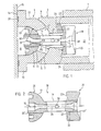
- Fig. 1 denotes a partially shown cylinder, in which a piston 3 is guided in a cylinder bore 2.
- the piston 3 is acted upon by a pressure medium at one end, not shown, while the other end 4 has a concave, spherical zone-shaped sliding surface on the end face, on which a slide shoe 6 with a convex spherical zone-shaped surface 7 is mounted.
- the slide shoe 6 has a cavity 8, which has a radius R1 in its base merging into a concave, spherical zone-shaped surface 9, the center of which 10 lies in the cavity 8.
- the convex, spherical zone-shaped surface 7 of the sliding block 6 with a radius R2 also has the same spherical center 10.
- the wall 12 of the sliding block 6 has a hollow spherical shape which merges into a flange 13, the end face 14 of which forms a sliding surface which is supported on a support surface 15 (not shown in more detail).
- the end face 14 of the slide shoe 6 and the support surface 15 have a relative movement to one another, the support surface 15 being fixed and the end face 14 of the slide shoe 6 rotating or vice versa the support surface 15 rotating and the end face 14 of the slide shoe 6 being stationary, depending on which one It is a type of piston unit. If the cylinder 1 rotates, the end face 14 of the sliding block 6 moves on the stationary support surface 15, as is the case with axial piston units with a rotating cylinder. However, the axial piston unit can also have a stationary cylinder 1, so that in this case the support surface 15 rotates.
- a passage 16 is provided in the wall 12 thereof, through which a coupling member 18 protrudes.
- the coupling member 18 is composed of a shaft part 19 and two joint heads 20, 21 arranged at its ends.
- the head 20 has a spherical shape with a spherical zone-shaped surface 11.
- the head 20 is firmly connected to the shaft part 19, for example by means of a threaded connection.
- the coupling member 18 can also be composed in a different way, as shown in FIG. 2.
- the joint head 20 located in the sliding block 6 is integrally connected to the shaft part 19 and is accordingly a single part.
- the coupling member 18 can also be made in three parts, the two rod ends 20, 21 being firmly connected to the shaft part 19, for example by threaded connections 20 ', 21'.
- the joint head 21 is also formed in two parts, a plate 32 having the concave spherical zone 23 being arranged on the side of the joint head 21 directed against the joint head 20. Since the rod end 21 has no further sliding function, it is sufficient if the plate 32 is made of a material which has particularly favorable sliding properties and high abrasion resistance, e.g. B. from a heat-treated, in particular alloyed steel, from a bronze-coated steel or entirely of bronze. If the joint head 21 and also the joint head 20 consist of one piece, the same considerations apply to the formation of the concave spherical zone 23 and the convex, spherical zone-shaped sliding surface 11 as for the formation of the plate 32.
- a material which has particularly favorable sliding properties and high abrasion resistance e.g. B. from a heat-treated, in particular alloyed steel, from a bronze-coated steel or entirely of bronze.
- the head 21 lies in the interior 22 of the hollow piston 3 and has a cylindrical shape which has the shape of a concave spherical zone on the side 23 facing the sliding shoe 6.
- the spherical zone 23 lies on a convex spherical zone 24 which is arranged at the bottom of the interior 22 of the piston 3.
- the ball zone 24 can, see the lower part of FIG. 1, be formed as an integral part of the piston 3. Or it can, see the upper half of FIG. 1, be produced as a separate part 25 with a flat underside 26 be placed on the in this case flat floor 27 in the interior 22 of the piston 3.
- the radius of curvature R3 of the two spherical zones 23, 24 expediently has the same spherical center 10 as the radii of curvature of the spherical zone-shaped surfaces 5, 7 and 9, 11.
- the entire length of the coupling member 18 is provided with a bore 28 through which the pressure medium located in the interior 22 of the piston 3 is guided into the cavity 8 and from there can be used for the supply of pressure fields 29 in the end face 24.
- a transverse bore 30 is arranged in the shaft part 19. This is connected to the longitudinal bore 28 and enables the introduction of the pressure medium into the passage 17 in the wall 12 of the sliding block 6 and into the bore 31 provided in the bottom of the piston 3. This causes all three sliding surfaces 5, 7; 9, 11 and 23, 25 acted upon by the pressure medium.
Abstract
Description
Die Erfindung betrifft eine Kolbeneinrichtung für eine Kolbeneinheit, insbesondere Hydraulikpumpe oder Hydraulikmotor mit mindestens einem in einem Zylinder geführten Kolben, welcher an der einen Stirnseite von einem Druckmedium beaufschlagt und an der andern Stirnseite mit einem über ein Kugelgelenk zusammenwirkenden Gleitschuh versehen ist, sowie über den Gleitschuh auf eine Stützfläche abgestützt ist, wobei der Kolben und der Gleitschuh durch ein mit einer Längsbohrung versehenes Kupplungsglied miteinander verbunden und zusammengehalten sind, welches an seinen Enden mit je einem Gelenkkopf versehen ist, der als Teil je eines im Innern des Kolbens und des Gleitschuhs angeordneten Kupplungs-Kugelgelenkes ausgebildet ist. Der Anwendungsbereich solcher Kolbeneinrichtungen erstreckt sich vor allem auf das Gebiet von Kolbeneinheiten, die als Kraft- oder Arbeitsmaschine verwendet werden. Das Arbeitsmittel ist hierbei ein unter Druck stehendes Gas, beispielweise Luft, oder ein unter Druck stehendes Fluid, beispielsweise ein Hydrauliköl.The invention relates to a piston device for a piston unit, in particular a hydraulic pump or hydraulic motor with at least one piston guided in a cylinder, which is acted upon by a pressure medium on one end face and is provided on the other end face with a sliding shoe interacting via a ball joint, and via the sliding shoe is supported on a support surface, the piston and the sliding block being connected and held together by a coupling member provided with a longitudinal bore, which is provided at its ends with an articulated head, which is part of a coupling arranged inside the piston and the sliding block -Ball joint is formed. The area of application of such piston devices extends above all to the area of piston units which are used as an engine or machine. The working medium is a pressurized gas, for example air, or a pressurized fluid, for example a hydraulic oil.
Kolbeneinrichtungen für solche Kolbeneinheiten sind in verschiedenen Ausführungen bekannt. Bei einer bekannten Ausführungsform (US-PS 4 454 802) ist der in einer Zylinderbohrung geführte Kolben stirnseitig über ein Kugelgelenk an einem Gleitschuh abgestützt. Der Gleitschuh seinerseits ist auf einer Stützfläche abgestützt, wobei der Gleitschuh und die Stützfläche sich relativ zueinander bewegen.Piston devices for such piston units are known in various designs. In a known embodiment (US Pat. No. 4,454,802), the piston guided in a cylinder bore is supported on the end face via a ball joint on a sliding shoe. The slide shoe in turn is supported on a support surface, the slide shoe and the support surface moving relative to one another.
Der Kolben und der Gleitschuh sind miteinander durch ein Kupplungsglied verbunden, welches an seinen Enden gegeneinandergerichtete kugelzonenförmige Köpfe aufweist, deren Kugelflächen mit im Innern des Kolbens und des Gleitschuhs angeordneten konkaven Kugelflächen zusammenwirken, so dass der Kolben und der Gleitschuh zusammengehalten werden. Da während des Betriebes einer solchen Kolbeneinheit Relativbewegungen zwischen dem Gleitschuh und dem Kolben und damit im Kugelgelenk auftreten, ist es erforderlich, dass das Kupplungsglied eine solche Bewegung erlaubt. Nun ist zwar bei der bekannten Ausführungsform eine solche Bewegung möglich, jedoch bewirken die beiden entgegengesetzt gerichteten kugelzonenförmigen Köpfe, dass Klemmwirkungen oder auch Spiel in den Gelenkflächen des Kupplungsgliedes auftreten können, die zu Beschädigungen der Oberfläche der Gleitflächen führen können.The piston and the sliding block are connected to one another by a coupling member which has spherical zone-shaped heads at its ends, the spherical surfaces of which interact with concave spherical surfaces arranged inside the piston and the sliding block, so that the piston and the sliding block are held together. Since relative movements occur between the sliding shoe and the piston and thus in the ball joint during the operation of such a piston unit, it is necessary for the coupling member to permit such a movement. Such a movement is now possible in the known embodiment, but the two oppositely directed spherical-zone-shaped heads cause clamping effects or play in the articulated surfaces of the coupling member, which can damage the surface of the sliding surfaces.
Eine weitere bekannte Ausführungsform einer Kolbeneinrichtung (GB-PS 1 357 995) weist eine Kolben-Gleitschuhkonstruktion auf, bei welcher im Gegensatz zu der vorstehend beschriebenen Ausführungsform der Kolben stirnseitig eine konvexe Kugelfläche und der Gleitschuh eine konkave Gelenkfläche aufweist. Zudem weist das Kupplungsglied nur an einem Ende eine kuglig ausgebildete Gelenkfläche auf, während das andere Ende fest mit dem Gleitschuh verbunden ist. Nachteilig ist jedoch bei dieser Ausführungsform die feste Verbindung zwischen dem Gleitschuh und dem Kupplungselement. Dadurch treten zusätzliche Beanspruchungen und/oder Klemmwirkungen in den Gelenkflächen auf, die zu Beschädigungen führen können.Another known embodiment of a piston device (GB-PS 1 357 995) has a piston sliding shoe construction in which, in contrast to the embodiment described above, the piston has a convex spherical surface on the end face and the sliding shoe has a concave joint surface. In addition, the coupling member has a spherical joint surface at only one end, while the other end is firmly connected to the sliding block. However, the disadvantage of this embodiment is the fixed connection between the sliding shoe and the coupling element. As a result, additional stresses and / or clamping effects occur in the joint surfaces, which can lead to damage.
Die Erfindung betrifft ebenfalls eine Kolbeneinrichtung, bei welcher der Kolben und der Gleitschuh über ein Kugelgelenk zusammenwirken und der Kolben und der Gleitschuh durch ein Kupplungsglied miteinander verbunden sind.The invention also relates to a piston device in which the piston and the sliding block interact via a ball joint and the piston and the sliding block are connected to one another by a coupling member.
Aufgabe der Erfindung ist es, eine Kolbeneinrichtung der eingangs beschriebenen Art so weiterauszugestalten, dass die Relativbewegung zwischen dem Kolben und dem Gleitschuh klemmfrei und spielfrei erfolgen kann.The object of the invention is to further develop a piston device of the type described at the outset in such a way that the relative movement between the piston and the sliding block can take place without jamming and without play.
Diese Aufgabe wird gemäss der Erfindung dadurch gelöst, dass die Kupplungs-Kugelgelenke im Kolben und im Gleitschuh Flächen mit Krümmungsradien aufweisen, welche gleichsinnig gewölbten Kugelflächen dieser Kugelgelenke zugeordnet sind und denselben Krümmungsmittelpunkt aufweisen. Zweckmässig weist das Kugelgelenk zwischen der andern Stirnseite des Kolbens und dem Gleitschuh einen Krümmungsradius mit demselben Krümmungsmittelpunkt wie die Krümmungsradien der Kugelgelenke an dem Ende des Kupplungsgliedes auf. Bei dieser Ausführung sind zwischen dem Kolben, dem Gleitschuh und dem Kupplungsglied drei Krümmungsradien von Kugelflächen vorhanden, die alle dasselbe Kugelzentrum aufweisen.This object is achieved according to the invention in that the coupling ball joints in the piston and in the sliding shoe have surfaces with radii of curvature which are assigned spherical surfaces of the same direction to these ball joints and have the same center of curvature. The ball joint expediently has a radius of curvature between the other end face of the piston and the sliding shoe with the same center of curvature as the radius of curvature of the ball joints at the end of the coupling member. In this embodiment, three radii of curvature of spherical surfaces are present between the piston, the sliding block and the coupling member, all of which have the same spherical center.
Ein Ausführungsbeispiel der Erfindung ist in der Zeichnung dargestellt und nachfolgend beschrieben. Es zeigen:
- Fig. 1 einen Längsschnitt einer Kolbeneinrichtung, wie sie für eine Kolbeneinheit, insbesondere Hydraulik-Pumpen und -Motoren, Verwendung finden kann, und
- Fig. 2 einen Längsschnitt durch eine Variante des in Fig. 1 dargestellten Kupplungsgliedes.
- Fig. 1 shows a longitudinal section of a piston device, as it can be used for a piston unit, in particular hydraulic pumps and motors, and
- Fig. 2 shows a longitudinal section through a variant of the coupling member shown in Fig. 1.
In Fig. 1 ist mit 1 ein teilweise dargestellter Zylinder bezeichnet, in welchem in einer Zylinderbohrung 2 ein Kolben 3 geführt ist. Der Kolben 3 ist an dem einen, nicht dargestellten Ende durch ein Druckmedium beaufschlagt, während das andere Ende 4 stirnseitig eine konkave, kugelzonenförmige Gleitfläche aufweist, auf welcher ein Gleitschuh 6 mit einer konvexen kugelzonenförmigen Fläche 7 gelagert ist.In Fig. 1, 1 denotes a partially shown cylinder, in which a
Der Gleitschuh 6 weist einen Hohlraum 8 auf, welcher mit einem Radius R1 in seinem Grund in eine konkave, kugelzonenförmige Fläche 9 übergeht, deren Kugelzentrum 10 im Hohlraum 8 liegt. Auch die konvexe, kugelzonenförmige Fläche 7 des Gleitschuhs 6 mit einem Radius R2 weist dasselbe Kugelzentrum 10 auf. Zwischen diesen beiden kugelzonenförmigen Flächen 5, 7 weist die Wand 12 des Gleitschuhs 6 eine hohlkugelförmige Gestalt auf, die in einen Flansch 13 übergeht, dessen Stirnseite 14 eine Gleitfläche bildet, die auf einer nicht näher dargestellten Stützfläche 15 abgestützt ist. Die Stirnseite 14 des Gleitschuhs 6 und die Stützfläche 15 weisen zueinander eine Relativbewegung auf, wobei die Stützfläche 15 fest und die Stirnseite 14 des Gleitschuhs 6 rotierend oder umgekehrt die Stützfläche 15 rotierend und die Stirnseite 14 des Gleitschuhs 6 ortsfest ist, je nachdem, um welchen Typ einer Kolbeneinheit es sich handelt. Rotiert der Zylinder 1, bewegt sich die Stirnseite 14 des Gleitschuhs 6 auf der ortsfesten Stützfläche 15, wie dies bei Axialkolbeneinheiten mit rotierendem Zylinder der Fall ist. Die Axialkolbeneinheit kann jedoch auch einen ortsfesten Zylinder 1 aufweisen, so dass sich in diesem Fall die Stützfläche 15 dreht.The
Im Gleitschuh 6 ist in dessen Wand 12 ein Durchgang 16 vorgesehen, durch welchen ein Kupplungsglied 18 ragt. Das Kupplungsglied 18 setzt sich aus einem Schaftteil 19 und zwei an dessen Enden angeordneten Gelenkköpfen 20, 21 zusammen. Der Kopf 20 weist eine kugelige Form mit einer kugelzonenförmigen Fläche 11 auf. Der Kopf 20 ist mit dem Schaftteil 19 fest verbunden, beispielsweise durch eine Gewindeverbindung.In the
Das Kupplungsglied 18 kann jedoch auch in anderer Weise zusammengesetzt sein, wie dies in Fig. 2 dargestellt ist. Gemäss dem obern Teil dieser Figur ist der im Gleitschuh 6 liegende Gelenkkopf 20 mit dem Schaftteil 19 integral verbunden und ist demgemäss ein einziger Teil. In diesem Fall ist es erforderlich, den im Kolben 3 liegenden Gelenkkopf 21 als separaten Teil auszubilden und ihn in geeigneter Weise mit dem Schaftteil 19 zu verbinden, z. B. durch eine Gewindeverbindung 21′.However, the
Wie aus dem untern Teil von Fig. 2 ersichtlich ist, kann das Kupplungsglied 18 auch dreiteilig ausgeführt sein, wobei die beiden Gelenkköpfe 20, 21 mit dem Schaftteil 19 fest verbunden sind, beispielsweise durch Gewindeverbindungen 20′, 21′.As can be seen from the lower part of Fig. 2, the
Im untern Teil von Fig. 2 ist zudem der Gelenkkopf 21 zweiteilig ausgebildet, wobei an der gegen den Gelenkkopf 20 gerichteten Seite des Gelenkkopfes 21 eine Platte 32 angeordnet ist, welche die konkave Kugelzone 23 aufweist. Da der Gelenkkopf 21 keine weitere Gleitfunktion ausübt, genügt es, wenn die Platte 32 aus einem Material hergestellt wird, das besonders günstige Gleiteigenschaften und eine hohe Abriebfestigkeit aufweist, z. B. aus einem wärmebehandelten, insbesondere legierten Stahl, aus einem bronzebeschichteten Stahl oder ganz aus Bronze. Besteht der Gelenkkopf 21 und auch der Gelenkkopf 20 aus einem Stück, gelten für die Ausbildung der konkaven Kugelzone 23 und der konvexen, kugelzonenförmigen Gleitfläche 11 die gleichen Ueberlegungen wie für die Ausbildung der Platte 32.In the lower part of FIG. 2, the
Der Kopf 21 liegt im Innenraum 22 des hohlen Kolbens 3 und weist Zylinderform auf, die an der, dem Gleitschuh 6 zugewandten Seite 23 die Form einer konkaven Kugelzone aufweist. Die Kugelzone 23 liegt auf einer konvexen Kugelzone 24, die am Grund des Innenraums 22 des Kolbens 3 angeordnet ist. Die Kugelzone 24 kann, siehe den untern Teil von Fig. 1, als integrales Teil des Kolbens 3 ausgebildet sein. Oder sie kann, siehe die obere Hälfte von Fig. 1, als separater Teil 25 mit einer ebenen Unterseite 26 hergestellt werden, der auf den in diesem Fall ebenen Boden 27 im Innenraum 22 des Kolben 3 gelegt wird. Zweckmässig weist der Krümmungsradius R3 der beiden Kugelzonen 23, 24 dasselbe Kugelzentrum 10 auf wie die Krümmungsradien der kugelzonenförmigen Flächen 5, 7 und 9, 11.The
Das Kupplungsglied 18 ist in seiner ganzen Länge mit einer Bohrung 28 versehen, durch welche das im Innenraum 22 des Kolbens 3 befindliche Druckmedium in den Hohlraum 8 geleitet und von dort für die Speisung von Druckfeldern 29 in der Stirnseite 24 verwendet werden kann. Im Schaftteil 19 ist eine Querbohrung 30 angeordnet. Diese steht mit der Längsbohrung 28 in Verbindung und ermöglicht die Einleitung des Druckmediums in den Durchgang 17 in der Wand 12 des Gleitschuhs 6 und in die im Boden des Kolbens 3 vorgesehene Bohrung 31. Dadurch werden alle drei Gleitflächen 5, 7; 9, 11 und 23, 25 durch das Druckmedium beaufschlagt. Da die Krümmungsradien dieser drei Gleitflächen das gleiche Kugelzentrum 10 aufweisen, sind bei Bewegungen zwischen dem Kolben 3 und dem Gleitschuh 6 drei Gleitflächen vorhanden, die ein klemmfreies Verschieben des Kupplungsgliedes 18 gegenüber dem Kolben 3 und dem Gleitschuh 6 ermöglichen. Dadurch wird eine Beschädigung der Gleitflächen zuverlässig vermieden.The entire length of the
Für den Kolben 3, den Gleitschuh 6, den separaten Teil 25 und die Stützfläche 15 gelten bezüglich der Materialauswahl dieselben Ueberlegungen, wie sie vorstehend für das Kupplungsglied 18 gemacht wurden. Im Hinblick auf die verhältnismässig hohen Flächenpressungen die an den verschiedenen Gleitflächen auftreten, muss eine Materialkombination gewählt werden, die günstige Reibeigenschaften und Abriebfestigkeit aufweist. Günstig ist z.B. an den vorhandenen Gleitflächen eine Kombination mit Bronce für die eine Gleitfläche und wärmebehandelter legierter Stahl für die andere Gleitfläche.For the
Claims (7)
Priority Applications (1)
| Application Number | Priority Date | Filing Date | Title |
|---|---|---|---|
| AT89104147T ATE99387T1 (en) | 1988-05-10 | 1989-03-09 | PISTON DEVICE FOR A PISTON UNIT. |
Applications Claiming Priority (2)
| Application Number | Priority Date | Filing Date | Title |
|---|---|---|---|
| CH1769/88A CH678091A5 (en) | 1988-05-10 | 1988-05-10 | |
| CH1769/88 | 1988-05-10 |
Publications (3)
| Publication Number | Publication Date |
|---|---|
| EP0341390A2 true EP0341390A2 (en) | 1989-11-15 |
| EP0341390A3 EP0341390A3 (en) | 1990-09-05 |
| EP0341390B1 EP0341390B1 (en) | 1993-12-29 |
Family
ID=4218159
Family Applications (1)
| Application Number | Title | Priority Date | Filing Date |
|---|---|---|---|
| EP89104147A Expired - Lifetime EP0341390B1 (en) | 1988-05-10 | 1989-03-09 | Piston device for a piston unit |
Country Status (5)
| Country | Link |
|---|---|
| US (1) | US5099750A (en) |
| EP (1) | EP0341390B1 (en) |
| AT (1) | ATE99387T1 (en) |
| CH (1) | CH678091A5 (en) |
| DE (1) | DE58906516D1 (en) |
Cited By (2)
| Publication number | Priority date | Publication date | Assignee | Title |
|---|---|---|---|---|
| WO2009103762A1 (en) * | 2008-02-22 | 2009-08-27 | Polysius Ag | Force transfer system comprising a hydraulic cylinder and a thrust bearing |
| CN105057024A (en) * | 2015-07-20 | 2015-11-18 | 成都大宏立机器股份有限公司 | Ball force transmission mechanism of high-pressure roller mill |
Families Citing this family (5)
| Publication number | Priority date | Publication date | Assignee | Title |
|---|---|---|---|---|
| US5445030A (en) * | 1993-10-06 | 1995-08-29 | Wyle Laboratories | Spherical coupling |
| US6116990A (en) * | 1997-07-25 | 2000-09-12 | Applied Materials, Inc. | Adjustable low profile gimbal system for chemical mechanical polishing |
| EP1605096B1 (en) * | 2004-06-11 | 2007-09-05 | Metso Paper, Inc. | Shoe press |
| US20120240896A1 (en) * | 2011-03-21 | 2012-09-27 | Tadeusz Slawinski | Internal Combustion Engine with Rotating Cylinder Block |
| EP3597914B8 (en) * | 2018-07-20 | 2022-05-04 | Masterflex, LLC | Tubing retention mechanism usable with a peristaltic pump |
Citations (4)
| Publication number | Priority date | Publication date | Assignee | Title |
|---|---|---|---|---|
| US2483856A (en) * | 1945-03-08 | 1949-10-04 | Cash A W Co | Hydraulic mechanism |
| DE968651C (en) * | 1940-09-10 | 1958-06-04 | Schlafhorst & Co W | Swash plate engine |
| DE2163158A1 (en) * | 1970-12-19 | 1972-07-13 | Salzmann W | Crank drive for reciprocating piston machines |
| DE2915239A1 (en) * | 1979-04-14 | 1980-10-23 | Wepuko Hydraulik Gmbh & Co Pum | Radial plunger high pressure pump - has shoes bearing against plungers without being positively coupled to them |
Family Cites Families (4)
| Publication number | Priority date | Publication date | Assignee | Title |
|---|---|---|---|---|
| US2901979A (en) * | 1953-07-24 | 1959-09-01 | North American Aviation Inc | Hydraulic unit with improved piston assembly |
| US3319575A (en) * | 1965-06-14 | 1967-05-16 | Sundstrand Corp | Piston |
| DE2118712A1 (en) * | 1971-04-17 | 1972-11-16 | Robert Bosch Gmbh, 7000 Stuttgart | Piston sliding shoe element for hydrostatic piston machines |
| FR2492469B1 (en) * | 1980-10-28 | 1985-10-31 | Poclain Hydraulics Sa | PISTON ASSEMBLY FOR A FLUID MECHANISM WITH A REACTION PLATE AND ITS SLIDING PAD |
-
1988
- 1988-05-10 CH CH1769/88A patent/CH678091A5/de not_active IP Right Cessation
-
1989
- 1989-03-09 DE DE89104147T patent/DE58906516D1/en not_active Expired - Fee Related
- 1989-03-09 AT AT89104147T patent/ATE99387T1/en active
- 1989-03-09 EP EP89104147A patent/EP0341390B1/en not_active Expired - Lifetime
-
1990
- 1990-11-13 US US07/614,184 patent/US5099750A/en not_active Expired - Fee Related
Patent Citations (4)
| Publication number | Priority date | Publication date | Assignee | Title |
|---|---|---|---|---|
| DE968651C (en) * | 1940-09-10 | 1958-06-04 | Schlafhorst & Co W | Swash plate engine |
| US2483856A (en) * | 1945-03-08 | 1949-10-04 | Cash A W Co | Hydraulic mechanism |
| DE2163158A1 (en) * | 1970-12-19 | 1972-07-13 | Salzmann W | Crank drive for reciprocating piston machines |
| DE2915239A1 (en) * | 1979-04-14 | 1980-10-23 | Wepuko Hydraulik Gmbh & Co Pum | Radial plunger high pressure pump - has shoes bearing against plungers without being positively coupled to them |
Cited By (4)
| Publication number | Priority date | Publication date | Assignee | Title |
|---|---|---|---|---|
| WO2009103762A1 (en) * | 2008-02-22 | 2009-08-27 | Polysius Ag | Force transfer system comprising a hydraulic cylinder and a thrust bearing |
| JP2011512253A (en) * | 2008-02-22 | 2011-04-21 | ポリシウス アクチェンゲゼルシャフト | Power transmission system comprising a hydraulic cylinder and a thrust bearing |
| US8398008B2 (en) | 2008-02-22 | 2013-03-19 | Polysius Ag | Force transfer system comprising a hydraulic cylinder and a thrust bearing |
| CN105057024A (en) * | 2015-07-20 | 2015-11-18 | 成都大宏立机器股份有限公司 | Ball force transmission mechanism of high-pressure roller mill |
Also Published As
| Publication number | Publication date |
|---|---|
| EP0341390A3 (en) | 1990-09-05 |
| EP0341390B1 (en) | 1993-12-29 |
| US5099750A (en) | 1992-03-31 |
| ATE99387T1 (en) | 1994-01-15 |
| CH678091A5 (en) | 1991-07-31 |
| DE58906516D1 (en) | 1994-02-10 |
Similar Documents
| Publication | Publication Date | Title |
|---|---|---|
| DE2620523A1 (en) | AXIAL PISTON MACHINE ACCORDING TO THE INCLINED DISC PRINCIPLE | |
| DE2106923A1 (en) | Internal combustion engine pistons | |
| DE2305857A1 (en) | PISTONS FOR COMBUSTION MACHINERY | |
| DE3136110C2 (en) | Articulated coupling | |
| CH666094A5 (en) | CROSS HEAD PIN BEARINGS FOR PISTON MACHINES. | |
| EP0341390B1 (en) | Piston device for a piston unit | |
| DD202597A5 (en) | MECHANISM FOR THE CONVERSION OF A TURNING MOVEMENT IN A STRAIGHT-LOOKING MOVEMENT | |
| EP0752530B1 (en) | Reciprocating piston machine with swash plate mechanism | |
| EP0705968A1 (en) | Piston for internal combustion engine | |
| DE882932C (en) | Spaciously working reciprocating gear | |
| DE2158690A1 (en) | SLIDER FOR PISTON MACHINES | |
| DE3800031A1 (en) | Axial piston machine developing torque on the cam plate | |
| DE3140921A1 (en) | PISTON AND SLIDE SHOE COMPREHENSIVE ARRANGEMENT FOR HYDRAULIC WORKING EQUIPMENT | |
| DE3206152A1 (en) | CROSS HEAD OF A PISTON MACHINE | |
| DE2003851A1 (en) | Hydraulic pump or motor of the axial piston type | |
| DE3039382A1 (en) | LIGHT TACH PISTON FOR COMBUSTION ENGINES | |
| DE3641783A1 (en) | Piston-con-rod joint for the transmission of tensile and compressive forces | |
| DE2641158A1 (en) | Axial pistn lubricating pump - has pistons with concave spherical faces on convex hollow joints driven by ball jointed shaft | |
| DE1653613C3 (en) | Driving device for the connecting rods of a swash plate axial piston machine | |
| EP1287232B1 (en) | Axial piston engine | |
| DE69924287T2 (en) | PLEUEL PISTON UNIT | |
| DE3540085A1 (en) | PISTON FOR INTERNAL COMBUSTION ENGINES | |
| AT380819B (en) | SWIVEL JOINT FOR MANIPULATORS | |
| DE3641782A1 (en) | Piston-con-rod joint for the transmission of tensile and compressive forces | |
| DE1176954B (en) | Infinitely variable hydrostatic power transmission |
Legal Events
| Date | Code | Title | Description |
|---|---|---|---|
| PUAI | Public reference made under article 153(3) epc to a published international application that has entered the european phase |
Free format text: ORIGINAL CODE: 0009012 |
|
| AK | Designated contracting states |
Kind code of ref document: A2 Designated state(s): AT BE DE ES FR GB GR IT LU NL SE |
|
| PUAL | Search report despatched |
Free format text: ORIGINAL CODE: 0009013 |
|
| AK | Designated contracting states |
Kind code of ref document: A3 Designated state(s): AT BE DE ES FR GB GR IT LU NL SE |
|
| 17P | Request for examination filed |
Effective date: 19910212 |
|
| 17Q | First examination report despatched |
Effective date: 19920703 |
|
| GRAA | (expected) grant |
Free format text: ORIGINAL CODE: 0009210 |
|
| ITF | It: translation for a ep patent filed |
Owner name: BARZANO' E ZANARDO MILA |
|
| AK | Designated contracting states |
Kind code of ref document: B1 Designated state(s): AT BE DE ES FR GB GR IT LU NL SE |
|
| PG25 | Lapsed in a contracting state [announced via postgrant information from national office to epo] |
Ref country code: NL Effective date: 19931229 Ref country code: GR Free format text: LAPSE BECAUSE OF FAILURE TO SUBMIT A TRANSLATION OF THE DESCRIPTION OR TO PAY THE FEE WITHIN THE PRESCRIBED TIME-LIMIT Effective date: 19931229 Ref country code: ES Free format text: THE PATENT HAS BEEN ANNULLED BY A DECISION OF A NATIONAL AUTHORITY Effective date: 19931229 Ref country code: BE Effective date: 19931229 |
|
| REF | Corresponds to: |
Ref document number: 99387 Country of ref document: AT Date of ref document: 19940115 Kind code of ref document: T |
|
| REF | Corresponds to: |
Ref document number: 58906516 Country of ref document: DE Date of ref document: 19940210 |
|
| ET | Fr: translation filed | ||
| PG25 | Lapsed in a contracting state [announced via postgrant information from national office to epo] |
Ref country code: AT Effective date: 19940309 |
|
| PG25 | Lapsed in a contracting state [announced via postgrant information from national office to epo] |
Ref country code: LU Free format text: LAPSE BECAUSE OF NON-PAYMENT OF DUE FEES Effective date: 19940331 |
|
| GBT | Gb: translation of ep patent filed (gb section 77(6)(a)/1977) |
Effective date: 19940427 |
|
| NLV1 | Nl: lapsed or annulled due to failure to fulfill the requirements of art. 29p and 29m of the patents act | ||
| PLBE | No opposition filed within time limit |
Free format text: ORIGINAL CODE: 0009261 |
|
| STAA | Information on the status of an ep patent application or granted ep patent |
Free format text: STATUS: NO OPPOSITION FILED WITHIN TIME LIMIT |
|
| 26N | No opposition filed | ||
| EAL | Se: european patent in force in sweden |
Ref document number: 89104147.7 |
|
| PGFP | Annual fee paid to national office [announced via postgrant information from national office to epo] |
Ref country code: GB Payment date: 20010214 Year of fee payment: 13 |
|
| PGFP | Annual fee paid to national office [announced via postgrant information from national office to epo] |
Ref country code: SE Payment date: 20010305 Year of fee payment: 13 |
|
| PGFP | Annual fee paid to national office [announced via postgrant information from national office to epo] |
Ref country code: FR Payment date: 20010313 Year of fee payment: 13 Ref country code: DE Payment date: 20010313 Year of fee payment: 13 |
|
| REG | Reference to a national code |
Ref country code: GB Ref legal event code: IF02 |
|
| PG25 | Lapsed in a contracting state [announced via postgrant information from national office to epo] |
Ref country code: GB Free format text: LAPSE BECAUSE OF NON-PAYMENT OF DUE FEES Effective date: 20020309 |
|
| PG25 | Lapsed in a contracting state [announced via postgrant information from national office to epo] |
Ref country code: SE Free format text: LAPSE BECAUSE OF NON-PAYMENT OF DUE FEES Effective date: 20020310 |
|
| PG25 | Lapsed in a contracting state [announced via postgrant information from national office to epo] |
Ref country code: DE Free format text: LAPSE BECAUSE OF NON-PAYMENT OF DUE FEES Effective date: 20021001 |
|
| EUG | Se: european patent has lapsed |
Ref document number: 89104147.7 |
|
| GBPC | Gb: european patent ceased through non-payment of renewal fee |
Effective date: 20020309 |
|
| PG25 | Lapsed in a contracting state [announced via postgrant information from national office to epo] |
Ref country code: FR Free format text: LAPSE BECAUSE OF NON-PAYMENT OF DUE FEES Effective date: 20021129 |
|
| REG | Reference to a national code |
Ref country code: FR Ref legal event code: ST |
|
| PG25 | Lapsed in a contracting state [announced via postgrant information from national office to epo] |
Ref country code: IT Free format text: LAPSE BECAUSE OF NON-PAYMENT OF DUE FEES Effective date: 20050309 |