EP0341384A2 - Dispositif de mouillage pour presse à imprimer commande par microprocesseur - Google Patents
Dispositif de mouillage pour presse à imprimer commande par microprocesseur Download PDFInfo
- Publication number
- EP0341384A2 EP0341384A2 EP89103408A EP89103408A EP0341384A2 EP 0341384 A2 EP0341384 A2 EP 0341384A2 EP 89103408 A EP89103408 A EP 89103408A EP 89103408 A EP89103408 A EP 89103408A EP 0341384 A2 EP0341384 A2 EP 0341384A2
- Authority
- EP
- European Patent Office
- Prior art keywords
- damprate
- data
- control
- press
- value
- Prior art date
- Legal status (The legal status is an assumption and is not a legal conclusion. Google has not performed a legal analysis and makes no representation as to the accuracy of the status listed.)
- Granted
Links
Images


Classifications
-
- B—PERFORMING OPERATIONS; TRANSPORTING
- B41—PRINTING; LINING MACHINES; TYPEWRITERS; STAMPS
- B41F—PRINTING MACHINES OR PRESSES
- B41F33/00—Indicating, counting, warning, control or safety devices
- B41F33/0054—Devices for controlling dampening
Definitions
- the present invention relates to offset printing presses and, particularly, to the electronic control of such presses.
- Web offset printing presses have gained widespread acceptance by metropolitan daily as well as weekly newspapers. Such presses produce a quality black and white or color product at very high speeds. To maintain image quality, a number of printing functions must be controlled very precisely as the press is operating. These include the control of press speed, the control of color register, the control of ink flow and the control of dampening water.
- the lithographic plate is mounted to a rotating plate cylinder.
- the ink is injected onto an ink pickup roller and from there it is conveyed through a series of transfer rollers which spread the ink uniformly along their length and transfer the ink to the image areas of the rotating plate.
- dampening water is applied to a fountain roller and is conveyed through one or more transfer rollers to the non-image areas of the rotating plate cylinder.
- the plate cylinder rotates in contact with a blanket cylinder which transfers the ink image from the plate cylinder to the moving paper web.
- the amount of ink and dampening water supplied to the plate cylinder is directly proportional to the press speed.
- the plate cylinder and blanket cylinder transfer ink and water to the paper web at a higher rate, and the inking and dampening systems must, therefore, supply more ink and water.
- this relationship is not linear and that the rate at which ink and dampening water is applied follows a complex rate curve which is unique to each press and may be unique to each run on a press.
- the ink and water may be applied nonuniformly across the width of the ink pickup roller and the fountain roller in order to achieve uniform printing quality along the width of the web. If this is not done, there may be significant changes in the quality of the printed images across the width of the moving web.
- Prior press control systems have provided limited control over the rate at which dampening water has been applied as a function of press speed. These systems pulse the nozzles on the spraybar on and off at one of a plurality of selectable pulse rates. The particular pulse rate selected is determined by the press speed. The particular pulse rates and selection points between pulse rates is preset to follow the dampening rate curve of the press as closely as possible. There is no means for easily changing these values or for providing a continuous range of pulse rates which closely follow the rate curve. In addition, while the amount of dampening water applied by the spraybar can be adjusted over the width thereof, this is a manual adjustment which may only be made locally at a spraybar controller. Thus, if inconsistencies in print quality are observed over the width of the image, manual adjustments to the circuitry must be made at a local control panel.
- the present invention relates to a control system for an offset printing press and, particularly, to the control of a dampening system on such a press.
- the dampening control system of the present invention includes a communications link with the press control system that enables dampening control parameters, such as dampening rate curve data, flood request data and spraybar nozzle pulse width data, to be downloaded and acted upon.
- dampening control parameters such as dampening rate curve data, flood request data and spraybar nozzle pulse width data
- the pulse width applied to energize each spraybar nozzle is separately controlled by presettable counter means which can be changed by downloaded data while the press is running.
- the spraybar nozzles are energized by pulse rate means which produces pulses at a rate determined by calculation means that interpolates between the data points in the downloaded dampening rate curve.
- a general object of the invention is to provide a flexible dampening water control system which can be configured and adjusted by downloading data from a master work station or a local control panel.
- the dampening water control system includes a microprocessor which is programmed to carry out the various control functions using data which is stored in a read/write memory. The data stored in this memory can be changed by messages which are received from the master work station or the local control panel. As a result, the operating parameters of the dampening water control system can be easily altered even while the microprocessor is carrying out its control functions.
- a more specific object of the invention is to enable the dampening rate curve data which controls nozzle pulse rate as a function of press speed to be changed.
- the rate curve data which is used to calculate the nozzle pulse rate is stored in the read/write memory. This data may be easily changed by the microprocessor when new rate curve data is received from the master work station through the communications link.
- Yet another general object of the invention is to control the nozzle pulse rate such that it more accurately follows the dampening rate curve defined by the dampening rate curve data.
- the rate curve data provides discrete data points on the dampening rate curve which each relate a pulse rate to a press speed.
- the calculation means receives a press speed value from press speed feedback means and identifies the two data points which straddle this press speed value. Using the press speed, the calculation means interpolates between these two data points to determine the desired nozzle pulse rate which is then used to operate the pulse rate means.
- Yet another object of the invention is to enable the pulse widths of each spraybar nozzle to be separately controlled and easily adjusted.
- the desired pulse width of each nozzle is stored in the read/write memory and is output to the presettable counter associated with the spraybar nozzle.
- this stored pulse width data is altered in accordance with the downloaded information.
- the microprocessor then updates the appropriate presettable counters such that the altered nozzle pulse rates will be produced.
- Still another object of the invention is to control the flood function from the master work station.
- a flood timer value stored in the read/write memory is preset to a value indicated in the message.
- the flood timer value is decremented in response to signals from a real time clock means and during the indicated time interval the pulse widths of each controlled nozzle is incremented a preselected amount to increase the amount of dampening water applied to the plate cylinder.
- a more specific object of the invention is to provide a press speed feedback signal which is stored in the read/write memory for use by the calculation means.
- An incremental position feedback device produces a pulse for each increment of press motion.
- a counter is energized to count a preset number of incremental feedback pulses and a timer records the time interval required to receive the preset number of feedback pulses.
- the microprocessor periodically reads the timer value and converts it to a velocity which is stored n the read/write memory.
- Yet another object of the invention is to provide a spraybar nozzle control circuit which pulses the nozzles on at a commanded rate and which turns them off separately after commanded time intervals.
- a presettable counter is associated with each nozzle and can be separately configured to preset to a specific value each time the nozzles are pulsed on. These counters are operated to act as timers which expire to turn off their respective nozzles independently at times determined by their presettable values.
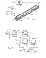
- a printing press is comprised of one or more printing units 10 which are controlled from a master work station 11.
- Each printing unit is linked to the master work station by a unit controller 12 which communicates through a local area network 13.
- the master work station 11 and the unit controllers 12 may send messages to each other through the network 13 to both control the operation of the press and to gather production information.
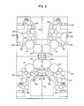
- each printing unit 10 is comprised of four units which are referred to as levels A, B, C and D and which are designated herein as units 10A, 10B, 10C and 10D.
- the units 10A-D are stacked one on top of the other and a web 15 passes upward through them for printing on one or both sides.
- the printing units 10 are configured for full color printing on both sides of the web, where the separate units 10A-D print the respective colors blue, red, yellow and black.
- each unit 10A-D includes two printing couples comprised of a blanket cylinder 20 and a plate cylinder 21.
- the web 15 passes between the blanket cylinders 20 in each unit for printing on both sides.
- Ink is applied to each plate cylinder 21 by a series of ink transfer rollers 22 which receive ink from an ink pickup roller 23.
- the ink transfer rollers 22 insure that the ink is distributed uniformly along their length and is applied uniformly to the rotating plate cylinder 21.
- each plate cylinder 21 is supplied with dampening water by a pair of dampener transfer rollers 24 and a dampener rider roller 25.
- a spray bar assembly 26 applies dampening water to each of the dampener rider rollers 25 as will now be described in more detail.
- each spray bar assembly 26 receives a supply of pressurized water from a water supply tank 27 through a pump 28 and solenoid valve 29.
- the spray bar assembly 26 includes eight nozzles 30 which each produce a flat, fan-shaped spray pattern of water when an associated solenoid valve 31 is energized.
- all eight solenoid valves 31 are energized, a thin line of water is sprayed along the entire length of the associated dampener rider roller 25.
- the solenoid valves 31 are pulsed on and off at a rate which is proportional to press speed so that the proper amount of dampening water is applied and transferred to the plate cylinder 21. It is also well known that means must be provided for separately adjusting the amount of water sprayed by each nozzle 30 to account for variations in the distribution of dampening water over the length of the plate cylinder 21.
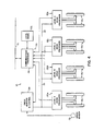
- each unit controller includes a communications processor 30 of the type disclosed in the above-cited U. S. Patent No. 4,667,323 which interfaces with the local area network 13.
- the communications processor 30 provides six serial communications channels 31 through which it can receive input messages for transmission on the network 13. Messages which are received through the network 13 by the communications processor 30 are distributed to the appropriate serial channel 30.
- the serial communications channels 30 employ a standard RS 422 protocol.
- each drink processor 35 is coupled to sensing devices and operating devices on a respective one of the levels A-D of the printing unit 10.
- each drink processor 35A-D produces output signals which control the solenoid valves 31 on the spray bars 26.
- the drink processors 35A-D also control the application of ink to the ink pickup rollers 23 and control color register, but these functions will not be described in any detail in this specification.
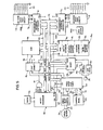
- each drink processor 35 is structured about a 23-bit address bus 40 and a 16-bit data bus 41 which are controlled by a 16-bit microprocessor 42.
- the microprocessor 42 is a model 68000 sold commercially by Motorola, Inc. which is operated by a 10 mHz clock 43.
- ROM read-only memory
- the microprocessor 42 addresses elements of the drink processor 35 through the address bus 40 and exchanges data with the addressed element through the data bus 41.
- the state of a read/write (R/W) control line 45 determines if data is read from the addressed element or is written to it.
- the addressable elements are integrated circuits which occupy a considerable address space.
- the chip enable circuit 46 is comprised of logic gates and three PAL16L8 programmable logic arrays sold commercially by Advanced Micro Devices, Inc. As is well known in the art, the chip enable circuit 46 is responsive to the address on the bus 40 and a control signal on a line 47 from the microprocessor 42 to produce a chip select signal for the addressed element. For example, the ROM 44 is enabled through a line 48 when a read cycle is executed in the address range SFOOOOO through $F7FFFF.
- Table A The address space occupied by each of the addressable elements in the drink processor 35 is given in Table A.
- a read/write random access memory (RAM) 50 stores the data structures which are employed to carry out these functions.
- these data structures include elements which are collectively referred to herein as a switch database 51, a control database 52, receive message buffers 49, and send message buffers 66.
- the switch database 51 indicates the status of various switches on the local control panels 53
- the control database 52 stores data indicative of press speed, nozzle pulse rate, and nozzle pulse width.
- the RAM 50 is enabled for a read or write cycle with the microprocessor 42 through a control line 54.
- the drink processor 35 is coupled to one of the serial channels 31 of the communications processor 30 by a dual universal asynchronous receiveritransmitter (DUART) 55.
- the DUART 55 is commercially available as an integrated circuit model 68681 from Motorola, Inc. It operates to convert message data written to the DUART 55 by the microprocessor 42 into a serial bit stream which is applied to the serial channel 31 by a line drive circuit 56 that is compatible with the RS 422 standard. Similarly, the DUART 55 will receive a serial bit stream through a line receiver 57 and convert it to a message that may be read by the microprocessor 42.
- the DUART 55 is driven by a 3. 6864 mHz clock produced by a crystal 58 and is enabled for either a read or write cycle through control line 59.
- the press speed feedback signal as well as signals from the local control panel 53 are input to the drink processor 35 through a programmable interface timer (PIT) 60.
- the PIT 60 is commercially available in integrated circuit form as the model 68230 from Motorola, Inc. It provides two 8-bit parallel ports which can be configured as either inputs or outputs and a number of separate input and output points. In the preferred embodiment, one of the ports is used to input switch signals from the control panel 53 through lines 60, and the second port is used to output indicator light signals to the control panel 53 through lines 61.
- the PIT 60 is enabled through control line 62 and its internal registers are selected by leads AO-A4 in the address bus 40.
- the PIT 60 includes a programmable timer/counter. This timer may be started and stopped when written to by the microprocessor 42 and it is incremented at a rate of 312.5 kHz by an internal clock driven by the 10 mHz clock 43. When the timer is started, a logic high pulse is also produced at an output 63 to a speed interfaces circuit 64. When the interface circuit 64 subsequently produces a pulse on input line 65, as will be described in detail below, the timer stops incrementing and a flag bit is set in the PIT 60 which indicates the timer has stopped. This flag bit is periodically read and checked by the microprocessor 42, and when set, the microprocessor 42 reads the timer value from the PIT 60 and uses it to calculate current press speed.
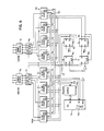
- the solenoid valves 31 on each spray bar assembly 26 are operated through a programmable interface controller (PIC) 70 or 72 and an associated solenoid interface circuit 71 or 73.
- PICs 70 and 72 are commercially available integrated circuits sold by Motorola, Inc. as the model 68230. Each includes a pair of 8-bit output registers as well as a single bit output indicated at 75 and 76. Each output register can be separately addressed and an 8-bit byte of data can be written thereto by the microprocessor 42. The two 8-bit bytes of output data are applied to the respective solenoid interface circuits 71 and 73.
- the solenoid valves 31 are turned on for a short time period each time a pulse is produced at the single bit output of the PICs 70 and 72. This output pulse is produced each time an internal timer expires, and the rate at which the timer expires can be set to a range of values by the microprocessor 42.
- the time period which each solenoid valve 31 remains energized is determined by the operation of the solenoid interface circuits 71 and 73, which in turn can be separately configured by writing values to the registers in the PICs 70 and 72.
- the rate at which the spray bars 26 are pulsed on is under control of the programs executed by the microprocessor 42, and the duration of the spray pulses from each nozzle 30 of the spray bars 26 can be separately controlled.
- the solenoid interface circuit 71 is shown in Fig 6. and it should be understood that the solenoid interface circuit 73 is virtually identical. Each includes a set of eight 8-bit binary counters 80 and a set of eight R/S flip-flops 81 and 82.
- the counters 80 are available in integrated circuit form as the 74LS592 from Texas Instruments, Inc. and they each include an internal 8-bit input register. This input register is loaded with an 8-bit binary number on output bus 83 when a pulse is applied to an RCK input of the counter 80.
- the RCK inputs of the eight counters 80 are connected to respective ones of the output terminals PBO-PB7 of the PIC 70, and the eight leads in the output bus 83 are driven by the output terminals PAO-PA7 of the PIC 70 through a buffer 84.
- any or all of the registers in the counters 80 can be loaded with a binary number on the PA output port of the PIC 70 by enabling the counter's RCK input with a"1" " on the corresponding lead of the PB output port.
- this circuitry is used to separately preset each 8-bit counter 80 so that the time interval which each of the solenoid valves 30 remains on can be separately controlled.
- an output pulse is produced at the PC3 output pin of the PIC 70 each time an internal timer 85 expires.
- the timer 85 is preset with a calculated current pulse rate value by the microprocessor 42.
- two phase displaced pulses are produced by a set of four D-type flip-flops 86-89.
- the Q output of flip-flop 87 sets the RS flip-flops 81 on the leading edge of one pulse and it presets four of the counters 80 with the values stored in their respective input registers. On the trailing edge of this first pulse, the U-output of the flip-flop 87 returns to a logic low which enables the same four counters to begin counting.
- the remaining four counters 80 and the R/S flip-flops 82 are operated in the same manner by the Q and Q outputs of the flip-flop 89.
- the only difference is that the operation of the flip-flop 89 is delayed by one-half the time period between successive pulses from the flip-flop 87.
- the eight counters 80 are incremented by 2 kHz clock pulses until they reach the all ones condition. At this point the output of the counter 80 goes to a logic low voltage and it resets the R/S flip-flop 81 or 82 to which it connects.
- the output of each R/S flip-flop 81 or 82 controls the operation of one of the solenoid valves 31 through power drivers 90 and 91 and, thus, each valve 31 is turned on when the flip-flops 81 and 82 are set, and they are each turned off as their associated counter 80 overflows and resets its R/S flip-flop.
- the outputs of the drivers 90 are connected to the first, third, fifth and seventh nozzle solenoids and the outputs of the drivers 91 are connected to the second, fourth, sixth and eighth nozzle solenoids.
- nozzles 1, 3, 5 and 7 are turned on each time a pulse is produced at PIC output terminal PC3 and nozzles 2, 4, 6 and 8 are turned on a short time interval later (i. e. greater than 5 milliseconds later).
- Each nozzle 30 is then turned off separately as their corresponding counters 80 overflow.
- the speed interface circuit 64 couples the digital incremented speed feedback signal received from the speed sensor 36 to the PIT 60.
- the speed sensor 36 produces a logic high voltage pulse for each incremental movement of the web through the printing unit.
- a magnetic sensor model 10001 available from Airpax Corporation is employed for this purpose, although any number of position feedback devices will suffice.
- the speed sensor's signal is applied to a line receiver 95 which produces a clean logic level signal that is applied to the input of a 4-bit binary counter 96.
- the counter 96 produces an output pulse each time sixteen feedback pulses are produced by the speed sensor 36.
- This overflow is applied to the clock terminal of a D-type flip-flop 97 which switches to a logic state determined by the logic state applied to its D input.
- the D input is in turn driven by a second flip-flop 98 which is controlled by the PCO output of the PIT 60 and the Q'output of flip-flop 97.
- the counter 96 again overflows to reset the flip-flop 97 and to thereby stop the timer 100 in the PIT 60.
- Input PC1 also goes low, and when read next by the microprocessor 42, it signals that a complete sample has been acquired and can be read from the PIT 60. The entire cycle may then be repeated by again writing a "1 " to the PCO output of the PIT 60.
- the speed feedback circuit of the present inventions offers a number of advantages.
- the error caused by a noise voltage spike on the input lines is effectively reduced to about one sixteenth the error that would result if speed were measured by sensing the feedback pulse rate directly.
- the microprocessor 42 is not burdened with a continuous monitoring of the speed feedback signal. Instead, when the system requires an updated sample of press speed, the microprocessor checks the PIT 60 and reads the latest value stored therein. It then initiates the taking of another sample and continues on with its many other tasks.
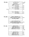
- the data structures which are employed by the preferred embodiment of the present invention to control the spraybars 26 are stored in the RAM 50. As indicated above, these data structures are collectively referred to as the switch database 51 and the control database 52. The structure of these two databases 51 and 52 are illustrated in Fig. 8 for one printing couple. Similar data is stored in the databases 51 and 53 for the other printing couple in the unit 10.
- the switch database 51 includes an image of the switch states on the local control panel 53 (Fig. 5).
- the operator depresses a "FLOOD" switch when extra dampening water is to be applied during startup. As will be described below, when this occurs, the dampening water flow rate is increase 25% for a preset time interval.
- a flood switch status word 120, a flood switch examine flag 121 and a flood timer value 122 are stored in the RAM 50.
- Flood switch status 120 is updated every 100 milliseconds as will be described below to reflect the current state of the control panel switch.
- the other two data structures are employed to recognize the flood request and implement the request for a preset time interval.
- dampening water is also increased.
- the status of this signal is stored at an autoflood switch status word 123, and as long as it is present, increased dampening water will be produced. And finally, the dampening system can be disabled by the operator and this event is stored at 124.
- switch database 51 A number of other data structures are contained in the switch database 51, but these pertain to the inkrate control system for the printing unit 10, and these will not be discussed in any detail in this specification.
- control status 125 indicates if the control is in the process of making a requested change ("change in progress") or if no changes have been requested ("idle").
- Control status 125 also includes a "changes not complete counter” which indicates at any time the number of controllable nozzles which are undergoing changes.
- a dampener mode word 126 indicates if the dampening system is in either manual or automatic mode. In the manual mode the dampening flow rate is set to a value indicated as unit trim 127, which can be manually altered from the master work station 11 or a local panel 53 (Fig. 1). In the automatic mode, the dampening water flow rate is calculated as a function of press speed in accordance with stored rate curve data 128 as will be described in more detail below.
- a flood request flag 129 is set when the flood function is being performed and an update flag 130 is set when a significant change in press speed has occurred or new rate curve data 128 has been down loaded from the master work station 11.
- the press speed is measured every 100 milliseconds and stored as the instantaneous press speed 131. If the instantaneous press speed 131 differs by more than t.5% from a processed press speed stored at 132, then the processed press speed 1 32 is updated with the newly measured value and the update flag 130 is set.
- the processed press speed 132 is used in combination with the rate curve data 128 to calculate a new dampening water flow rate when the dampening system is in the "AUTO" mode.
- This is converted to a pulse rate and is modified by a stored couple trim value 133 and increased further if the flood request flag 130 is set.
- the resulting current pulse rate value is stored at 134 and is output to the timer 85 in the PIC 70 (Fig. 6).
- the couple trim value 133 may be changed from the local control panel 53 to provide a means for manually adjusting the dampening water flow rate while in the AUTO mode.
- a current % flow value stored at 137 is a number which may be read out and displayed. It expresses the current pulse rate value 134 as a percentage of the maximum pulse rate value and, hence, it indicates the percentage of maximum dampening water flow rate which is currently being applied.
- the data block 135 stores information on each of the eight controllable nozzles 30 which will be described in more detail below with respect to Fig. 9C.
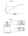
- the rate curve data 128 is illustrated in detail in Fig. 9A. It may include one or more rate curve data blocks 140 that may be used with one or both printing couples. Each data block 40 includes a rate curve ID 141 which uniquely identifies it. Each printing couple is associated with a particular rate curve data block by this rate curve ID number. As illustrated in Fig. 9B, a configuration database stored in the RAM 50 includes configuration records 142 for each printing couple. These configuration records 142 include a rate curve ID number which link each printing couple to one of the stored rate curve data blocks 140. These configuration records 142 can be altered by messages from the master work station 11 and, hence, the rate curve data block 140 associated with a particular printing couple can be altered at any time.
- Each rate curve data block 140 also stores a rate curve value 143 which indicates the current dampening water flow rate as calculated from the data in this rate curve data block 140 and the processed press speed 132.
- a third entry in the block 140 is the number of rate curve points which are stored in this data block 140 and the remainder of the data block 140 is comprised of the data which defines each of these points.
- Each point is defined by a press speed number 144 and a flow percent number 145. Anywhere from two to ten points may be stored which indicate the desired dampening water flow rates across a range of press speeds.
- the rate curve value 143 is calculated by linearly interpolating between the flow percent numbers 145 for the points which have press speed numbers 144 to each side of the processed press speed 131.
- each printing couple may have up to eight separately controllable nozzles 30 on its spraybar 26.
- the number is indicated in the configuration record 142 for each couple.
- the nozzle data block 135 in the control database 52 stores data on each controllable nozzle 30. More specifically, the status 150 of each nozzle is stored (idle/change requested/change in progress). Also, stored in this block 135 is the current pulse width value 151 which indicates the value actually being output to the PIC 70 or 72 (Fig. 5), the desired pulse width value 152 which indicates the pulse width which has been commanded, and the normalized pulse width value 153 which indicates the current value unmodified by any flood request or the like.
- the nozzle data block 135 is employed to control each nozzle 30 and to implement a change in the pulse width produced by each nozzle 30 in response to messages received over the serial link from the communications processor 30 (Fig. 4).
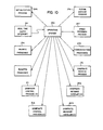
- the programs which direct the operation of the microprocessor 42 and, hence, control the operation of the drink processor 35 are stored in the ROM 44.
- these programs include a set of programs which carry out specific tasks or processes as well as a real time clock interrupt service routine and an operating system program.
- the operating system program is indicated by block 200 and it is a commercially available program for the model 6800 microprocessor. It is responsible for the orderly allocation of processor time to each of the other programs.
- the operating system 200 is a real-time, multi-processing operating system kernel commercially available from Software Components Group, Inc. under the trademark "pSOS-68K".
- the operating system 200 acts as a nucleus of supervisory software which performs services on demand, schedules the running of other programs, manages and allocates resources, and generally coordinates multiple, asynchronous real-time activities.
- a ready process is one which can be run. Since only one ready process can be running at a given time on the microprocessor 42, the others must wait their turn. A ready process is allowed to run when its priority is higher than all the other ready processes.
- a running process is one that is being executed even if it is momentarily interrupted by a real time clock interrupt routine or it makes calls to I/O service routines. A process becomes blocked as a result of a deliberate action on the part of the process itself which causes it to wait.
- a process is blocked if it requests a message from an empty message queue, requests memory which is not presently available, waits for an event which is presently not pending, or pauses for a specified time interval.
- a blocked process becomes ready when a blocking condition disappears or is removed.
- the ready process having the highest priority is allowed to run.
- the operating system 200 places it in a ready list which is stored in the RAM 50 at a location which reflects its priority relative to the other processes on the ready list.
- the operating system will normally run the process at the top of this ready list when it returns to the application programs.
- an initialization process 205 is ready to run and is executed first.
- the initialization process creates, or spawns, the other processes for the operating system 200 and it establishes the data structures described above.
- a number of diagnostic functions such as memory checks and hardware checks are performed, and the programmable interface timer (PIT) 60 and programmable interface controllers (PIC) 70 and 72 are configured to operate as described above.
- the various system processes are activated so that upon return to the operating system 200, it will begin to run the highest priority process which is in the ready state.
- NVRAM archive process 206 which is executed each time it is signaled by another process that a change has been made in data which is archived.
- This program transfers data in the control database 52 to a nonvolatile memory (not shown in the drawings) where it is available for use when restarting after loss of power. After transferring the data, the process 206 blocks itself and returns to the operating system 200.
- the real time clock interrupt routine 201 is executed every 25 milliseconds in response to an interrupt from a real time clock.
- the real time clock is formed by a counter in the DUART 55 (Fig. 5) which produces an interrupt request signal for the microprocessor 42 on a line 66 every 25 milliseconds.
- the microprocessor 42 is vectored to the interrupt service routine 201 which records the passage of one or more increments of time.
- the service routine 201 decrements the time other processes have remaining before being reawakened. If, as a result, the wait time for any blocked process is decremented to zero, that process is unblocked and placed in the ready state by the real time clock interrupt.
- any process in the system may block its own execution for a selected time interval and the interrupt service routine 201 will unblock it after that time interval has expired.
- a speed feedback process 207 is executed each time a real time clock interrupt is received and processed by the interrupt routine 201.
- this routine reads the switches on the control panel 53 every 100 milliseconds through the PIT 60.
- the instantaneous press speed value 131 is stored in the control database 52 and if the press speed has changed by t.5%, an event is signaled to a number of processes, including inkrate processes indicated collectively at block 210 and damprate control processes 211 and 212.
- the switch states are stored in the switch database 51, and if a change has occurred, an event is signaled to one of the damprate message handlers 202 or 203, or one of the inkrate processes 210.
- the speed feedback process 207 will be further described below with respect to Fig. 11.
- Figs. 4 and 10 communications through the serial channel 31 with the communications processor 30 is handled by send and receive processes which are indicated collectively by the block 215 entitled “communications processes”.
- the format of the messages is illustrated in Fig. 16, where the "source” field identifies the origin of the message.
- the receive process inputs message data which is received through the DUART 55. When a message has been received, it checks the "destination" field of the message to determine if it is directed to the inkrate, register or damprate control on this drink processor 35. If not, an error reply message is created and passed to the send process for transmission back to the processor 30 through the serial link 31. Proper messages are stored in the receive message buffer 49 and the message is posted to the appropriate inkrate receive process, register receive process or damprate receive process 216.
- the send process creates outgoing messages and transmits them through the DUART 55 and serial link 31 to the communications processor 30.
- Message data is read from the send message buffers 66 and assembled into a message which conforms to the serial link protocol.
- the send process suspends itself and remains suspended until another process places a message in the send message buffer 66 and signals the send processor of the event.
- the damprate receive process 216 handles all messages in the receive message buffer 49 which are intended for damprate control. It validates the message and then processes it in accordance with the data segment "function" field (Fig. 16). Messages which change the damprate control values are passed to the damprate message handler 202 which is then activated by the damprate receive process 216. On the other hand, when a dampening rate curve specification message providing new curve points is received, the damprate receive process 216 updates the rate curve data 128 in the control database 52 directly. When a rate curve mode change is received, the message is passed to the message handler 202.
- Read request messages which seek current pulse width value 151, rate curve data 128 or mode information 126 are handled directly by the damprate receive process 216.
- the requested information is read from the control database 52 and placed in the send message buffer 66.
- the process 216 then activates the communication process (send) 215.
- the damprate receive process 216 becomes blocked until a new message is placed in the receive message buffer for it.
- Each damprate message handler 202 and 203 coordinates the flow of data incoming from both the speed feedback process 207 and the damprate receive process 216 for one printing couple (side 10 or side 13). Each is responsible for directing the corresponding damprate control process 211 or 212 to carry out the indicated function or change. It is also responsible for obtaining responses back from the damprate control process 211 or 212 that a function has been executed or that a change has been completed, and for formulating a corresponding responsive message. Responsive messages which indicate that a function has been performed or that a change in operating conditions has been completed are placed in the send message buffer 66 and the communications process (send) 215 is activated. The operation of the damprate message handler 202 and 203 will be described in more detail below with respect to Fig. 12.
- the damprate control processes 211 and 212 determine the rate at which the spraybar nozzles 30 are to be turned on and off. There is a damprate control process for each printing couple in the unit 10. These processes 211 and 212 also separately control the duration of time that each spraybar nozzle 30 remains on so that the spray pattern can be precisely trimmed over the entire width of the plate cylinder 21. As will be described in more detail below, when in the automatic mode the damprate control process 211 or 212 calculates the dampening flow rate based on the current press speed and the stored rate curve data. This calculation is performed each time the speed feedback process 207 indicates that press speed has changed by setting the update flag 130 in the control database 52.
- the dampening flow rate is set by the unit trim value 127 stored in the control database 52.
- This value as well as others can be manually changed by sending change messages which are passed to the damprate control process 211 or 212 by its associated damprate message handler 203 or 202.
- the damprate control 211 or 212 signals this event to its message handler 203 or 202 which initiates a responsive message as described above.
- the damprate control process will be described in more detail below with reference to Fig. 13.
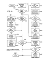
- the speed feedback process 207 is unblocked every 25 milliseconds by the real time clock interrupt 201.
- this process enters at 220 and decrements three 100 msec. timers as indicated by process block 221.
- One of these timers measures the interval between updates to press speed, another measures the interval between control panel scans, and the third measures 100 msec. "tics" on a variety of software timers. If none of these timers is decremented to zero, the process blocks itself for another 25 milliseconds and exits at 222 back to the operating system 200.
- the press speed is checked.
- the process branches at decision block 223 when the appropriate timer expires and the value of the timer 100 in the PIT 60 (Fig. 7) is read into the microprocessor 42 as indicated at process block 224.
- a new press speed sampling cycle is also initiating by writing a "1" " to the PCO output of the PIT 60.
- the instantaneous press speed is calculated at process block 225 by dividing the timer value into a constant which represents the distance moved by the press to produce sixteen incremental feedback pulses. The value is stored as the instantaneous press speed 131.
- a check is then made at decision block 226 to determine if the press speed has changed enough to warrant an update of the processed press speed.
- feedback process 207 reads the inputs from the control panel 53 as indicated at 231. This is accomplished be reading the 8-bit PB port on the PIT 60 (Fig. 5). The individual switch status bits are then masked out and compared at block 232 with the corresponding switch status bits in the switch database 51. If none of the switches have changed, the process branches at decision block 233. Otherwise, the changed switch status is updated in the switch database 51 at block 234 and the switch change event is signaled at block 235 to the proper damprate message handler process 202 or 203 or inkrate message handler 210.
- the feedback process 207 branches at decision block 236 to decrement the database timer values which are maintained for FLOOD, PURGE and WASH, as indicated at process block 237. If any such timer is reduced to zero, as determined at decision block 238, the appropriate message handler process is signaled at 239 that an event has occurred. For example, if the flood timer value 122 is decremented to zero, this event is signaled to the damprate message handler 202 or 203 for that printing couple. The functions performed by the speed feedback process 207 are then complete and the system exits at 222 back to the operating system 200.
- a source code listing of the speed feedback process 207 is provided in Appendix A.
- the damprate message handler 202 or 203 runs only when it is signaled by the speed feedback process 207 that a switch has changed state, or when it is signaled by the damprate receive process 216 that a change request, set request or flood request message has been received, or when the damprate control process 211 or 212 signals that a previous request has been completed.
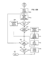
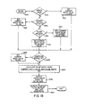
- Fig 12A when the damprate message handler 202 or 203 runs it examines the control status word 125 in the control database 52 as indicated by process block 250. If the control is in the process of making a change, the system branches as indicated to Fig. 12B. On the other hand, if the control is idle, then requested changes made to the message handler can be started. One type of change which can be requested is for a flood start from the local control panel 53 or a flood stop from the damprate control process 211 or 212. This is detected at decision block 251 which examines requests that are made to the damprate message handler. As indicated at decision block 252, the flood switch status 120 in the switch database 51 is then examined to determine if it is on.
- flood request flag 129 is set at block 253 to signal the damprate control process, and the flood examine flag 121 is reset at 254 so that the recognition of the state change in the flood switch is recognized only once.
- the flood timer 122 is then preset to a fixed value of 2 seconds at process block 255, and control status 125 is altered at block 256 to indicate "change in progress”.
- a "start" message is then passed to the communications process 215 at block 257 for sending to the master work station 11. The start message indicates that the flood operation has started.
- the flood timer value 122 is checked at decision block 260. As indicated above, this timer is decremented every 100 milliseconds by the speed feedback process 207 and when it reaches zero, the flood request flag 129 is reset at block 261 to signal the damprate control process that the flood operation is to terminate.
- the flood examine flag 121 is then set at block 262 so that a closure of the flood switch will be recognized as a new flood request, and the control status 125 is set at 263 to indicate "change in progress".
- Fig. 12A if the control status 125 is set to "change in progress" when the damprate message handler is run, the process branches at block 250 to Fig. 12B.
- a counter is then preset to the number of nozzles in the printing unit at block 265 and a loop is entered in which the nozzle status 150 (Fig. 9C) in each nozzle data record is examined.
- the nozzle status word 150 is read at block 266 and if it is set to "IDLE", the process branches at decision block 267 to decrement the nozzle counter at process block 268. On the other hand, if the nozzle status word 150 is set to "change complete" as determined at decision block 269, the process branches to decrement the nozzle counter at 270.
- a "STOP" message is then passed to the communications process 215 as indicated at block 271 and the nozzle status word 150 is set to "IDLE" at process block 272.
- the STOP message is conveyed through the serial channel 31 to the communications processor 30 to indicate that a change in nozzle pulse width has been completed.
- the nozzle counter will indicate the number of nozzles still in the "change in progress” state. If none are in this state as determined at decision block 274, the control status word 125 is changed to "IDLE" at process block 275 and the process exits at 276.
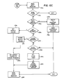
- the process branches to Fig. 12C to read at block 280 any messages which have been passed to it by the damprate receive process 216. If none are found, the process branches at decision block 281 and exits back to the operating system 200. Otherwise, the "function" field in the received message is analyzed to determine its type. If the received message contains rate curve mode set data, the process branches at decision block 282. The "mode" field in this message indicates if the control is to operate in the automatic or manual mode. As indicated at process block 283, if the indicated mode differs from that stored in the control mode word 136 of the control database 52, a mode switch is initiated. This includes changing the control mode word 136 to the new mode. A responsive message is then passed back to the communications process 215 at process block 284 to acknowledge that the message was received and acted upon.
- the process branches at decision block 285.
- the new pulse width values are extracted from the message at process block 286 and written into the desire width value word 152 of the associated nozzle data record.
- the nozzle status word 150 is then set to "change request” and the control status word 125 is set to "change in progress” at block 287.
- a START message is passed to the communications process 215 at block 288 to indicate that changes are being made to the nozzle pulse width in accordance with the SET message.
- a "CHANGE" message is received, as indicated at decision block 290, the increment of change for each nozzle 30 is extracted from the received message and is added to the nozzle's desired width value 152 in the control database 52. This is performed by a set of instructions represented by process block 291. The nozzle status 150 is then set to "change request” at block 287 and a "START" message is sent at process block 288 to indicate that the requested change is being made.
- a flood request message is received, as determined at decision block 292, the time value is extracted from the message and written to the flood timer value 122 in the switch database 51 at process block 293.
- the flood request flag 129 in the control database 52 is then set at process block 294 to initiate the flood operation and control status 125 is set to change requested.
- a "START" message is then sent at process block 288 to indicate that the flood operation has commenced.
- the damprate control processes 211 and 212 are run when an event is signaled by the speed feedback process 207 or the associated damprate message handler 202 or 203.
- the speed feedback process periodically updates the processed press speed 132 in the control database 52 and signals the damprate control process of this event.
- the damprate message handler signals the damprate control process of this event.
- the damprate control process operates the elements of the control system to carry out a change in either pulse rate or pulse width.
- this recalculation includes calculating a new flow rate percentage using the processed press speed 132 and rate curve data 128 as indicated at process block 301. This number indicates the percentage of maximum dampening water flow rate required at the current press speed.
- the unit trim value 127 is used a the % flow value in this calculation, whereas the value returned as a result of the calculation in process block 301 is used as the % flow value when in the automatic mode.
- the calculated current pulse rate value is converted to a value for the PIC timer 85 by the following expression:
- the newly calculated value is output to the timers 85 in the PICs 70 and 72 (Fig. 6). As indicated above, these timers are continuously decremented and each time they reach zero, a pulse is output which causes each nozzle 30 on the spraybars 26 to be turned on.
- the existence of a flood request is checked next at decision block 304. This is accomplished by examining the state of the flood request flag 129, the flood switch status 120, the flood switch examine flag 121, and the flood time value 122. The flood request flag 129 is either set or reset depending on the outcome of these examinations.
- a loop is then entered at process block 305 in which the status of each nozzle in the spraybar is examined. If the nozzle status 150 (Fig. 9C) indicates "change requested", then the process branches at decision block 306 to calculate a new pulse width value for the nozzle and output it to the PIC 70 or 72 as indicated at process block 307.
- the nozzle pulse width is set to the desired width value 152 plus a 25% flood increment if the flood request flag 129 is set.
- This pulse width number is saved as the current width value 151 and it is output to the PIC 70 or 72 along with a bit pattern that identifies the particular nozzle being set.
- the pulse width value is, therefore, loaded into the appropriate 8-bit counter 80 (Fig. 6) as described above.
- the current percentage flow value 137 is calculated at process block 309. This value represents the percentage of flow which would be required in manual mode to provide the same average flow as that currently being provided. It is a number which pressmen relate to and is commonly read out to the master control station 11 with a read message to provide an indication of dampening rate. And finally, the message handler is signaled at block 310 that an event has occurred which requires its attention and the process exits back to the operating system 200.
- the % flow value is calculated from the processed press speed 132 and the applicable rate curve data 128.
- a representative dampening rate curve is shown which is defined by six points P I -P G in a rate curve data block 140 (Fig. 9A). Each point is defined by a press speed and a flow percent value. Since a linear interpolating process is used in the preferred embodiment to calculate the % flow value for any given press speed, the curve is constructed with straight line segments between each point P I -P 6 .
- the two points on the curve which straddle the processed pressed speed (SPD) are first identified. This is accomplished by comparing the processed press speed 132 with the press speeds for each point in the rate curve data block. In the example, these are points P 3 and P 4 and the proper % flow value (%) is calculated by interpolating between these points as follows:
- a program listing for calculating the % flow value as described above is provided in Appendix B and the program listing for converting it and outputting it to the PIC 70 and 72 is provided in Appendix C.
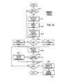
- a check is made to determine the mode of operation. If the dampening control system is in the manual mode, the system branches at decision block 326 and the current pulse width value is set to its midpoint, or 50% value, at process block 327. Otherwise, a check is made at decision block 328 to determine if the desired pulse width has been set to zero, and if it has, the current width value is also set to zero at process block 329. A check is next made at decision block 330 to determine if the flood request flag 129 has been set. If not, the current width value 151 is set to the desired width value 152 (Fig. 9C) at process block 331.
- the current width value is set to the desired value plus a 25% flood increment as indicated at process block 332. And finally, a check is made at decision block 333 to determine if the dampening system enable switch 124 (Fig. 8) off. If so, the current width value is set to zero as indicated at process block 334.
- the current width value is a percentage which is converted to an 8-bit binary pulse width count before being output. This is illustrated at process block 335 where the "MAX PULSE WIDTH" is a value of 100 in the preferred embodiment that produces a maximum pulse width of 50 milliseconds.
- the calculated pulse width count is then written to the PA port of the PIC 70 or 72 (Fig. 6) as indicated by process block 336.
- An 8-bit bit pattern in which a logical "1 " is directed to the counter 80 associated with the nozzle 30 is then written to the PB port of the PIC 70 or 72 and applied to the counters 80 as indicated by process block 337. As discussed above with reference to Fig.
- the 8-bit binary pulse width count at the PA port of the PIC 70 or 72 is stored in the counter 80 which receives the logic "1 from the PB port. As also explained above with respect to Fig. 13, this process is repeated for each nozzle 30 on the spraybar 26 and the counters 80 are thus separately preset with specific pulse width counts.
Landscapes
- Inking, Control Or Cleaning Of Printing Machines (AREA)
- Rotary Presses (AREA)
Applications Claiming Priority (2)
| Application Number | Priority Date | Filing Date | Title |
|---|---|---|---|
| US07/191,621 US4899653A (en) | 1988-05-09 | 1988-05-09 | Microprocessor-based press dampening control |
| US191621 | 1988-05-09 |
Publications (3)
| Publication Number | Publication Date |
|---|---|
| EP0341384A2 true EP0341384A2 (fr) | 1989-11-15 |
| EP0341384A3 EP0341384A3 (fr) | 1992-10-21 |
| EP0341384B1 EP0341384B1 (fr) | 1996-07-03 |
Family
ID=22706209
Family Applications (1)
| Application Number | Title | Priority Date | Filing Date |
|---|---|---|---|
| EP89103408A Expired - Lifetime EP0341384B1 (fr) | 1988-05-09 | 1989-02-27 | Dispositif de mouillage pour presse à imprimer commande par microprocesseur |
Country Status (6)
| Country | Link |
|---|---|
| US (1) | US4899653A (fr) |
| EP (1) | EP0341384B1 (fr) |
| JP (1) | JPH0259345A (fr) |
| AU (2) | AU614593B2 (fr) |
| CA (1) | CA1303899C (fr) |
| DE (1) | DE68926762T2 (fr) |
Cited By (3)
| Publication number | Priority date | Publication date | Assignee | Title |
|---|---|---|---|---|
| WO2000032397A1 (fr) * | 1998-12-02 | 2000-06-08 | Baldwin Jimek Ab | Procede et dispositif de commande d'une rampe de pulverisation dans une presse |
| EP1033245A1 (fr) * | 1999-03-01 | 2000-09-06 | Heidelberger Druckmaschinen Aktiengesellschaft | Dispositif de mouillage à haute fréquence effective de pulvérisation |
| CN1094832C (zh) * | 1997-10-22 | 2002-11-27 | 日本宝德温株式会社 | 润湿液供应方法和装置 |
Families Citing this family (15)
| Publication number | Priority date | Publication date | Assignee | Title |
|---|---|---|---|---|
| GB2182764B (en) * | 1985-11-12 | 1989-10-04 | British Gas Corp | Operation of a pulse firred burner |
| US5038681A (en) * | 1988-01-19 | 1991-08-13 | Jimek International Ab | Control method and apparatus for spray dampener |
| US5079738A (en) * | 1989-09-29 | 1992-01-07 | Rockwell International Corporation | Processor interconnect network for printing press system forming a star network |
| US5327833A (en) * | 1989-09-29 | 1994-07-12 | Rockwell International Corporation | Multiple ink zero calibration for printing press |
| US5460091A (en) * | 1990-10-30 | 1995-10-24 | Como Technologies, Inc. | Printing press ink supply system |
| US5412577A (en) * | 1992-10-28 | 1995-05-02 | Quad/Tech International | Color registration system for a printing press |
| US5592880A (en) * | 1993-12-30 | 1997-01-14 | Heidelberger Druckmaschinen | Method of supplying or feeding dampening solution |
| JP2644181B2 (ja) * | 1994-03-04 | 1997-08-25 | 株式会社東京機械製作所 | インキポンプの制御装置 |
| USD378188S (en) * | 1996-01-19 | 1997-02-25 | Yale Security Inc. | Front face of a key plug |
| US5791249A (en) * | 1997-03-27 | 1998-08-11 | Quad/Tech, Inc. | System and method for regulating dampening fluid in a printing press |
| DE19802920B4 (de) | 1998-01-27 | 2008-01-31 | Man Roland Druckmaschinen Ag | Verfahren und Vorrichtung zur Farbregelung in Druckmaschinen |
| DE10152466B4 (de) * | 2000-11-24 | 2015-12-17 | Heidelberger Druckmaschinen Ag | Feuchteregelung unter Berücksichtigung mehrerer den Druckprozess beeinflussender Größen |
| DE10208791C5 (de) * | 2001-03-12 | 2014-12-11 | Heidelberger Druckmaschinen Ag | Druckmaschinenantriebssystem |
| DE10258325B4 (de) * | 2002-10-25 | 2005-08-18 | Koenig & Bauer Ag | Verfahren zur Einstellung eines Sprühfeuchtwerks |
| SE543357C2 (en) * | 2018-06-29 | 2020-12-15 | Baldwin Jimek Ab | Service tracking system for spray bars and the like |
Family Cites Families (6)
| Publication number | Priority date | Publication date | Assignee | Title |
|---|---|---|---|---|
| US4064801A (en) * | 1975-08-12 | 1977-12-27 | Ryco Graphic Manufacturing, Inc. | Spray dampening system for offset printing |
| US4257005A (en) * | 1979-05-23 | 1981-03-17 | Hall David S | Fixed interval variable period pulse rate measuring method and system and tachometer system using same |
| US4506312A (en) * | 1982-03-09 | 1985-03-19 | Ford Aerospace & Communications Corporation | Apparatus for controlling the speed of a rotating body |
| US4469024A (en) * | 1982-10-18 | 1984-09-04 | Press Machinery Corporation | Fluid dispensing apparatus such as spray dampener for printing press and method of dispensing |
| US4797686A (en) * | 1985-05-01 | 1989-01-10 | Burlington Industries, Inc. | Fluid jet applicator for uniform applications by electrostatic droplet and pressure regulation control |
| US4649818A (en) * | 1985-07-22 | 1987-03-17 | Ryco Graphic Manufacturing, Inc. | Variable frequency pulsed spray dampening system |
-
1988
- 1988-05-09 US US07/191,621 patent/US4899653A/en not_active Expired - Lifetime
-
1989
- 1989-02-27 EP EP89103408A patent/EP0341384B1/fr not_active Expired - Lifetime
- 1989-02-27 DE DE68926762T patent/DE68926762T2/de not_active Expired - Fee Related
- 1989-03-02 CA CA000592609A patent/CA1303899C/fr not_active Expired - Lifetime
- 1989-04-03 AU AU32400/89A patent/AU614593B2/en not_active Ceased
- 1989-05-02 JP JP1113578A patent/JPH0259345A/ja active Pending
-
1991
- 1991-06-26 AU AU79326/91A patent/AU641774B2/en not_active Ceased
Cited By (5)
| Publication number | Priority date | Publication date | Assignee | Title |
|---|---|---|---|---|
| CN1094832C (zh) * | 1997-10-22 | 2002-11-27 | 日本宝德温株式会社 | 润湿液供应方法和装置 |
| WO2000032397A1 (fr) * | 1998-12-02 | 2000-06-08 | Baldwin Jimek Ab | Procede et dispositif de commande d'une rampe de pulverisation dans une presse |
| AU751026B2 (en) * | 1998-12-02 | 2002-08-08 | Baldwin Jimek Ab | A method and device at a spraying ramp for a printing press |
| EP1033245A1 (fr) * | 1999-03-01 | 2000-09-06 | Heidelberger Druckmaschinen Aktiengesellschaft | Dispositif de mouillage à haute fréquence effective de pulvérisation |
| US6327974B1 (en) | 1999-03-01 | 2001-12-11 | Heidelberger Druckmaschinen Ag | Spray dampening device having high effective spray frequency and method of using |
Also Published As
| Publication number | Publication date |
|---|---|
| AU641774B2 (en) | 1993-09-30 |
| JPH0259345A (ja) | 1990-02-28 |
| DE68926762D1 (de) | 1996-08-08 |
| EP0341384B1 (fr) | 1996-07-03 |
| AU3240089A (en) | 1989-11-09 |
| CA1303899C (fr) | 1992-06-23 |
| US4899653A (en) | 1990-02-13 |
| AU614593B2 (en) | 1991-09-05 |
| AU7932691A (en) | 1991-09-12 |
| EP0341384A3 (fr) | 1992-10-21 |
| DE68926762T2 (de) | 1996-11-14 |
Similar Documents
| Publication | Publication Date | Title |
|---|---|---|
| US4899653A (en) | Microprocessor-based press dampening control | |
| US5027706A (en) | Press inking system | |
| CA2022058C (fr) | Reseau d'interconnexion de processeurs pour presse a imprimer | |
| US5392706A (en) | Pad transfer printing method | |
| WO2002025414A3 (fr) | Procede et appareil de gestion d'horloges en fonction des conditions ambiantes | |
| US5148747A (en) | Process for setting a production run ink zone profile | |
| US5479352A (en) | System for accurately positioning operations on conveyed products | |
| US5327833A (en) | Multiple ink zero calibration for printing press | |
| EP0911160B1 (fr) | Procédé et appareil d'alimentation en eau de mouillage | |
| EP0422365B1 (fr) | Courbes multiples d'encre et d'eau pour des presses | |
| US5010812A (en) | Electronic device for controlling a printing machine | |
| JPH05220936A (ja) | オフセット印刷機の印刷稼動時インキ輪郭を設定調整する方法 | |
| EP0419812B1 (fr) | Etalonnage multiple d'encrage au zéro pour machines d'impression | |
| CA2209974A1 (fr) | Dispositif pour etablir rapidement un etat de production pour une presse rotative a bobines | |
| US6213019B1 (en) | Method and apparatus for ink feed control | |
| US5887521A (en) | Dampening water supply device | |
| JP2513476B2 (ja) | インキ量制御装置の修正値表示方法 | |
| CH649037A5 (de) | Farbdosiereinrichtung fuer druckmaschinen. | |
| US4897793A (en) | Configuration for a franking machine | |
| SU1317286A1 (ru) | Дозатор сыпучих материалов | |
| US20020030707A1 (en) | Modular dampening system spray bar having individual, localized control spray nozzles | |
| JPS63112150A (ja) | 裏移り防止用スプレ−の制御方法及び装置 | |
| USRE35444E (en) | Ink washing device for a printing machine | |
| EP0300389A2 (fr) | Procédé et dispositif pour alimenter en encre des presses à imprimer | |
| DE59506166D1 (de) | Steuerung für die Drucktuch-Wascheinrichtung einer Offset-Rotationsdruckmaschine mit mehreren Druckwerken |
Legal Events
| Date | Code | Title | Description |
|---|---|---|---|
| PUAI | Public reference made under article 153(3) epc to a published international application that has entered the european phase |
Free format text: ORIGINAL CODE: 0009012 |
|
| AK | Designated contracting states |
Kind code of ref document: A2 Designated state(s): CH DE FR GB LI SE |
|
| PUAL | Search report despatched |
Free format text: ORIGINAL CODE: 0009013 |
|
| AK | Designated contracting states |
Kind code of ref document: A3 Designated state(s): CH DE FR GB LI SE |
|
| 17P | Request for examination filed |
Effective date: 19930406 |
|
| 17Q | First examination report despatched |
Effective date: 19950214 |
|
| GRAH | Despatch of communication of intention to grant a patent |
Free format text: ORIGINAL CODE: EPIDOS IGRA |
|
| GRAA | (expected) grant |
Free format text: ORIGINAL CODE: 0009210 |
|
| AK | Designated contracting states |
Kind code of ref document: B1 Designated state(s): CH DE FR GB LI SE |
|
| REG | Reference to a national code |
Ref country code: CH Ref legal event code: NV Representative=s name: TROESCH SCHEIDEGGER WERNER AG |
|
| REF | Corresponds to: |
Ref document number: 68926762 Country of ref document: DE Date of ref document: 19960808 |
|
| ET | Fr: translation filed | ||
| PLBE | No opposition filed within time limit |
Free format text: ORIGINAL CODE: 0009261 |
|
| STAA | Information on the status of an ep patent application or granted ep patent |
Free format text: STATUS: NO OPPOSITION FILED WITHIN TIME LIMIT |
|
| 26N | No opposition filed | ||
| REG | Reference to a national code |
Ref country code: CH Ref legal event code: PUE Owner name: ROCKWELL INTERNATIONAL CORPORATION TRANSFER- GOSS |
|
| REG | Reference to a national code |
Ref country code: FR Ref legal event code: TP |
|
| REG | Reference to a national code |
Ref country code: GB Ref legal event code: 732E |
|
| REG | Reference to a national code |
Ref country code: GB Ref legal event code: IF02 |
|
| PGFP | Annual fee paid to national office [announced via postgrant information from national office to epo] |
Ref country code: FR Payment date: 20060217 Year of fee payment: 18 |
|
| PGFP | Annual fee paid to national office [announced via postgrant information from national office to epo] |
Ref country code: GB Payment date: 20060223 Year of fee payment: 18 |
|
| PGFP | Annual fee paid to national office [announced via postgrant information from national office to epo] |
Ref country code: CH Payment date: 20060227 Year of fee payment: 18 |
|
| PGFP | Annual fee paid to national office [announced via postgrant information from national office to epo] |
Ref country code: DE Payment date: 20060331 Year of fee payment: 18 |
|
| PG25 | Lapsed in a contracting state [announced via postgrant information from national office to epo] |
Ref country code: SE Free format text: LAPSE BECAUSE OF NON-PAYMENT OF DUE FEES Effective date: 20070228 Ref country code: LI Free format text: LAPSE BECAUSE OF NON-PAYMENT OF DUE FEES Effective date: 20070228 Ref country code: CH Free format text: LAPSE BECAUSE OF NON-PAYMENT OF DUE FEES Effective date: 20070228 |
|
| REG | Reference to a national code |
Ref country code: CH Ref legal event code: PL |
|
| EUG | Se: european patent has lapsed | ||
| GBPC | Gb: european patent ceased through non-payment of renewal fee |
Effective date: 20070227 |
|
| REG | Reference to a national code |
Ref country code: FR Ref legal event code: ST Effective date: 20071030 |
|
| PG25 | Lapsed in a contracting state [announced via postgrant information from national office to epo] |
Ref country code: DE Free format text: LAPSE BECAUSE OF NON-PAYMENT OF DUE FEES Effective date: 20070901 |
|
| PGFP | Annual fee paid to national office [announced via postgrant information from national office to epo] |
Ref country code: SE Payment date: 20060227 Year of fee payment: 18 |
|
| PG25 | Lapsed in a contracting state [announced via postgrant information from national office to epo] |
Ref country code: FR Free format text: LAPSE BECAUSE OF NON-PAYMENT OF DUE FEES Effective date: 20070228 Ref country code: GB Free format text: LAPSE BECAUSE OF NON-PAYMENT OF DUE FEES Effective date: 20070227 |