EP0341142B1 - Beobachtungsvorrichtung durch Abtastung eines Raumkörpers und Messung der Winkelgeschwindigkeit eines Raumfahrzeuges, Beobachtungssystem für seine Anwendung und Raumfahrzeug mit diesem System - Google Patents
Beobachtungsvorrichtung durch Abtastung eines Raumkörpers und Messung der Winkelgeschwindigkeit eines Raumfahrzeuges, Beobachtungssystem für seine Anwendung und Raumfahrzeug mit diesem System Download PDFInfo
- Publication number
- EP0341142B1 EP0341142B1 EP89401210A EP89401210A EP0341142B1 EP 0341142 B1 EP0341142 B1 EP 0341142B1 EP 89401210 A EP89401210 A EP 89401210A EP 89401210 A EP89401210 A EP 89401210A EP 0341142 B1 EP0341142 B1 EP 0341142B1
- Authority
- EP
- European Patent Office
- Prior art keywords
- scanning
- axis
- celestial body
- optical
- space vehicle
- Prior art date
- Legal status (The legal status is an assumption and is not a legal conclusion. Google has not performed a legal analysis and makes no representation as to the accuracy of the status listed.)
- Expired - Lifetime
Links
Images


Classifications
-
- G—PHYSICS
- G01—MEASURING; TESTING
- G01S—RADIO DIRECTION-FINDING; RADIO NAVIGATION; DETERMINING DISTANCE OR VELOCITY BY USE OF RADIO WAVES; LOCATING OR PRESENCE-DETECTING BY USE OF THE REFLECTION OR RERADIATION OF RADIO WAVES; ANALOGOUS ARRANGEMENTS USING OTHER WAVES
- G01S3/00—Direction-finders for determining the direction from which infrasonic, sonic, ultrasonic or electromagnetic waves, or particle emission, not having a directional significance, are being received
- G01S3/78—Direction-finders for determining the direction from which infrasonic, sonic, ultrasonic or electromagnetic waves, or particle emission, not having a directional significance, are being received using electromagnetic waves other than radio waves
- G01S3/782—Systems for determining direction or deviation from predetermined direction
- G01S3/785—Systems for determining direction or deviation from predetermined direction using adjustment of orientation of directivity characteristics of a detector or detector system to give a desired condition of signal derived from that detector or detector system
- G01S3/786—Systems for determining direction or deviation from predetermined direction using adjustment of orientation of directivity characteristics of a detector or detector system to give a desired condition of signal derived from that detector or detector system the desired condition being maintained automatically
- G01S3/7868—Systems for determining direction or deviation from predetermined direction using adjustment of orientation of directivity characteristics of a detector or detector system to give a desired condition of signal derived from that detector or detector system the desired condition being maintained automatically using horizon sensors
-
- B—PERFORMING OPERATIONS; TRANSPORTING
- B64—AIRCRAFT; AVIATION; COSMONAUTICS
- B64G—COSMONAUTICS; VEHICLES OR EQUIPMENT THEREFOR
- B64G1/00—Cosmonautic vehicles
- B64G1/22—Parts of, or equipment specially adapted for fitting in or to, cosmonautic vehicles
- B64G1/24—Guiding or controlling apparatus, e.g. for attitude control
- B64G1/36—Guiding or controlling apparatus, e.g. for attitude control using sensors, e.g. sun-sensors, horizon sensors
- B64G1/365—Guiding or controlling apparatus, e.g. for attitude control using sensors, e.g. sun-sensors, horizon sensors using horizon or Earth sensors
-
- G—PHYSICS
- G01—MEASURING; TESTING
- G01P—MEASURING LINEAR OR ANGULAR SPEED, ACCELERATION, DECELERATION, OR SHOCK; INDICATING PRESENCE, ABSENCE, OR DIRECTION, OF MOVEMENT
- G01P3/00—Measuring linear or angular speed; Measuring differences of linear or angular speeds
- G01P3/64—Devices characterised by the determination of the time taken to traverse a fixed distance
- G01P3/68—Devices characterised by the determination of the time taken to traverse a fixed distance using optical means, i.e. using infrared, visible, or ultraviolet light
-
- B—PERFORMING OPERATIONS; TRANSPORTING
- B64—AIRCRAFT; AVIATION; COSMONAUTICS
- B64G—COSMONAUTICS; VEHICLES OR EQUIPMENT THEREFOR
- B64G1/00—Cosmonautic vehicles
- B64G1/22—Parts of, or equipment specially adapted for fitting in or to, cosmonautic vehicles
- B64G1/66—Arrangements or adaptations of apparatus or instruments, not otherwise provided for
Landscapes
- Engineering & Computer Science (AREA)
- Remote Sensing (AREA)
- Physics & Mathematics (AREA)
- General Physics & Mathematics (AREA)
- Radar, Positioning & Navigation (AREA)
- General Life Sciences & Earth Sciences (AREA)
- Life Sciences & Earth Sciences (AREA)
- Environmental & Geological Engineering (AREA)
- Electromagnetism (AREA)
- Geochemistry & Mineralogy (AREA)
- Geology (AREA)
- Chemical & Material Sciences (AREA)
- Combustion & Propulsion (AREA)
- Aviation & Aerospace Engineering (AREA)
- Navigation (AREA)
- Gyroscopes (AREA)
Claims (10)
- Verfahren zur Beobachtung eines Himmelskörpers (T) durch Abtastung von einem Raumfahrzeug (S) aus, das ein System zur Beobachtung durch Abtastung gemäß einer Abtastachse (X-X) mit einer optischen Vorrichtung (12) umfaßt, dadurch gekennzeichnet, daß gleichzeitig bei jeder Abtastung zwei Signale gebildet werden, die der Abtastung von zwei parallelen Bodenbändern entsprechen, die von der optischen Vorrichtung unter einem Winkel (α) gesehen werden, der gleich einem ganzzahligen Vielfachen und wenigstens gleich dem Einfachen des Winkels (β) ist, unter welchem diese optische Vorrichtung den Abstand (e) zwischen zwei benachbarten, den Himmelskörper (T) schneidenden Abtastlinien (Ln, Ln+1) sieht, so daß ein und dasselbe Bodenband (BT) bei zwei verschiedenen Abtastungen aufgezeichnet wird, daß man unter Berücksichtigung der Abtastrichtung in jedem der der Abtastung ein und desselben Bodenbandes (BT) entsprechenden Signale einen charakteristischen Übergang (A1, B1) erfaßt (17), der ein und denselben charakteristischen Punkt dieses Bodenbandes darstellt, daß man die relative Stellung dieser Übergänge in diesen Signalen ermittelt (18) und aus einem ggf. bestehenden Abstand zwischen diesen relativen Stellungen eine ggf. vorhandene Winkelgeschwindigkeit (ω̇) des Raumfahrzeugs unter Berücksichtigung des zeitlichen Abstands zwischen den Zeitpunkten des Auftretens jedes der Übergänge in den Signalen bestimmt (19).
- Beobachtungsverfahren nach Anspruch 1, dadurch gekennzeichnet, daß man diesen Winkelabstand oder diese Winkelgeschwindigkeit zur Steuerung der Fluglage des Raumfahrzeugs um die Abtastachse herum durch Aufhebung der festgestellten Abweichung verwendet.
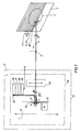
- System (10) zur Beobachtung eines Himmelskörpers (T) für ein Raumfahrzeug (S) mit einer optischen Abtastvorrichtung (12), die den Himmelkörper gemäß einer Abtastachse (X-X) Zeile für Zeile abtasten kann, einer Einheit (13) zur Aufnahme von Bildern des Himmelskörpers (T) in der Brennebene (P) dieser optischen Vorrichtung und in deren optischen Achse und einem mit dieser Erfassungseinheit verbundenen System (14) zur Herstellung und Verarbeitung von Bildern, gekennzeichnet durch ein erstes (1; 1, 1') und ein zweites (2; 2, 2') Erfassungselement mit gleichen spektralen Charakteristiken, die in der Brennebene angeordnet und parallel zur Abtastachse (X-X) in einem Abstand (d) gegeneinander versetzt sind, der von der optischen Vorrichtung (12) unter einem Winkel (α) gesehen wird, der gleich einem ganzzahligen Vielfachen und wenigstens gleich dem Einfachen des Winkels (β) ist, unter welchem diese optische Vorrichtung den Abstand (e) zwischen zwei benachbarten den Himmelskörper (T) schneidenden Abtastlinien (Ln, Ln+1) sieht, sowie eine mit jeden dieser Erfassungselemente verbundene Vorrichtung (15) zur Winkelgeschwindigkeitsverarbeitung und -messung, die umfaßt:- eine Schaltung (16), die nacheinander über das eine und dann über das andere Erfassungselement Signale (A, B) aufnimmt, die ein und dasselbe auf dem Himmelskörper abgetastete Bodenband darstellen und in die gleiche Durchlaufrichtung auf diesem Bodenband gebracht werden,- eine Schaltung (17) zur Erfassung eines charakteristischen Übergangs (A1, B1) in jedem dieser Signale (A, B), der ein und denselben charakteristischen Punkt des Bodenbandes darstellt,- eine Schaltung (18) zur Ermittlung der relativen Stellung jedes Übergangs bezüglich des ihn enthaltenden Signals, und- eine Rechenschaltung (19), die aus einem ggf. bestehenden Abstand zwischen diesen relativen Stellungen eine ggf. vorhandene Winkelgeschwindigkeit des Raumfahrzeugs um eine zur Abtastachse parallele Achse unter Berücksichtigung des zeitlichen Abstands zwischen den Zeitpunkten, an denen die charakeristischen Übergänge festgestellt wurden, bestimmen kann.
- System nach Anspruch 3, dadurch gekennzeichnet, daß das erste Erfassungselement (1) in der optischen Achse (Z-Z) des optischen Abtastsystems angeordnet ist.
- System nach Anspruch 3 oder 4, dadurch gekennzeichnet, daß das erste Erfassungselement einen Teil der Einheit (13) zur Aufnahme von Bildern des Himmelskörpers (T) bildet.
- System nach einem der Ansprüche 3 bis 5, dadurch gekennzeichnet, daß jedes der Erfassungselemente in zwei Unterelemente (1, 2; 1', 2') geteilt ist, die parallel zur Abtastachse gegeneinander versetzt sind, wobei jedes Unterelement insgesamt in der Brennebene bezüglich der optischen Achse parallel zur Abtastachse versetzt ist.
- System nach einem der Ansprüche 3 bis 6, dadurch gekennzeichnet, daß die Winkel (α, β), unter denen das optische System einerseits den Abstand zwischen den Erfassungselementen (1, 2) und andererseits den Abstand zwischen zwei benachbarten Abtastzeilen sieht, gleich sind.
- System nach einem der Ansprüche 3 bis 6, dadurch gekennzeichnet, daß der Winkel (α), unter dem das optische System den Abstand zwischen den Erfassungselementen sieht, ein geradzahliges Vielfaches des Winkels (β) ist, unter welchem diese Vorrichtung den Abstand zwischen zwei benachbarten Abtastzeilen sieht, wobei der Abstand zwischen den charakteristischen Übergängen definiert ist durch den Abstand zwischen dem die charakteristischen Übergänge trennenden Zeitintervall und demselben geradzahligen Vielfachen der Abtastdauer jeder Zeile.
- System nach einem der Ansprüche 3 bis 8, dadurch gekennzeichnet, daß die Erfassungselemente (1, 2) für Infrarotstrahlen empfindlich sind.
- Raumfahrzeug, das ein Beobachtungssystem nach einem der Ansprüche 3 bis 9 sowie Winkelgeschwindigkeitsdetektoren (11) umfaßt, die zur Abtastachse senkrechten Drehachsen zugeordnet sind.
Applications Claiming Priority (2)
| Application Number | Priority Date | Filing Date | Title |
|---|---|---|---|
| FR8805708 | 1988-04-28 | ||
| FR8805708A FR2630705B1 (fr) | 1988-04-28 | 1988-04-28 | Procede d'observation par balayage d'un corps celeste et de mesure d'une vitesse angulaire d'un vehicule spatial, systeme d'observation pour sa mise en oeuvre, et vehicule spatial le comportant |
Publications (3)
| Publication Number | Publication Date |
|---|---|
| EP0341142A2 EP0341142A2 (de) | 1989-11-08 |
| EP0341142A3 EP0341142A3 (en) | 1989-11-15 |
| EP0341142B1 true EP0341142B1 (de) | 1993-07-07 |
Family
ID=9365796
Family Applications (1)
| Application Number | Title | Priority Date | Filing Date |
|---|---|---|---|
| EP89401210A Expired - Lifetime EP0341142B1 (de) | 1988-04-28 | 1989-04-27 | Beobachtungsvorrichtung durch Abtastung eines Raumkörpers und Messung der Winkelgeschwindigkeit eines Raumfahrzeuges, Beobachtungssystem für seine Anwendung und Raumfahrzeug mit diesem System |
Country Status (7)
| Country | Link |
|---|---|
| US (1) | US5062051A (de) |
| EP (1) | EP0341142B1 (de) |
| JP (1) | JP2740920B2 (de) |
| CA (1) | CA1326529C (de) |
| DE (1) | DE68907440T2 (de) |
| ES (1) | ES2043056T3 (de) |
| FR (1) | FR2630705B1 (de) |
Families Citing this family (13)
| Publication number | Priority date | Publication date | Assignee | Title |
|---|---|---|---|---|
| FR2653918B1 (fr) * | 1989-10-31 | 1992-02-14 | Europ Agence Spatiale | Procede de rectification en temps reel des images des satellites meteorologiques geostationnaires. |
| US5257760A (en) * | 1992-06-24 | 1993-11-02 | Edo Corporation, Barnes Engineering Division | Scanning earth sensor using the sun's position for determining yaw |
| US5546309A (en) * | 1993-10-20 | 1996-08-13 | The Charles Stark Draper Laboratory, Inc. | Apparatus and method for autonomous satellite attitude sensing |
| US6732977B1 (en) | 2002-02-11 | 2004-05-11 | Lockheed Martin Corporation | System for on-orbit correction of spacecraft payload pointing errors |
| US6695263B1 (en) * | 2002-02-12 | 2004-02-24 | Lockheed Martin Corporation | System for geosynchronous spacecraft rapid earth reacquisition |
| US7051980B2 (en) * | 2002-02-26 | 2006-05-30 | Lockheed Martin Corporation | Efficient orbit sparing system for space vehicle constellations |
| US6702234B1 (en) | 2002-03-29 | 2004-03-09 | Lockheed Martin Corporation | Fault tolerant attitude control system for zero momentum spacecraft |
| US7835826B1 (en) | 2005-12-13 | 2010-11-16 | Lockheed Martin Corporation | Attitude determination system for yaw-steering spacecraft |
| JP4820976B2 (ja) * | 2006-10-06 | 2011-11-24 | 株式会社指月電機製作所 | トランスコアの固定構造 |
| US8767072B1 (en) * | 2010-03-26 | 2014-07-01 | Lockheed Martin Corporation | Geoposition determination by starlight refraction measurement |
| CN106225807A (zh) * | 2016-07-27 | 2016-12-14 | 中国科学院长春光学精密机械与物理研究所 | 视频卫星对地面区域目标进行凝视成像的仿真方法及系统 |
| US10612901B2 (en) * | 2018-03-23 | 2020-04-07 | Simmonds Precision Products, Inc. | Real-time compensation of inertial gyroscopes |
| CN111897357B (zh) * | 2020-08-13 | 2023-10-20 | 上海航天控制技术研究所 | 一种卫星对地扫描的姿态跟踪控制方法 |
Family Cites Families (26)
| Publication number | Priority date | Publication date | Assignee | Title |
|---|---|---|---|---|
| CA633497A (en) * | 1961-12-26 | Collins Radio Company | Satellite apparent position computer | |
| US2998529A (en) * | 1958-06-19 | 1961-08-29 | Kollsman Instr Corp | Automatic astrocompass |
| US3012728A (en) * | 1958-07-23 | 1961-12-12 | Collins Radio Co | Satellite apparent position computer |
| US3216674A (en) * | 1959-06-08 | 1965-11-09 | Walter G Finch | Proportional navigation system for a spinning body in free space |
| US3310982A (en) * | 1961-08-31 | 1967-03-28 | United Aircraft Corp | Navigation system with vehicle motion signals modified by drift angle signals |
| US3576999A (en) * | 1965-01-16 | 1971-05-04 | Bendix Corp | Method and apparatus for determining the orientation of an object relative to an elliptic object |
| US3535521A (en) * | 1966-02-28 | 1970-10-20 | Itt | Satellite attitude control utilizing a plurality of infrared sensors |
| US3769710A (en) * | 1969-04-01 | 1973-11-06 | R Reister | Electronic celestial navigation means |
| JPS4829075B1 (de) | 1969-07-25 | 1973-09-06 | ||
| FR2246843B1 (de) * | 1973-10-04 | 1976-05-14 | Sodern | |
| US4328421A (en) * | 1980-02-25 | 1982-05-04 | Barnes Engineering Company | Horizon sensor |
| US4617634A (en) * | 1983-06-28 | 1986-10-14 | Mitsubishi Denki Kabushiki Kaisha | Artificial satellite attitude control system |
| JPS6025900A (ja) * | 1983-07-25 | 1985-02-08 | 株式会社日立製作所 | スタ−センサによる姿勢決定システム |
| DE3330861A1 (de) * | 1983-08-26 | 1985-03-14 | Messerschmitt-Bölkow-Blohm GmbH, 8012 Ottobrunn | Vorrichtung zur feststellung von lageaenderungen eines raumflugkoerpers |
| JPS60104499A (ja) * | 1983-11-11 | 1985-06-08 | 株式会社日立製作所 | 姿勢決定方式 |
| DE3422007C2 (de) * | 1984-06-14 | 1986-10-02 | Messerschmitt-Bölkow-Blohm GmbH, 8012 Ottobrunn | Anordnung für einen Erdhorizontsensor eines in einem Orbit befindlichen Erdsatelliten |
| US4628206A (en) | 1984-08-27 | 1986-12-09 | Barnes Engineering Company | Visible-UV horizon sensor |
| US4837699A (en) * | 1985-07-18 | 1989-06-06 | Hughes Aircraft Company | Method for controlling the spin axis attitude of a spinning spacecraft |
| US4801202A (en) * | 1985-12-20 | 1989-01-31 | Itt Aerospace Optical | Method and apparatus for radiometer star sensing |
| SE461835B (sv) * | 1986-02-13 | 1990-04-02 | Sparring Elfa Ab | Hjulfaeste foer monterbara moebeldelar |
| US4688092A (en) * | 1986-05-06 | 1987-08-18 | Ford Aerospace & Communications Corporation | Satellite camera image navigation |
| US4827422A (en) * | 1986-12-04 | 1989-05-02 | Barnes Engineering Company | Fan scan horizon sensor for a spin stabilized satellite |
| US4912475A (en) * | 1987-03-20 | 1990-03-27 | Massachusetts Institute Of Technology | Techniques for determining orbital data |
| FR2615477B1 (fr) * | 1987-05-22 | 1989-08-18 | Centre Nat Etd Spatiales | Dispositif et procede de pointage d'une sonde spatiale vers un corps celeste |
| US4944587A (en) * | 1988-03-17 | 1990-07-31 | Kabushiki Kaisha Toshiba | Star sensor |
| GB8809247D0 (en) * | 1988-04-20 | 1988-05-25 | British Aerospace | Attitude recovery for spacecraft |
-
1988
- 1988-04-28 FR FR8805708A patent/FR2630705B1/fr not_active Expired - Fee Related
-
1989
- 1989-04-25 CA CA000597737A patent/CA1326529C/en not_active Expired - Fee Related
- 1989-04-27 DE DE89401210T patent/DE68907440T2/de not_active Expired - Fee Related
- 1989-04-27 EP EP89401210A patent/EP0341142B1/de not_active Expired - Lifetime
- 1989-04-27 ES ES89401210T patent/ES2043056T3/es not_active Expired - Lifetime
- 1989-04-28 JP JP1111895A patent/JP2740920B2/ja not_active Expired - Lifetime
- 1989-05-01 US US07/345,592 patent/US5062051A/en not_active Expired - Fee Related
Also Published As
| Publication number | Publication date |
|---|---|
| US5062051A (en) | 1991-10-29 |
| FR2630705B1 (fr) | 1990-08-24 |
| ES2043056T3 (es) | 1993-12-16 |
| CA1326529C (en) | 1994-01-25 |
| JPH0249111A (ja) | 1990-02-19 |
| EP0341142A3 (en) | 1989-11-15 |
| JP2740920B2 (ja) | 1998-04-15 |
| DE68907440T2 (de) | 1993-11-04 |
| EP0341142A2 (de) | 1989-11-08 |
| DE68907440D1 (de) | 1993-08-12 |
| FR2630705A1 (fr) | 1989-11-03 |
Similar Documents
| Publication | Publication Date | Title |
|---|---|---|
| EP0341142A2 (de) | Beobachtungsvorrichtung durch Abtastung eines Raumkörpers und Messung der Winkelgeschwindigkeit eines Raumfahrzeuges, Beobachtungssystem für seine Anwendung und Raumfahrzeug mit diesem System | |
| FR2638544A1 (fr) | Systeme pour determiner la position spatiale d'un objet en mouvement, applique notamment a l'atterrissage des avions | |
| EP0241374B1 (de) | Optronische Abweichungsvorrichtung zur räumlichen und spektralen Erkennung von infraroten Lichtquellen | |
| EP0790505A1 (de) | Schlitz-Sonnensensor | |
| EP0405678B1 (de) | Erd-Horizontsensor mit verbesserter Genauigkeit | |
| FR2602057A1 (fr) | Procede et dispositif de mesure de distance par voie optique | |
| EP0499319B1 (de) | Verfahren zur Messung der genauen Position des Energiezentrums eines Bildflecks eines lichtstrahlenden Gegenstandes auf einem Photosensor | |
| FR2597985A1 (fr) | Procede et dispositif de prise de vues d'un objet ligne par ligne | |
| WO1991006919A1 (fr) | Procede de rectification en temps reel d'images de satellites meteorologiques geostationnaires | |
| FR3112849A1 (fr) | Procédé et système pour détecter une ou plusieurs cibles dans l’espace à partir d’images prises depuis un engin spatial tel qu’un satellite d’inspection visuelle, et satellite équipé d’un tel système | |
| WO2023089275A1 (fr) | Procédé d'acquisition d'images d'un objet spatial en orbite terrestre par un engin spatial en orbite terrestre | |
| EP0064439B1 (de) | Kartographischer Anweiser mit photographischer Registrierung | |
| EP0697786B1 (de) | Sensoreinrichtung zur Erderfassung für einen Satelliten oder Ähnliches mit einer pyroelektrischen Detektormatrix | |
| FR2981149A1 (fr) | Aeronef comprenant un senseur optique diurne et nocturne, et procede de mesure d'attitude associe | |
| FR2533883A1 (fr) | Senseur d'horizon terrestre utilisant des photodetecteurs a transfert de charges | |
| EP0608945B1 (de) | Sterndetektor mit ladungsgekoppelter Matrix, Verfahren zur Detektion und Anwendung zur Neueinstellung eines Raumfahrzeuges | |
| EP3671280B1 (de) | Hochpräzises datierungssystem der passage eines objekts, insbesondere eines satelliten | |
| FR2497943A1 (fr) | Perfectionnements aux procedes et dispositifs de navigation par relocalisation d'un mobile sur une carte | |
| FR2612647A1 (fr) | Dispositif de modulation pour un dispositif detecteur de rayonnement captant un champ d'image | |
| EP0445038B1 (de) | Bildabtastungsvorrichtung, bestehend aus einer Matrix statischer Ladungssensoren | |
| FR3082614A1 (fr) | Dispositif de positionnement astronomique par observation diurne ou nocturne d'un astre | |
| FR2598814A1 (fr) | Dispositif de localisation optoelectronique. | |
| EP0516543B1 (de) | Laufende, optoelektronische Bildaufnahmevorrichtung | |
| FR2551201A1 (fr) | Dispositif pour determiner les variations d'orientation d'un engin spatial | |
| FR2611266A1 (fr) | Dispositif et procede de localisation de vues au sol prises d'un satellite |
Legal Events
| Date | Code | Title | Description |
|---|---|---|---|
| PUAI | Public reference made under article 153(3) epc to a published international application that has entered the european phase |
Free format text: ORIGINAL CODE: 0009012 |
|
| PUAL | Search report despatched |
Free format text: ORIGINAL CODE: 0009013 |
|
| AK | Designated contracting states |
Kind code of ref document: A2 Designated state(s): DE ES GB IT NL SE |
|
| AK | Designated contracting states |
Kind code of ref document: A3 Designated state(s): DE ES GB IT NL SE |
|
| 17P | Request for examination filed |
Effective date: 19891212 |
|
| 17Q | First examination report despatched |
Effective date: 19920812 |
|
| GRAA | (expected) grant |
Free format text: ORIGINAL CODE: 0009210 |
|
| AK | Designated contracting states |
Kind code of ref document: B1 Designated state(s): DE ES GB IT NL SE |
|
| ITF | It: translation for a ep patent filed | ||
| REF | Corresponds to: |
Ref document number: 68907440 Country of ref document: DE Date of ref document: 19930812 |
|
| GBT | Gb: translation of ep patent filed (gb section 77(6)(a)/1977) |
Effective date: 19931011 |
|
| REG | Reference to a national code |
Ref country code: ES Ref legal event code: FG2A Ref document number: 2043056 Country of ref document: ES Kind code of ref document: T3 |
|
| PLBI | Opposition filed |
Free format text: ORIGINAL CODE: 0009260 |
|
| PGFP | Annual fee paid to national office [announced via postgrant information from national office to epo] |
Ref country code: SE Payment date: 19940428 Year of fee payment: 6 |
|
| PGFP | Annual fee paid to national office [announced via postgrant information from national office to epo] |
Ref country code: NL Payment date: 19940430 Year of fee payment: 6 |
|
| PGFP | Annual fee paid to national office [announced via postgrant information from national office to epo] |
Ref country code: ES Payment date: 19940503 Year of fee payment: 6 |
|
| 26 | Opposition filed |
Opponent name: DEUTSCHE AEROSPACE AIRBUS GMBH Effective date: 19940406 |
|
| NLR1 | Nl: opposition has been filed with the epo |
Opponent name: DEUTSCHE AEROSPACE AIRBUS GMBH. |
|
| PLAB | Opposition data, opponent's data or that of the opponent's representative modified |
Free format text: ORIGINAL CODE: 0009299OPPO |
|
| EAL | Se: european patent in force in sweden |
Ref document number: 89401210.3 |
|
| R26 | Opposition filed (corrected) |
Opponent name: DEUTSCHE AEROSPACE AG Effective date: 19940406 |
|
| NLXE | Nl: other communications concerning ep-patents (part 3 heading xe) |
Free format text: PAT.BUL.14/94 CORR.:DEUTSCHE AEROSPACE AKTIENGESELLSCHAFT (SEE EUROPEAN PATENT BULLETIN 150295/07) |
|
| PG25 | Lapsed in a contracting state [announced via postgrant information from national office to epo] |
Ref country code: SE Effective date: 19950428 Ref country code: ES Free format text: LAPSE BECAUSE OF NON-PAYMENT OF DUE FEES Effective date: 19950428 |
|
| PG25 | Lapsed in a contracting state [announced via postgrant information from national office to epo] |
Ref country code: NL Effective date: 19951101 |
|
| NLV4 | Nl: lapsed or anulled due to non-payment of the annual fee |
Effective date: 19951101 |
|
| EUG | Se: european patent has lapsed |
Ref document number: 89401210.3 |
|
| PGFP | Annual fee paid to national office [announced via postgrant information from national office to epo] |
Ref country code: GB Payment date: 19980417 Year of fee payment: 10 |
|
| PGFP | Annual fee paid to national office [announced via postgrant information from national office to epo] |
Ref country code: DE Payment date: 19980421 Year of fee payment: 10 |
|
| APAC | Appeal dossier modified |
Free format text: ORIGINAL CODE: EPIDOS NOAPO |
|
| PLBN | Opposition rejected |
Free format text: ORIGINAL CODE: 0009273 |
|
| STAA | Information on the status of an ep patent application or granted ep patent |
Free format text: STATUS: OPPOSITION REJECTED |
|
| 27O | Opposition rejected |
Effective date: 19980913 |
|
| PG25 | Lapsed in a contracting state [announced via postgrant information from national office to epo] |
Ref country code: GB Free format text: LAPSE BECAUSE OF NON-PAYMENT OF DUE FEES Effective date: 19990427 |
|
| REG | Reference to a national code |
Ref country code: ES Ref legal event code: FD2A Effective date: 19990301 |
|
| GBPC | Gb: european patent ceased through non-payment of renewal fee |
Effective date: 19990427 |
|
| PG25 | Lapsed in a contracting state [announced via postgrant information from national office to epo] |
Ref country code: DE Free format text: LAPSE BECAUSE OF NON-PAYMENT OF DUE FEES Effective date: 20000201 |
|
| PG25 | Lapsed in a contracting state [announced via postgrant information from national office to epo] |
Ref country code: IT Free format text: LAPSE BECAUSE OF NON-PAYMENT OF DUE FEES;WARNING: LAPSES OF ITALIAN PATENTS WITH EFFECTIVE DATE BEFORE 2007 MAY HAVE OCCURRED AT ANY TIME BEFORE 2007. THE CORRECT EFFECTIVE DATE MAY BE DIFFERENT FROM THE ONE RECORDED. Effective date: 20050427 |
|
| APAH | Appeal reference modified |
Free format text: ORIGINAL CODE: EPIDOSCREFNO |