EP0341090A2 - Magazin für Luftdruckwaffen - Google Patents
Magazin für Luftdruckwaffen Download PDFInfo
- Publication number
- EP0341090A2 EP0341090A2 EP89304607A EP89304607A EP0341090A2 EP 0341090 A2 EP0341090 A2 EP 0341090A2 EP 89304607 A EP89304607 A EP 89304607A EP 89304607 A EP89304607 A EP 89304607A EP 0341090 A2 EP0341090 A2 EP 0341090A2
- Authority
- EP
- European Patent Office
- Prior art keywords
- pellet
- magazine
- airgun
- breech
- carrier
- Prior art date
- Legal status (The legal status is an assumption and is not a legal conclusion. Google has not performed a legal analysis and makes no representation as to the accuracy of the status listed.)
- Granted
Links
Images
Classifications
-
- F—MECHANICAL ENGINEERING; LIGHTING; HEATING; WEAPONS; BLASTING
- F41—WEAPONS
- F41B—WEAPONS FOR PROJECTING MISSILES WITHOUT USE OF EXPLOSIVE OR COMBUSTIBLE PROPELLANT CHARGE; WEAPONS NOT OTHERWISE PROVIDED FOR
- F41B11/00—Compressed-gas guns, e.g. air guns; Steam guns
- F41B11/50—Magazines for compressed-gas guns; Arrangements for feeding or loading projectiles from magazines
- F41B11/54—Magazines for compressed-gas guns; Arrangements for feeding or loading projectiles from magazines the projectiles being stored in a rotating drum magazine
-
- F—MECHANICAL ENGINEERING; LIGHTING; HEATING; WEAPONS; BLASTING
- F41—WEAPONS
- F41B—WEAPONS FOR PROJECTING MISSILES WITHOUT USE OF EXPLOSIVE OR COMBUSTIBLE PROPELLANT CHARGE; WEAPONS NOT OTHERWISE PROVIDED FOR
- F41B11/00—Compressed-gas guns, e.g. air guns; Steam guns
- F41B11/50—Magazines for compressed-gas guns; Arrangements for feeding or loading projectiles from magazines
- F41B11/55—Magazines for compressed-gas guns; Arrangements for feeding or loading projectiles from magazines the projectiles being stored in stacked order in a removable box magazine, rack or tubular magazine
Definitions
- This invention relates to pellet magazines for airguns.
- pre-loaded magazines could be carried in a pocket and fitted rapidly and easily as required; and if it could operate reliably with a wide range of different pellet weights and lengths, then yet further important advantages would have been achieved.
- German Patent No. The Walther magazine shown in German Patent No. is perhaps of particular interest in that it is compact, circular, removable and spring-loaded. Unfortunately it is incapable of handling diabolo pellets; if diabolo pellets are to be used, the magazine must be removed, a blanking device fitted and each diabolo pellet must then be manually inserted in the breech in turn.
- tube magazines In addition to rotary, drum or disc configurations, many inventors have also used slide systems and, more commonly, tube magazines, often spring-loaded. Spring-loaded tube magazines can be made to function with a high degree of reliability with spherical ball ammunition and with moderate reliability with selected Diabolo pellets. If pellets of varying lengths and/or head shapes are used, however, the chances of complete malfunction and/or deformation of the pellet, usually during the transfer from the end of the tube into the breech, rise very significantly. In addition it is very difficult for tube magazines to be readily removeable which, if it could be done, would conveniently enable pre-loaded spare magazines to be carried.
- Preferred embodiments of the present invention aim to overcome the abovementioned difficulties with airgun magazines. They have been found to be both simple and extremely reliable, having been used for thousands of shots without a single malfunction. Advantages have been found to include the following: they can be loaded with either or both ball, diabolo or other pellets of a calibre to suit the airgun and are substantially insensitive to the shape or length of the pellets; they may ensure that pellets can be fed directly into the breech and engaged in the rifling without distortion or damage; they may be extremely compact and easily removed or inserted; and they may enables a user to ascertain rapidly whether any pellets are left, without removing the magazine.
- an airgun magazine comprising: a pellet carrier having a plurality of chambers each for receiving a respective airgun pellet; a housing in which the pellet carrier is moveably mounted; and means for causing movement of the pellet carrier in the housing to present successive pellets in the pellet chambers to the breech of an airgun when the pellet carrier is fitted in the airgun.
- At least the pellet carrier may be adapted to be detachable from an airgun in which the magazine may be used.
- the magazine is detachable as a complete exchangeable unit from an airgun in which the magazine may be used.
- Said housing is preferably provided with registration means adapted to co-operate with corresponding registration means provided on an airgun to ensure consistent registration of the magazine with the breech of the airgun when the magazine is fitted in the airgun.
- each pellet chamber is of at least part-cylindrical configuration.
- the magazine preferably includes a cover which co-operates with the pellet carrier to retain the pellets therein and which is provided with at least one loading aperture through which pellets may be loaded into the pellet chambers.
- Such a cover may be moveable with respect to the housing and/or pellet carrier, so that the cover may be placed into successive positions to permit loading of successive ones of the pellet chambers.
- the magazine preferably includes indexing means for so controlling movement of the pellet carrier in the housing as to ensure registration of the successive pellet chambers with the breech of the airgun, in use, the indexing means including an abutment surface which is arranged to abut each successive pellet in the pellet carrier so as to ensure registration of that pellet with the breech of the airgun.
- the arrangement may be such that, when said abutment surface abuts a respective one of the pellets, the pellet reacts the force applied at the abutment surface at at least two points on the pellet carrier.
- said abutment surface is of a part-circular configuration of a radius substantially corresponding to that of the pellets to be received in the magazine.
- the abutment surface may be provided on a projection which extends into the pellet carrier and the pellet carrier may be provided with a slot which extends through the pellet chambers and which passes around said projection as the pellet carrier moves relative to the housing.
- Said projection may be provided on said housing.
- each pellet chamber has a diameter slightly greater than that of the pellets with which the magazine is intended to be used, the arrangement being such that the pellet that is in a position ready to be loaded into the breech is retained in its chamber at least partly by abutment with said abutment surface, and each other pellet is retained in its chamber by co-operation between the pellet carrier and housing or by co-operation between the pellet carrier, housing and cover.
- the magazine preferably includes resilient biassing means for biassing the pellet carrier towards an end position within said housing.
- the pellet carrier may advantageously be of a circular configuration, arranged for angular movement within said housing.
- the pellet carrier may be of a straight configuration, arranged for rectilinear movement within said housing.
- Said housing may be provided with an exit hole which in use registers with the breech of the airgun, and through which pellets are passed from the pellet carrier and into the breech.
- the invention extends also to an airgun provided with a magazine in accordance with the first aspect of the invention.
- the invention provides an airgun comprising: a magazine for containing a plurality of pellets; means for presenting the pellets successively adjacent the breech of the airgun; and transfer means for transferring into the breech each pellet that is presented adjacent the breech, the transfer means comprising a probe that is arranged to extend through the magazine to push the respective pellet out of the magazine and into a predetermined position within the breech.
- the forward end of the probe co-operates with the mouth of the breech to provide a gas-tight seal when the probe places a pellet in said predetermined position within said breech.
- said forward end of the probe and the mouth of the breech may be correspondingly chamfered to provide interengaging surfaces which provide said gas-tight seal.
- the magazine is arranged to grip at least the pellet that is presented adjacent the breech, and the probe is arranged to release said grip as it extends through the magazine to push the pellet into the breech.
- the probe may be arranged to release said grip by co-operating with the pellet carrier to move the pellet carrier by a small amount, as the probe extends through the magazine.
- the magazine may be in accordance with the first aspect of the invention.
- the probe may be arranged to be withdrawn automatically through the magazine after firing of the airgun, thereby to cause or permit the magazine to index to present the next pellet adjacent the breech.
- the probe may be arranged to be extended automatically through the magazine each time the magazine has been indexed, so as to push the next pellet into the breech.
- the probe may be hollow to define an air passage through which, in use, air passes to propel a pellet out of the gun.
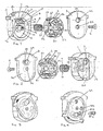
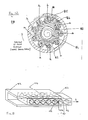
- a preferred magazine configuration is shown in Figures 1 and 2 and consists of a housing in the form of an outer case 1, an inner pellet carrier 2, a transparent cover plate 3, a coil spring 4 and a combined fixing screw/pivot 5.
- the outer case 1 has a circular recess 6, an exit hole 7 for the pellets, an integral pellet stop post 8 extending from the base 9 of the recess 6, spaced from the wall 10 of the recess 6 with one vertical face 11 of the pellet stop post 8 curved and aligned to match the adjacent edge 12 of the exit hole 7.
- An integral raised ridge 13 on the base 9 of the recess 6 is located between the post 8 and the adjacent wall 10.
- a further integral circular post 14 is located in the centre of the recess 6 and has a blind hole 15 at its top to receive the fixing screw 5.
- a small hole 16 In a shoulder at the base of the post 14 is a small hole 16 to receive one end of the spring 4.
- Lugs 17 provide a convenient grip and a viewing hole 18 passes through to the inner recess wall 10.
- On the face 19 of the case 1 is formed a shallow recess 20, open at one end.
- the inner pellet carrier 2 has a series of chambers 21 to receive pellets, and each of the chambers 21 is of part cylindrical configuration.
- An annular slot or channel 2 passes through the chambers 21, and is just high enough and wide enough to receive the post 8 without interference.
- the pellet carrier 2 is further formed with a central hole 23 with a small radially extending hole 24 off it, and an annular recess 25 on the edge of an end face 26 which terminates in a narrow spur 27 extending to the outer side 28.
- a similar annular recess 29 extends around the outer edge of the opposite end face 30 and ends in a narrow spur 31.
- Around the side 28 are provided a series of sequential numbers and/or markings 32, one adjacent to each chamber 21.
- the transparent cover plate 3 has an outline corresponding to that of the outer case 1, a countersunk central hole 33, a large, curved hole 34 and a stud 35 on an inside face 36, adjacent to the hole 34.
- the coil spring 4 has one end 37 perpendicular to its principal axis and the other end 38 parallel to it.
- the screw/pivot 5 is a countersunk, self-tapping screw.
- the magazine is assembled as follows;
- the spring 4 is inserted in the hole 23 in the pellet carrier 2 with its end 37 engaged in the small hole 24.
- the pellet carrier 2 is then fitted in the recess 6 of the case 1 so that the central post 14 passes through the spring 4 and the end 38 of the spring enters the small hole 16.
- the carrier 2 is rotated anti-clockwise against spring pressure so that the spur 31 passes over the ridge 13 and is then held against the ridge 13 by spring pressure.
- the cover 3 is then mounted on the post 14 using the screw 5 so that it is just able to turn freely and so that its outline is coincident with the outline of the case 1.
- the magazine is loaded as shown in Figure 3.
- the cover 3 is rotated in an anti-clockwise direction. After a short movement, the stud 35 on the cover 3 engages the spur 27 on the pellet carrier 2 and thus the carrier 2 is rotated with the cover 3, and the spring 4 is wound up. After the pellet carrier 2 has been rotated through nearly 360 o its spur 31 abuts the ridge 13 on the case 1 and further rotation is prevented.
- Figure 4 illustrates how the cover plate 3 is then rotated manually clockwise and further pellets 39A, 39B, 39C etc. are dropped through hole 34 into each successive carrier chamber 21A, 21B, 21C etc. until the required number have been loaded (which may be less than the maximum, if desired). The magazine will then be ready for inserting in the airgun.
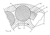
- Figure 5 is a magnified view of part of a section through the loaded magazine. It shows how the pellet 39, about to be fired, will always be located in exactly the same position, abutting the face 11 of the post 8. It also shows the excellent conformity ratio achieved between the walls 40 and 41 of the chamber 21 and pellet 9, and the abutment face 11 and pellet 39.
- the radius of the curved abutment face 11 is substantially the same as the maximum diameter of a typical pellet 39, thus producing a near-ideal conformity ratio equal to or very close to 1.
- the diameter of the chamber 21 is very slightly greater than that of the pellet 39.
- the two areas of contact between the walls 40 and 41 of the chamber 21 and the pellet 39 are substantially opposite the abutment face 11, and react the forces transmitted through the pellet 39 from the abutment face 11, which forces are transmitted from the stressed spring 4.
- the forces applied to the walls of the pellet 39 in the Figure 5 position are in a substantially triangular configuration.
- the spring force can be high enough to achieve rapid and reliable feeding and yet, because it is spread over a relatively large surface of the pellet, result in such acceptably low pressures that even a very soft and thin-walled lead diabolo pellet does not get distorted or damaged.
- the carrier 2 When the pellet 39 is removed, the carrier 2 will rotate clockwise under spring pressure, with the post 8 passing through the channel 22, until the next pellet is brought up against the abutment face 11. It will be appreciated that if, by chance, one chamber 21 has not received a pellet during loading, the carrier 2 will simply continue to rotate until the next full chamber 21 is reached.
- the relevant number or marking 32 will become visible through the viewing hole 18. Normally the number visible through hole 18 will indicate the number of chambers remaining to be brought up to the firing position, until the last chamber is reached, when a red or other suitable mark will be visible. Alternatively, only the last one or two chambers may carry an identifying mark.
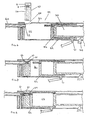
- Figure 6 shows a sectioned fixed-barrel air-rifle 49 in which the power source is a compressible spring 50, located behind the barrel, which may be a conventional metal coil spring or a sealed gas spring in accordance with U.K. Patent 2,084,704B.
- the spring 50 has been cocked by pressing back a stud 51, attached to a compression cylinder 52, by conventional cocking lever means (omitted for clarity) until the piston 53 is engaged by trigger mechanism 54.
- a space 55 is exposed within an outer cylinder 56 and a magazine 57 (for example, of the type illustrated in Figures 1 to 4) can be inserted into the space 55 through an aperture 58 in the outer cylinder 56.
- the shallow recess 20 On the rear face 19 of the magazine 57 is the shallow recess 20, which engages with a correspondingly shaped location guide 59 on the end of the barrel 60. This ensures that the edge 12 of the exit hole 7 of the magazine 57 which is, in effect, a continuation of the abutment face 11, is always accurately aligned with the barrel 60, and in precise register with the breech.
- Figure 7 shows the magazine 57 in place, with a pellet 61 lined up with the breech 62.
- the cocking lever (not shown) attached to the stud 51 is in the process of being brought forward and the compression cylinder 52 is moving in the direction of arrow B and is shown halfway towards the firing position.
- the compression cylinder 52 is fully forward, leaving compression chamber 63 fully open and a hollow combination probe and transfer port 64, mounted in the end cap of compression cylinder 52, has passed through magazine 57 and pushed the pellet 61 into the barrel.
- the probe 64 will seal the breech 62, for example, either by close fitting or by using an "O"-ring on either the probe or in the breech.
- the forward end of the probe 64 and the mouth of the breech 62 are correspondingly chamfered to provide interengaging surfaces that seal in a gas-tight manner when the probe 64 is in its forward position. The rifle is now ready to be fired.
- the compression cylinder 52 When the rifle is next cocked, the compression cylinder 52 will be forced back, carrying the piston 53 with it and compressing the spring 50.
- the probe 64 is also connected to the compression cylinder 52 and will therefore be withdrawn from the magazine 57. As soon as it is withdrawn, the spring-loaded pellet carrier 2 in the magazine 57 will be free to rotate and the next pellet will be brought into position, aligned with the breech.
- the transfer probe 64 repeatedly places each successive pellet 61 accurately in a predetermined position within the breech 62. Thus, as each pellet is fired from exactly the same position within the bore of the gun, high accuracy can be achieved.
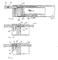
- Figures 10 and 11 show an alternative air-rifle configuration in which the high-pressure air or gas reaches the breech through a transfer port 65.
- the power source could be any suitable known system such as a compressible spring or springs running in a cylinder underneath and parallel to the barrel, or a liquid CO2 storage cylinder or a high-pressure, pre-charged air cylinder.
- operation of the trigger mechanism will release a metered quantity of the air or gas through the transfer port.
- a bolt 66 is solid with a short, small-diameter spigot 67 and is shown with an "O"-ring 68 immediately after shoulder 69 to seal the breech 62 and is shown in its rearward position, which enables the magazine 57 to be inserted or removed.
- Figure 11 shows the bolt 66 pushed forward through the magazine 57, carrying the pellet 61 out of the magazine 57 and far enough into the breech 62 so that the pellet 61 is just past the mouth 70 of the transfer port 65 and the bolt shoulder 69 is just behind the mouth 70.
- the bolt 66 will be lockable in its forward position by known means. Thus, when the rifle is fired, the high-pressure air or gas will be able to escape out of the mouth 70, flowing past spigot 67, and forcing the pellet 61 down the barrel.
- the bolt 66 may be arranged that it is left unlocked, or locked only for a short period. Then, the arrangement may be such that, when the high pressure air or gas escapes out of the mouth 70, it initially forces the pellet 61 down the barrel and out of the gun but, at the same time, begins to act on the bolt 66 to push it rearwardly out of engagement with the magazine 57 - for example, against spring pressure.
- the pellet carrier 2 may index to present the next pellet in line with the breech 62. Thereafter, the bolt 66 may be again inserted through the magazine 57 to push the next pellet 61 into the breech 62.
- the bolt 66 may be so actuated either manually, or as part of an automatic mechanism.
- the probe 64 shown in Figures 6 to 9 is, as mentioned above, preferably formed with a chamfered front end and a body diameter which is very slightly larger than the pellet diameter, and it is arranged to be in exact registration (that is, exactly co-axial) with the breech 62.
- each pellet 39 is retained in the chamber by co-operation between the pellet carrier 2, the outer case 1 and the cover 3, until such a time as the respective pellet 39 comes to abut against the post 8, to bring it into a position ready for loading.
- each pellet chamber 21 may have a diameter of 6.00 mm.
- the conformity ratio between the pellet 39 and the walls 40 and 41 of the chamber will be about 0.96.
- the conformity ratio between a pellet such as 39 and the walls of a pellet chamber such as 21 is greater than 0.90.
- the conformity ratio at the abutment surface 11 is high. Preferably, it is greater than 0.95, and can reach 1.0 with certain pellets.
- the conformity ratio of the chamber 21 were to be as high as 1.0, or nearly so, then difficulty could be experienced in inserting the pellet 39 into the chamber 21, unless the walls of the chamber 21 were made of a resilient material.
- Figure 12 shows, in diagrammatic form, an alternative configuration to that shown in Figures 1 to 4.
- the magazine 80 that is shown in Figure 12 comprises an outer casing 81 which is formed with a substantially circular recess 82, in which there is rotatably mounted a rotor 83, resiliently biassed in a clockwise direction by means of a coil spring 84.
- the outer casing 81 is formed with an inwardly projecting end stop 85.
- the rotor 83 is formed with a respective end stop 86.
- a cover (not shown for clarity) with a loading aperture will pivot on a central fixing (also not shown) and may be used to wind up the rotor 83 in a broadly similar manner to the cover 3 in Figures 1 and 2.
- the rotor is formed with a plurality of substantially semi-circular cut-outs, in each of which a respective airgun pellet A1 to A9 is seated.
- pellet A1 abuts against the end stop 85 which, as in the embodiment of Figures 1 to 4, has a curved abutment face of a diameter corresponding to that of the airgun pellets A1 to A9.
- a probe mechanism serves to push the airgun pellet A1 out of the magazine and into the breech of a respective airgun, ready for firing.
- the rotor 83 rotates under the force of the spring 84, to bring the next pellet A2 into abutment with the end stop 85.
- the loading and firing procedure may then be repeated, until the last pellet A9 has been loaded, whereupon the rotor end stop 86 comes to abut against the end stop 85 of the outer casing 81.
- the illustrated magazine 80 may operate in a manner broadly similar to that of the embodiment shown in Figures 1 to 4, although the actual configuration of the magazine components is slightly different.
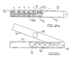
- Figure 13 is a simplified illustration of a straight magazine.
- FIG 13 only an outer case 42 and a pellet carrier 43 are shown, for convenience.
- the case 42 is formed with a channel and with a pellet exit hole 44 and, aligned with the edge of the exit hole 44, a pellet stop post 45.
- the carrier 43 is a rectangular strip having a series of pellet chambers 46 interconnected via a straight channel 47, which is just wide and long enough to clear the stop post 45.
- the carrier 43 is spring loaded to move in the direction of arrow A, relative to the case 42.
- pellet 48 will be the next pellet to be fired and, when it has gone, spring pressure will move the carrier 43 in the direction of arrow A until the post 45 comes into contact with the next pellet.
- Further details such as cover plate, spring, fastening means, registering means between the magazine and breech and other details have been omitted, for clarity. Nevertheless, it may be appreciated that the straight magazine as illustrated in Figure 13 may operate in a manner analogous to that shown in Figures 1 to 4. Therefore, a more detailed description of an example of operation of the straight magazine of Figure 13 will not be required.
- Figures 14A and 14B show another example of a straight magazine 90.
- a pellet carrier 92 is slideably mounted within an outer casing 91, and is resiliently biassed to the right (as seen) by means of a spring 93.
- the pellet carrier 92 is formed with five substantially semi-circular cut-outs 100, each of which is adapted to seat a respective airgun pellet A1 to A5.
- the outer casing 91 is formed with an end stop 95, having a curved abutment surface.
- the outer casing 91 is provided with a cover plate 96, which may pivot about a pivot point 97.
- the cover plate 96 is pivoted out of its closed position, to afford access to the inside of the magazine 90.
- the pellet carrier 92 is then moved manually to the leftmost position (as seen) and, keeping a finger over an outlet hole 99 of the outer casing 91, a first pellet is dropped into the position A1 shown in Figure 14A.
- the spring force urges the pellet A1 against the curved abutment surface of the end stop 95, to lock the pellet carrier in position, in a manner analogous to that of the circular magazine of Figures 1 to 4. Thereafter, the remaining four pellets can simply be dropped into the A2 to A5 positions.
- the cover plate 96 is then pivoted to its closed position, placing a probe hole 98 in register both with the breech of a respective airgun and the pellet exit hole 99 in the outer casing. It will of course be appreciated that the exit hole 99 is substantially in line with the A1 pellet position.
- the A2 pellet then comes into the ready position, and so on, until all of the pellets A1 to A5 have been used up.
- the magazine would tend to "grow” in length as the pellets are used up
- the length of the magazine always remains constant.
- the Figure 14 embodiment may also have the advantage that all of the moving parts may be substantially protected from snagging and the ingress of dirt.
- embodiments of the Figure 13 type which "grow" as the pellets are use up may have the advantage of allowing the user to monitor the number of pellets remaining in the magazine very readily indeed.
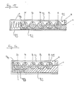
- Figures 15 and 16 illustrate yet alternative configurations of straight magazines, each of which "grows" in length as the pellets are used up.
- the embodiment of Figures 15 and 16 comprise parts which are substantially similar to those of the embodiment of Figure 14, although the configurations of the springs 93 are different and the cover plate (not shown for clarity) could be fixed permanently in position with its loading hole over pellet A1.
- the loading procedure for magazine embodiments similar to Figures 15 and 16 would be as follows.
- the user would hold the magazine with the loading hole facing upwards and a finger over the exit hole.
- Slight pressure will then be applied to the pellet carrier 92 at D to move the carrier slightly to the left and thus create sufficient space between the A5 recess and abutment surface of the end stop 95 to allow pellet A5 to be dropped in.
- Further pressure at D will bring recess A4 in line with the loading and exit holes and allow pellet A4 to be dropped in. This process will be repeated until the last pellet A1 is also dropped in.
- Pressure at point D can then be relaxed and pellet A1 will be gently gripped between the carrier 92 and the end stop 95 by spring pressure. Until then a finger must be kept over the exit hole to avoid the pellets simply dropping straight through the magazine as they are located.
- a pivotable (or slideable) cover plate may be provided, similar to the cover plate 96 of Figure 14, to allow the magazines of Figures 15 and 16 to be loaded in a manner similar to that of the magazine of Figure 14.
- the end stops 94 of the pellet carriers 92 are shaped to conform substantially to the curved abutment surface of the end stops 95 on the casings 91.
- the respective end stops 94 comes to abut closely against the corresponding curved surface of the end stops 95, to provide a firm abutment with negligible risk of jamming.
- the end stop 94 of the pellet carrier 92 shown in the Figure 14 embodiment may be formed in the same way as the embodiments of Figures 15 and 16.
- the arrangement of the Figure 14 embodiment may be such that, after the last pellet A5 has been loaded into the gun, the right hand end wall of the pellet carrier 92 (as seen in Figure 14) comes to abut against the corresponding inner end wall of the casing 91, thereby defining an end position of the pellet carrier 92.
- the illustrated embodiments may provide simple and extremely reliable magazines for use with airguns, which can be loaded with either or both ball or diabolo pellets of a calibre to suit the airgun and may be insensitive to the shape or length of the pellets. They may ensure that pellets may be fed directly into the breech and engaged in the rifling without distortion or damage. They may be extremely compact and easily removed or inserted.
- the magazines may be carried safely and reliably in the pocket, whilst being fully loaded. They may enable a user to ascertain rapidly whether any pellets are left, without removing the magazine from a respective gun.
- a particularly preferred feature of the illustrated embodiments is that they use the airgun pellets themselves as part of the indexing mechanism. That is, the indexing mechanism depends upon there being a pellet in the magazine, and the "next" pellet to be fired actually serves as part of the abutment means to place the pellet in register with the breech.
- the components of the magazine may be made of synthetic plastics materials, of metal, or other suitable materials.
Landscapes
- Engineering & Computer Science (AREA)
- General Engineering & Computer Science (AREA)
- Portable Nailing Machines And Staplers (AREA)
- Magnetic Resonance Imaging Apparatus (AREA)
- Jet Pumps And Other Pumps (AREA)
- Pens And Brushes (AREA)
- Measuring Leads Or Probes (AREA)
- Respiratory Apparatuses And Protective Means (AREA)
Applications Claiming Priority (2)
| Application Number | Priority Date | Filing Date | Title |
|---|---|---|---|
| GB888810674A GB8810674D0 (en) | 1988-05-06 | 1988-05-06 | Self-contained airgun magazine |
| GB8810674 | 1988-05-06 |
Publications (3)
| Publication Number | Publication Date |
|---|---|
| EP0341090A2 true EP0341090A2 (de) | 1989-11-08 |
| EP0341090A3 EP0341090A3 (en) | 1990-12-27 |
| EP0341090B1 EP0341090B1 (de) | 1994-11-09 |
Family
ID=10636420
Family Applications (1)
| Application Number | Title | Priority Date | Filing Date |
|---|---|---|---|
| EP89304607A Expired - Lifetime EP0341090B1 (de) | 1988-05-06 | 1989-05-08 | Magazin für Luftdruckwaffen |
Country Status (5)
| Country | Link |
|---|---|
| US (1) | US4986251A (de) |
| EP (1) | EP0341090B1 (de) |
| AT (1) | ATE114042T1 (de) |
| DE (1) | DE68919267D1 (de) |
| GB (1) | GB8810674D0 (de) |
Cited By (9)
| Publication number | Priority date | Publication date | Assignee | Title |
|---|---|---|---|---|
| GB2244121A (en) * | 1990-05-05 | 1991-11-20 | Bsa Guns | Air gun with rotary magazine |
| US5150701A (en) * | 1990-05-05 | 1992-09-29 | B.S.A. Guns (Uk) Limited | Air gun with rotary magazine |
| ES2191508A1 (es) * | 2000-03-24 | 2003-09-01 | Gamo Ind Sa | Dispositivo cargador de balines amovible en un arma de aire comprimido. |
| AT413760B (de) * | 2003-09-04 | 2006-05-15 | Walther Carl Gmbh | Magazin, sowie schusswaffe und verfahren zur betätigung einer schusswaffe |
| DE10359724B4 (de) * | 2003-09-04 | 2007-10-11 | Carl Walther Gmbh | Magazin, sowie Schusswaffe und Verfahren zur Betätigung einer Schusswaffe |
| EP2442063A2 (de) | 2010-10-15 | 2012-04-18 | BSA Guns (UK) Ltd. | Magazin |
| US20130008421A1 (en) * | 2011-07-05 | 2013-01-10 | Si Young Lee | Magazine rifle |
| US8434465B2 (en) | 2009-07-24 | 2013-05-07 | Crosman Corporation | Blowback assembly |
| WO2021167549A1 (en) * | 2020-02-20 | 2021-08-26 | Bahtiyar Tasyagan | A magazine which allows for changing the magazine without disrupting the firing position |
Families Citing this family (82)
| Publication number | Priority date | Publication date | Assignee | Title |
|---|---|---|---|---|
| US5660159A (en) * | 1991-11-18 | 1997-08-26 | Clayton; Richard A. | Airgun with rotary actuator |
| US5680853A (en) * | 1991-11-18 | 1997-10-28 | Clayton; Richard A. | Projectile launching apparatus |
| US5522374A (en) * | 1991-11-18 | 1996-06-04 | Clayton; Richard A. | Multi-shot air operated, projectile launcher |
| US5285766A (en) * | 1992-07-30 | 1994-02-15 | Crosman Corporation | Gun with removable rotary ammunition clip |
| US5544642A (en) * | 1995-07-14 | 1996-08-13 | G&G Innovations, Inc. | Multiple projectile blow gun magazine assembly |
| US5722383A (en) * | 1995-12-01 | 1998-03-03 | Tippmann Pneumatics, Inc. | Impeder for a gun firing mechanism with ammunition feeder and mode selector |
| GB2313654A (en) * | 1996-05-28 | 1997-12-03 | Frederick George Lambert | Single action cocking and loading air gun |
| US5845629A (en) * | 1997-03-25 | 1998-12-08 | Ratpak, Inc. | Hook and loop air gun and method therefor |
| US5954042A (en) * | 1997-11-10 | 1999-09-21 | Harvey; Daniel D. | Paintball loader |
| US6305367B1 (en) | 1999-02-26 | 2001-10-23 | Airgun Designs, Inc. | Hopper feeder |
| US6488019B2 (en) | 1999-02-26 | 2002-12-03 | Thomas G. Kotsiopoulos | Feeder for a paintball gun |
| US6467473B1 (en) * | 1999-02-26 | 2002-10-22 | Airgun Designs, Inc. | Paintball feeders |
| US6213110B1 (en) | 1999-12-16 | 2001-04-10 | Odyssey Paintball Products, Inc. | Rapid feed paintball loader |
| US6701907B2 (en) * | 1999-12-16 | 2004-03-09 | National Paintball Supply, Inc. | Spring loaded feed mechanism for paintball loader |
| USRE45986E1 (en) * | 1999-12-16 | 2016-04-26 | Gi Sportz Direct Llc | Spring loaded feed mechanism for paintball loader |
| US6470871B2 (en) * | 2000-03-24 | 2002-10-29 | Industrias, El Gamo, Sa | Small bullet loading device removably fitted to an air gun |
| US6347621B1 (en) | 2000-10-12 | 2002-02-19 | Christopher L. Guthrie | Projectile feed mechanism for a blowgun |
| RU2202754C2 (ru) * | 2000-12-13 | 2003-04-20 | Петросян Алексей Львович | Магазин для пневматического оружия, стреляющего пулями, и контейнер для пуль магазина пневматического оружия |
| US6820608B2 (en) * | 2001-01-09 | 2004-11-23 | New-Matics Licencing, Llc | Compressed gas-powered gun simulating the recoil of a conventional firearm |
| US6752137B2 (en) * | 2001-09-19 | 2004-06-22 | Fn Mfg Llc | Less-lethal launcher |
| US6530368B1 (en) * | 2002-04-05 | 2003-03-11 | Maruzen Company Limited | Air gun magazine and air gun having said magazine |
| US6889680B2 (en) * | 2002-04-12 | 2005-05-10 | National Paintball Supply, Inc. | Differential detection system for controlling feed of a paintball loader |
| US6837844B1 (en) * | 2002-05-14 | 2005-01-04 | Med-Tec Iowa, Inc. | Seed cartridge for radiation therapy |
| ITBS20020076A1 (it) * | 2002-08-29 | 2004-02-29 | Valtro Europ Srl | Caricatore a piu' tamburi in serie, particolarmente per armi ad aria |
| US7607424B2 (en) * | 2004-02-17 | 2009-10-27 | Planet Eclipse Limited | Electro-magnetically operated rotating projectile loader |
| US7343909B2 (en) * | 2004-04-28 | 2008-03-18 | Kee Action Sports I Llc | Mechanical drive assist for active feed paintball loader |
| US20050257783A1 (en) * | 2004-05-19 | 2005-11-24 | Tippmann Dennis J Jr | Valve arrangement |
| US7428899B2 (en) * | 2004-10-14 | 2008-09-30 | Kee Action Sports I Llc | Device for storing projectile balls and feeding them into the projectile chamber of a gun |
| US7234456B2 (en) | 2004-10-14 | 2007-06-26 | Kee Action Sports | Device for feeding balls into the ball chamber of a handgun |
| US20070017495A1 (en) * | 2004-10-14 | 2007-01-25 | Heddies Andresen | Procedure and device for feeding balls into the projectile chamber of a handgun |
| US7694669B2 (en) | 2004-12-08 | 2010-04-13 | Kee Action Sports I, Llc | Paintball loader feed mechanism |
| US7222573B2 (en) * | 2005-04-01 | 2007-05-29 | Pontieri James M | Aerodynamic air gun projectile |
| DE102005035915B3 (de) | 2005-07-28 | 2006-08-17 | Kaeseler, Werner, Dipl.-Ing. | Punktschweißkappenwechsler |
| US20070056573A1 (en) * | 2005-08-05 | 2007-03-15 | National Paintball Supply, Inc. | Paintball agitator with anti-jam mechanism |
| US7395763B1 (en) * | 2005-09-02 | 2008-07-08 | Vari Daniel P | System and method for introducing a cleaning element into the barrel of a paintball marker |
| US20070062506A1 (en) * | 2005-09-13 | 2007-03-22 | National Paintball Supply, Inc. | Clutch and detection means for paintball marker loader |
| US7921835B2 (en) | 2005-09-15 | 2011-04-12 | Kee Action Sports I Llc | Wireless projectile loader system |
| CN101506612A (zh) * | 2005-10-06 | 2009-08-12 | 即动运动有限公司 | 自调节彩弹搅拌器系统 |
| CN101317070A (zh) | 2005-10-11 | 2008-12-03 | 即动运动有限公司 | 彩弹装载器的磁性驱动旁通系统 |
| WO2007139934A2 (en) * | 2006-05-25 | 2007-12-06 | Kee Action Sports I Llc | Self-regulating valve assembly |
| WO2009015393A2 (en) * | 2007-07-26 | 2009-01-29 | Kee Actions Sports I Llc | Paintball loader removable drive system |
| USD584776S1 (en) | 2007-10-24 | 2009-01-13 | Kee Action Sports I Llc | Paintball loader body |
| TW200923313A (en) * | 2007-11-30 | 2009-06-01 | Maruzen Co Ltd | Magazine for air gun having rotary clip |
| US8291894B2 (en) * | 2008-04-24 | 2012-10-23 | Barwick Jr Billie John | Loading pellets in pellet guns |
| USD604371S1 (en) | 2008-08-29 | 2009-11-17 | Kee Action Sports I Llc | Anti-jam mechanism for a paintball loader |
| US20110000473A1 (en) * | 2009-07-01 | 2011-01-06 | Michael Perron | Snowball Gun Toy |
| US8402958B2 (en) * | 2009-08-21 | 2013-03-26 | Hasbro, Inc. | Toy dart magazine apparatus |
| DE202011100464U1 (de) | 2011-05-10 | 2011-08-23 | Theo Hegmans | Diabolomagazin zur Umrüstung druckgasbetriebener Einzelladerwaffen auf Repetierbetrieb |
| KR101310770B1 (ko) * | 2011-07-11 | 2013-09-25 | 이시영 | 자동 회전 탄창 및 이를 구비하는 다연발 공기총 |
| ES2721255T3 (es) | 2013-06-21 | 2019-07-30 | Kee Action Sports I Llc | Pistola de gas comprimido que presenta un mecanismo de alimentación de proyectiles interno incorporado |
| WO2015013610A1 (en) * | 2013-07-26 | 2015-01-29 | Mattel Inc. | Magazine for projectile launcher |
| US9429385B1 (en) * | 2015-02-11 | 2016-08-30 | Scott William Allen | Drum magazine for loading paintballs and shaped projectiles into a magazine-fed firearm |
| US9335116B1 (en) * | 2015-03-30 | 2016-05-10 | Ho-Sheng Wei | Cylinder accommodation magazine and toy gun using the same |
| KR101694814B1 (ko) * | 2015-04-14 | 2017-01-10 | 박승철 | 공기총의 분할형 탄창 |
| CN105403101A (zh) * | 2015-12-17 | 2016-03-16 | 浙江新华体育器材制造有限公司 | 一种气枪弹轮 |
| CN205403585U (zh) * | 2016-01-15 | 2016-07-27 | 中山市新山禾技术服务有限公司 | 一种新型气压式气枪钢弹自动上弹器 |
| US20190195594A1 (en) * | 2016-11-30 | 2019-06-27 | Umarex Usa, Inc. | Cocking and Loading Apparatus for Repeater Air Rifle |
| US10197355B2 (en) * | 2016-11-30 | 2019-02-05 | Umarex Usa, Inc. | Cocking and loading apparatus for repeater air rifle |
| US10267593B2 (en) * | 2016-11-30 | 2019-04-23 | Umarex Usa, Inc. | Cocking and loading apparatus for repeater air rifle |
| TWM542131U (zh) * | 2016-12-09 | 2017-05-21 | Kien Well Toy Industrial Co Ltd | 玩具槍彈倉之結構改良 |
| US10605562B2 (en) | 2017-09-25 | 2020-03-31 | Umarex Usa, Inc. | Linear chamber magazine |
| US11703302B2 (en) * | 2017-09-25 | 2023-07-18 | Umarex Usa, Inc. | Dynamic sealing chamber magazine |
| US10371473B1 (en) * | 2018-06-07 | 2019-08-06 | Ho-Sheng Wei | Magazine structure for a toy gun |
| US11156416B2 (en) * | 2018-06-08 | 2021-10-26 | Gamo Outdoor, S.L. | System for loading pellets |
| US11098976B2 (en) * | 2019-02-20 | 2021-08-24 | Crosman Corporation | Airgun projectile carrier |
| US10996021B2 (en) * | 2019-05-14 | 2021-05-04 | Calvin Kittridge Colby | Air-powered shot device and components for disabling a hard-body insect |
| US10883784B1 (en) * | 2019-06-10 | 2021-01-05 | Umarex Usa, Inc. | Air gun magazine safety system |
| US10690438B1 (en) * | 2019-06-28 | 2020-06-23 | Ho-Sheng Wei | Toy gun with slide stopping mechanism |
| ES2964582T3 (es) * | 2019-08-02 | 2024-04-08 | Gamo Outdoor Sl | Cargador para balines de rifles y pistolas de aire comprimido |
| US11353279B2 (en) * | 2019-10-01 | 2022-06-07 | Easebon Services Limited | Toy projectile launcher and method of using same |
| WO2021080523A1 (en) * | 2019-10-22 | 2021-04-29 | Bahtiyar Tasyagan | Easily chargeable and adjustable magazine |
| USD961002S1 (en) | 2019-12-30 | 2022-08-16 | Kore Outdoor (Us), Inc. | Projectile loader |
| USD988458S1 (en) * | 2020-01-22 | 2023-06-06 | Crosman Corporation | Airgun magazine |
| US11226168B2 (en) * | 2020-01-22 | 2022-01-18 | Crosman Corporation | Airgun magazine |
| US11353282B2 (en) | 2020-01-22 | 2022-06-07 | Crosman Corporation | Multi-shot airgun |
| CN111750737B (zh) * | 2020-07-16 | 2025-05-23 | 绍兴市岭峰气枪制造有限公司 | 一种自动上弹结构 |
| US12385715B2 (en) | 2020-09-30 | 2025-08-12 | Kore Outdoor (Us), Inc. | Compressed gas projectile launching devices |
| USD992671S1 (en) | 2020-10-08 | 2023-07-18 | Canadian Imperial Bank Of Commerce, As Agent | Projectile launcher and loader |
| US11680769B1 (en) * | 2022-01-01 | 2023-06-20 | Douglas C. Hepler | Air gun magazine loading device |
| US12467714B2 (en) * | 2023-03-08 | 2025-11-11 | Easebon Services Limited | Air piston assembly and toy launcher including the same |
| US12474138B2 (en) * | 2023-06-19 | 2025-11-18 | Banza Stamping Industry Corporation | Spring-loaded piercing mechanism for a pressurized gas vessel |
| US20240418475A1 (en) * | 2023-06-19 | 2024-12-19 | Banza Stamping Industry Corp | Pressurized gas vessel and piercing mechanism |
Family Cites Families (19)
| Publication number | Priority date | Publication date | Assignee | Title |
|---|---|---|---|---|
| GB190604622A (en) * | 1906-02-26 | 1906-12-13 | Arthur Harry Butler | Magazine Loading for Air Rifles |
| US926546A (en) * | 1908-02-24 | 1909-06-29 | Joseph Henry Cox | Magazine air-gun. |
| US1328929A (en) * | 1918-06-12 | 1920-01-27 | H K Toy & Novelty Co | Toy machine-gun |
| US1677810A (en) * | 1927-07-15 | 1928-07-17 | Richard T Bond | Magazine for air guns |
| US1816091A (en) * | 1927-12-13 | 1931-07-28 | Schmeisser Hugo | Repeating air gun |
| GB302279A (de) * | 1927-12-13 | 1930-01-30 | Hans Schmeisser | |
| US2303017A (en) * | 1941-03-17 | 1942-11-24 | G Man Six Shooter Inc | Toy |
| US2609811A (en) * | 1948-12-03 | 1952-09-09 | Stephen E Laszlo | Magazine loader for air guns |
| US2713859A (en) * | 1953-02-09 | 1955-07-26 | Elmer H Bradfield | Slidable magazine for fluid pressure gun |
| US3239959A (en) * | 1964-03-24 | 1966-03-15 | Sturm Ruger & Co | Removable magazine for repeating gun |
| US3913553A (en) * | 1971-03-16 | 1975-10-21 | Victor Comptometer Corp | Air gun with removable projectile holding means |
| US3741189A (en) * | 1971-03-29 | 1973-06-26 | Crosman Arms Co Inc | Gas operated pellet gun with removable clip loader |
| US3782359A (en) * | 1971-03-29 | 1974-01-01 | Coleman Co | Removable clip with rotary projectile cylinder for a gun |
| JPS4915545A (de) * | 1972-05-31 | 1974-02-12 | ||
| DE3040924C2 (de) * | 1980-10-30 | 1985-11-21 | Mayer & Grammelspacher Dianawerk, 7550 Rastatt | Druckluftwaffe mit einem Geschoßmagazin |
| US4487103A (en) * | 1982-06-24 | 1984-12-11 | Atchisson Maxwell G | Drum magazine |
| GB2152646B (en) * | 1984-01-13 | 1988-01-06 | Roy Hutchison | Air weapons |
| DE3505443A1 (de) * | 1985-02-16 | 1986-08-21 | Fritz Barthelmes KG, 7920 Heidenheim | Luftdruckwaffe |
| DD253474A1 (de) * | 1986-10-17 | 1988-01-20 | Thaelmann Fahrzeug Jagdwaffen | Magazin fuer luftdruckwaffen |
-
1988
- 1988-05-06 GB GB888810674A patent/GB8810674D0/en active Pending
-
1989
- 1989-05-05 US US07/348,257 patent/US4986251A/en not_active Expired - Fee Related
- 1989-05-08 EP EP89304607A patent/EP0341090B1/de not_active Expired - Lifetime
- 1989-05-08 AT AT89304607T patent/ATE114042T1/de not_active IP Right Cessation
- 1989-05-08 DE DE68919267T patent/DE68919267D1/de not_active Expired - Lifetime
Cited By (13)
| Publication number | Priority date | Publication date | Assignee | Title |
|---|---|---|---|---|
| US5150701A (en) * | 1990-05-05 | 1992-09-29 | B.S.A. Guns (Uk) Limited | Air gun with rotary magazine |
| GB2244121B (en) * | 1990-05-05 | 1994-03-30 | Bsa Guns | Air gun with rotary magazine |
| GB2244121A (en) * | 1990-05-05 | 1991-11-20 | Bsa Guns | Air gun with rotary magazine |
| ES2191508A1 (es) * | 2000-03-24 | 2003-09-01 | Gamo Ind Sa | Dispositivo cargador de balines amovible en un arma de aire comprimido. |
| AT413760B (de) * | 2003-09-04 | 2006-05-15 | Walther Carl Gmbh | Magazin, sowie schusswaffe und verfahren zur betätigung einer schusswaffe |
| DE10359724B4 (de) * | 2003-09-04 | 2007-10-11 | Carl Walther Gmbh | Magazin, sowie Schusswaffe und Verfahren zur Betätigung einer Schusswaffe |
| US8434465B2 (en) | 2009-07-24 | 2013-05-07 | Crosman Corporation | Blowback assembly |
| EP2442063A2 (de) | 2010-10-15 | 2012-04-18 | BSA Guns (UK) Ltd. | Magazin |
| EP2442063A3 (de) * | 2010-10-15 | 2012-11-21 | BSA Guns (UK) Ltd. | Magazin |
| GB2484536A (en) * | 2010-10-15 | 2012-04-18 | Bsa Guns Uk Ltd | Magazine |
| US20130008421A1 (en) * | 2011-07-05 | 2013-01-10 | Si Young Lee | Magazine rifle |
| US8931467B2 (en) * | 2011-07-05 | 2015-01-13 | Si Young Lee | Magazine rifle |
| WO2021167549A1 (en) * | 2020-02-20 | 2021-08-26 | Bahtiyar Tasyagan | A magazine which allows for changing the magazine without disrupting the firing position |
Also Published As
| Publication number | Publication date |
|---|---|
| DE68919267D1 (de) | 1994-12-15 |
| EP0341090B1 (de) | 1994-11-09 |
| EP0341090A3 (en) | 1990-12-27 |
| GB8810674D0 (en) | 1988-06-08 |
| US4986251A (en) | 1991-01-22 |
| ATE114042T1 (de) | 1994-11-15 |
Similar Documents
| Publication | Publication Date | Title |
|---|---|---|
| US4986251A (en) | Airgun magazine | |
| US4034644A (en) | Firearm and magazine construction | |
| CA1051702A (en) | Revolver-type repeating gun | |
| US7025052B2 (en) | Compressed gas-powdered gun simulating the recoil of a conventional firearm | |
| US3612026A (en) | Gas-operated revolver with rotatable magazine | |
| US3741189A (en) | Gas operated pellet gun with removable clip loader | |
| US3726266A (en) | Gas-operated multiple shot projectile firing device | |
| US7380361B2 (en) | System and method for increased magazine capacity for a firearm | |
| US5850826A (en) | Paint ball blow gun device | |
| US3782359A (en) | Removable clip with rotary projectile cylinder for a gun | |
| US5119575A (en) | Rotary magazine for firearms | |
| US4905395A (en) | Increased capacity magazine for firearm | |
| US2980096A (en) | Gas powered revolver | |
| US7562478B1 (en) | Firearm conversion system and caliber reducer with hammer safety lock | |
| US5220115A (en) | Dual cylinder revolver | |
| US5156137A (en) | Projectile launcher | |
| US3997994A (en) | Shoulder arm with swivel breech member | |
| US4862621A (en) | Device for facilitating loading of a shotgun | |
| EP0044632A1 (de) | Bedienungsmechanismus für Handfeuerwaffen | |
| US3547095A (en) | Gas-operated revolver | |
| US3270455A (en) | Semi-automatic repeating flare pistol | |
| EP2442063A2 (de) | Magazin | |
| US4686786A (en) | Cartridge loading and feeding arrangement for explosive charge operated device | |
| EP0044165B1 (de) | Feuerwaffen mit drehbaren Magazinen | |
| EP3704436B1 (de) | Dreisäulige magazinstruktur für schusswaffen |
Legal Events
| Date | Code | Title | Description |
|---|---|---|---|
| PUAI | Public reference made under article 153(3) epc to a published international application that has entered the european phase |
Free format text: ORIGINAL CODE: 0009012 |
|
| AK | Designated contracting states |
Kind code of ref document: A2 Designated state(s): AT CH DE ES FR GB IT LI |
|
| PUAL | Search report despatched |
Free format text: ORIGINAL CODE: 0009013 |
|
| AK | Designated contracting states |
Kind code of ref document: A3 Designated state(s): AT CH DE ES FR GB IT LI |
|
| 17P | Request for examination filed |
Effective date: 19910909 |
|
| 17Q | First examination report despatched |
Effective date: 19920814 |
|
| GRAA | (expected) grant |
Free format text: ORIGINAL CODE: 0009210 |
|
| AK | Designated contracting states |
Kind code of ref document: B1 Designated state(s): AT CH DE ES FR GB IT LI |
|
| PG25 | Lapsed in a contracting state [announced via postgrant information from national office to epo] |
Ref country code: IT Free format text: LAPSE BECAUSE OF FAILURE TO SUBMIT A TRANSLATION OF THE DESCRIPTION OR TO PAY THE FEE WITHIN THE PRE;WARNING: LAPSES OF ITALIAN PATENTS WITH EFFECTIVE DATE BEFORE 2007 MAY HAVE OCCURRED AT ANY TIME BEFORE 2007. THE CORRECT EFFECTIVE DATE MAY BE DIFFERENT FROM THE ONE RECORDED.SCRIBED TIME-LIMIT Effective date: 19941109 Ref country code: AT Effective date: 19941109 Ref country code: LI Effective date: 19941109 Ref country code: CH Effective date: 19941109 Ref country code: FR Effective date: 19941109 Ref country code: ES Free format text: THE PATENT HAS BEEN ANNULLED BY A DECISION OF A NATIONAL AUTHORITY Effective date: 19941109 |
|
| REF | Corresponds to: |
Ref document number: 114042 Country of ref document: AT Date of ref document: 19941115 Kind code of ref document: T |
|
| REF | Corresponds to: |
Ref document number: 68919267 Country of ref document: DE Date of ref document: 19941215 |
|
| PG25 | Lapsed in a contracting state [announced via postgrant information from national office to epo] |
Ref country code: DE Effective date: 19950210 |
|
| REG | Reference to a national code |
Ref country code: CH Ref legal event code: PL |
|
| EN | Fr: translation not filed | ||
| PLBE | No opposition filed within time limit |
Free format text: ORIGINAL CODE: 0009261 |
|
| STAA | Information on the status of an ep patent application or granted ep patent |
Free format text: STATUS: NO OPPOSITION FILED WITHIN TIME LIMIT |
|
| 26N | No opposition filed | ||
| REG | Reference to a national code |
Ref country code: GB Ref legal event code: IF02 |
|
| REG | Reference to a national code |
Ref country code: GB Ref legal event code: 732E |
|
| PGFP | Annual fee paid to national office [announced via postgrant information from national office to epo] |
Ref country code: GB Payment date: 20080421 Year of fee payment: 20 |
|
| REG | Reference to a national code |
Ref country code: GB Ref legal event code: PE20 Expiry date: 20090507 |
|
| PG25 | Lapsed in a contracting state [announced via postgrant information from national office to epo] |
Ref country code: GB Free format text: LAPSE BECAUSE OF EXPIRATION OF PROTECTION Effective date: 20090507 |