EP0341070A2 - Steuereinrichtung für einen Kran mit Fahrer - Google Patents
Steuereinrichtung für einen Kran mit Fahrer Download PDFInfo
- Publication number
- EP0341070A2 EP0341070A2 EP89304521A EP89304521A EP0341070A2 EP 0341070 A2 EP0341070 A2 EP 0341070A2 EP 89304521 A EP89304521 A EP 89304521A EP 89304521 A EP89304521 A EP 89304521A EP 0341070 A2 EP0341070 A2 EP 0341070A2
- Authority
- EP
- European Patent Office
- Prior art keywords
- control
- control unit
- cab
- operator
- crane
- Prior art date
- Legal status (The legal status is an assumption and is not a legal conclusion. Google has not performed a legal analysis and makes no representation as to the accuracy of the status listed.)
- Withdrawn
Links
Images


Classifications
-
- B—PERFORMING OPERATIONS; TRANSPORTING
- B66—HOISTING; LIFTING; HAULING
- B66C—CRANES; LOAD-ENGAGING ELEMENTS OR DEVICES FOR CRANES, CAPSTANS, WINCHES, OR TACKLES
- B66C13/00—Other constructional features or details
- B66C13/52—Details of compartments for driving engines or motors or of operator's stands or cabins
- B66C13/54—Operator's stands or cabins
- B66C13/56—Arrangements of handles or pedals
-
- B—PERFORMING OPERATIONS; TRANSPORTING
- B66—HOISTING; LIFTING; HAULING
- B66F—HOISTING, LIFTING, HAULING OR PUSHING, NOT OTHERWISE PROVIDED FOR, e.g. DEVICES WHICH APPLY A LIFTING OR PUSHING FORCE DIRECTLY TO THE SURFACE OF A LOAD
- B66F9/00—Devices for lifting or lowering bulky or heavy goods for loading or unloading purposes
- B66F9/06—Devices for lifting or lowering bulky or heavy goods for loading or unloading purposes movable, with their loads, on wheels or the like, e.g. fork-lift trucks
- B66F9/075—Constructional features or details
- B66F9/20—Means for actuating or controlling masts, platforms, or forks
-
- H—ELECTRICITY
- H01—ELECTRIC ELEMENTS
- H01H—ELECTRIC SWITCHES; RELAYS; SELECTORS; EMERGENCY PROTECTIVE DEVICES
- H01H9/00—Details of switching devices, not covered by groups H01H1/00 - H01H7/00
- H01H9/02—Bases, casings, or covers
- H01H9/0214—Hand-held casings
-
- H—ELECTRICITY
- H01—ELECTRIC ELEMENTS
- H01H—ELECTRIC SWITCHES; RELAYS; SELECTORS; EMERGENCY PROTECTIVE DEVICES
- H01H21/00—Switches operated by an operating part in the form of a pivotable member acted upon directly by a solid body, e.g. by a hand
- H01H21/02—Details
- H01H21/18—Movable parts; Contacts mounted thereon
- H01H21/36—Driving mechanisms
- H01H21/50—Driving mechanisms with indexing or latching means, e.g. indexing by ball and spring; with means to ensure stopping at intermediate operative positions
-
- H—ELECTRICITY
- H01—ELECTRIC ELEMENTS
- H01H—ELECTRIC SWITCHES; RELAYS; SELECTORS; EMERGENCY PROTECTIVE DEVICES
- H01H2225/00—Switch site location
- H01H2225/008—Two different sites for one circuit, e.g. for safety
-
- H—ELECTRICITY
- H01—ELECTRIC ELEMENTS
- H01H—ELECTRIC SWITCHES; RELAYS; SELECTORS; EMERGENCY PROTECTIVE DEVICES
- H01H2239/00—Miscellaneous
- H01H2239/066—Duplication of control panel, e.g. duplication of some keys
-
- H—ELECTRICITY
- H01—ELECTRIC ELEMENTS
- H01H—ELECTRIC SWITCHES; RELAYS; SELECTORS; EMERGENCY PROTECTIVE DEVICES
- H01H2300/00—Orthogonal indexing scheme relating to electric switches, relays, selectors or emergency protective devices covered by H01H
- H01H2300/026—Application dead man switch: power must be interrupted on release of operating member
-
- H—ELECTRICITY
- H01—ELECTRIC ELEMENTS
- H01H—ELECTRIC SWITCHES; RELAYS; SELECTORS; EMERGENCY PROTECTIVE DEVICES
- H01H9/00—Details of switching devices, not covered by groups H01H1/00 - H01H7/00
- H01H9/20—Interlocking, locking, or latching mechanisms
- H01H9/26—Interlocking, locking, or latching mechanisms for interlocking two or more switches
Definitions
- This invention relates to a control unit for a man rider crane adapted for use in warehousing systems.
- a man rider crane comprises a main chassis designed to run along each aisle on rails and has an operators cab mounted on the chassis so as to be movable vertically. The control of the movement of the crane along the aisles and the vertical movement of the cab is controlled by the operator when he is in the cab. Thus, the operator can position himself at a desired position in an aisle and adjacent a desired shelf in the vertical direction to enable him to load and unload items from the desired shelf.
- the present invention seeks to provide a control unit for such man rider cranes which ensures that the crane and/or cab cannot be moved unless the operator is in a predetermined, safe, position.
- a control unit for a man rider crane comprising a chassis movable horizontally and an operators cab movable in a vertical direction relative to the chassis, the control unit being a pendant control adapted to depend from an overhead part of the cab and being movable between a stowed position clear of an operator and a depending operative position, the control having two manually operable control members operable respectively to control the positioning of the crane and the operators cab relative thereto, the control members being such that movement of the cab and/or crane is possible only when the operator moves both of the control members from a neutral position to which the members are resilient biassed.
- a pair of safety switches is provided on the pendant control unit these switches being biassed to the off position to prevent movement of the cab or crane unless both switches are simultaneously moved manually to the on position by the second operator.
- a further key operable switch is provided to convert the cab for one man or two man operation, as the case maybe.
- the crane has a main chassis part 1 carrying rollers 2 which run on rails 3 laid in the aisles along which the crane travels.
- the crane has a superstructure 4 which has two vertical posts 5 and 6 providing guides for a vertically movable cab 7.
- the cab 7 is guided on the posts 5 and 6 by known means and it is connected to a motor 8 by a cable arrangement 9 through which its height can be adjusted as desired.
- the cab consists of a base platform 10, a roof superstructure 11, with a guide rail 12 to prevent the operator falling off the cab. Parts, 12a and 12b of the cab guide rail are movable to allow the operator to enter and leave the cab.
- the control of the vertical movement of the cab on the posts 5 and 6 and the horizontal movement of the entire crane on the rails 3 is controlled by an operator on the cab by means of a pendant control unit 13. Details of the pendant control unit are shown in greater detail in Figures 2, 3 and 4.
- the unit 13 is pivotally mounted to the roof 11 of the cab so as to pivot between a stowed position 14 shown in outline, where the unit is parallel to the roof clear of the roof and a depending operative position 15 where control members on the unit may be manually held by the operator.
- control unit includes a second set of controls which consist of a control handle containing two manually operable safety switches (not shown).
- the safety switches comprise manually operable switches placed on each side of a handle bar and are biassed to the off position to disable the control circuitry to thereby prevent movement of the cab and crane by the other operator.
- the safety switches must be held manually in the on position to enable movement of the crane to be controlled by the first operator to thereby ensure that the second operator remains in a safe place during movement.
- a key operable switch is located elsewhere on the cab to disable or override the effect of the safety switches for the second operator when no second operator is on the cab.
- FIG. 2 there is shown the lower most part of the pendant unit 13 with the front cover removed to show part of the mechanism.
- Figure 3 shows a similar view of this part of the control unit in an exploded form.
- the control unit has a handle bar 17 which is held by the operator with his hands positioned so that he can operate two switches 18 and 19 with his thumbs.
- the two switches 18 and 19 are biassed to a neutral position (stage 5 shown in Figure 4a) by springs 20, shown in Figure 3.
- the construction of the switches 18 and 19 is essentially identical so that the two halves of the unit are identical and therefore only one will be described for simplicity.
- the lever 19 is biassed to the neutral position by a torsion spring 20 which is concentrically mounted on a shaft 21 to which the lever 19 is connected so as to be rotationally fast thereon.
- the switch lever 19 has a further member 22 pivotally fast thereto which has a outwardly extending limb 23 which engages between the ends of the torsion spring 20.
- the spring 20 is placed under tension and this tension serves to bias the lever to the neutral position.
- Each of the levers 18 and 19 is movable upwardly or downwardly through four distinct positions. The positions are determined by a detent arrangement consisting of a series of detents 24 on the member 22 which are engaged by a detent pin 25 on a lever 26 which is pivotally mounted on the body of the control unit.
- a spring 27 serves to bias the lever 26 so that detent pin 25 is biassed into engagement with the detents 24.
- the detents are shaped so as to have a gentle ramp in the direction in which the member 19 is pushed into one of the selective positions by the operator the other face of the detent being much steeper to provide a positive abutment to define the position, so that the operator has to make a positive pressure movement to move into the next stage.
- the shallowness of the lead-in ramp is not sufficient to prevent the spring 20 from returning the lever to the neutral position as soon as the member 19 is manually released by the operator.
- a series of micro-switches arranged in two banks 28 and 29 are associated with each of the levers 18 and 19.
- the micro-switches associated with the lever 19 are numbered 1 to 8 and those associated with the lever 18 are numbered a to h.
- Pivotable movement of the members 18 and 19 causes corresponding rotation of a series of cams 30, each cam controlling two of the micro-switches, there being four cams controlled by each of the two members.
- the horizontal movement of the crane is controlled by the switch 19 and the vertical movement by the member 18. It is impossible to move either the cab or the crane by operation of its associated member unless the other member is simultaneously moved also, at least into its first position to close the first of its micro-swtiches.
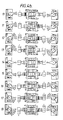
- This position is shown as stage 1 in Figure 4a in which both of the members 18 and 19 have been moved to their first position. When in this position no movement of the cab or crane takes place but the system is primed to enable one or both to be moved. This ensures that the operator is always in a known safe position with both hands occupied before the cab or crane can be moved. From this position either the cab or crane or both can be moved.
- stage 2 of Figure 4a for example, the cab is being moved up at its slowest speed and the crane is being moved horizontally at its slowest speed in one direction.
- Stage 3 shows an intermediate speed stage for both the vertical cab movement and horizontal movement of the crane whilst stage 4 shows the highest speed.
- Stage 5 shows the neutral hands off position.
- Stage 6 shows the priming position for movement in the reverse direction when the levers 18 and 19 are moved downwardly.
- stage 7 shows the cab being moved downwardly at its slowest speed and the crane being moved horizontally at its slowest speed in the opposite direction to that shown in stage 2. It can be seen that in each stage the appropriate micro-switches 30 are closed.
- Stages 10 to 18 show other permutations in the movement of the cab and crane and it will be seen that the crane can move in each direction at slow intermediate and fast speeds whilst the cab can move vertically at slow intermediate and fast speeds either up or down simultaneously with the movement of the crane.
- the safety of the operator, or both operators where two are present on the platform at the same time, is ensured whilst enabling the maximum efficiency of movement of the cab and crane.
- the pendant unit When the control unit is not in use, as when the operator is picking up from the racks and/or loading pallets onto the platform the pendant unit can be raised up to the stowed position out of the way of the operator.
- Two gas struts (not shown) are provided to assist in the movement of the pendant unit. Provision is also made for the vertical adjustment of the pendant over a range of 100 mm to compensate for the different heights of the operators to enable each operator to position the control unit at the most comfortable height.
- the station for the second operator is generally similar to that described in Figures 2 and 3.
- the second operator will be provided with a similar handle bar arrangement and two switches but instead of these switches comprising control switches they are simple on/off safety switches which must be held closed by the second operator before the first operator can initiate movement of the cab and/or crane.
Landscapes
- Engineering & Computer Science (AREA)
- Transportation (AREA)
- Structural Engineering (AREA)
- Mechanical Engineering (AREA)
- Chemical & Material Sciences (AREA)
- Combustion & Propulsion (AREA)
- Civil Engineering (AREA)
- Life Sciences & Earth Sciences (AREA)
- Geology (AREA)
- Jib Cranes (AREA)
Applications Claiming Priority (2)
| Application Number | Priority Date | Filing Date | Title |
|---|---|---|---|
| GB888810464A GB8810464D0 (en) | 1988-05-04 | 1988-05-04 | Control unit for man-rider crane |
| GB8810464 | 1988-05-04 |
Publications (2)
| Publication Number | Publication Date |
|---|---|
| EP0341070A2 true EP0341070A2 (de) | 1989-11-08 |
| EP0341070A3 EP0341070A3 (de) | 1990-08-08 |
Family
ID=10636292
Family Applications (1)
| Application Number | Title | Priority Date | Filing Date |
|---|---|---|---|
| EP89304521A Withdrawn EP0341070A3 (de) | 1988-05-04 | 1989-05-04 | Steuereinrichtung für einen Kran mit Fahrer |
Country Status (2)
| Country | Link |
|---|---|
| EP (1) | EP0341070A3 (de) |
| GB (2) | GB8810464D0 (de) |
Cited By (2)
| Publication number | Priority date | Publication date | Assignee | Title |
|---|---|---|---|---|
| FR2688959A1 (fr) * | 1992-01-24 | 1993-09-24 | Fusilier Jean Marie | Dispositif manipulateur unitaire pour la telecommande sans fil d'une unite fonctionnelle. |
| EP0910103A3 (de) * | 1997-10-17 | 2000-10-11 | Matsushita Electric Industrial Co., Ltd. | Unterbedienungstafel zur Verwendung in Unterhaltsarbeiten, und Verfahren zum Hantieren dieser Unterbedienungstafel |
Family Cites Families (4)
| Publication number | Priority date | Publication date | Assignee | Title |
|---|---|---|---|---|
| DE1026942B (de) * | 1953-11-20 | 1958-03-27 | Maschf Augsburg Nuernberg Ag | Haengeschaltgeraet zur Steuerung von Kranen |
| US3033392A (en) * | 1960-03-21 | 1962-05-08 | Western Electric Co | Stock storage and selection system |
| US3237780A (en) * | 1964-10-14 | 1966-03-01 | Ingersoll Rand Co | Height adjustable pendent control |
| AT354937B (de) * | 1978-05-03 | 1980-02-11 | Locker Ernst | Regalbedienungsgeraet |
-
1988
- 1988-05-04 GB GB888810464A patent/GB8810464D0/en active Pending
-
1989
- 1989-05-04 EP EP89304521A patent/EP0341070A3/de not_active Withdrawn
- 1989-05-04 GB GB8910245A patent/GB2221017A/en not_active Withdrawn
Cited By (3)
| Publication number | Priority date | Publication date | Assignee | Title |
|---|---|---|---|---|
| FR2688959A1 (fr) * | 1992-01-24 | 1993-09-24 | Fusilier Jean Marie | Dispositif manipulateur unitaire pour la telecommande sans fil d'une unite fonctionnelle. |
| EP0644565A1 (de) * | 1992-01-24 | 1995-03-22 | Jean-Marie Fusilier | Einheitlicher handhabungsvorrichtung für Drahtloser Fernsteuerung einer funktionellen Einheit |
| EP0910103A3 (de) * | 1997-10-17 | 2000-10-11 | Matsushita Electric Industrial Co., Ltd. | Unterbedienungstafel zur Verwendung in Unterhaltsarbeiten, und Verfahren zum Hantieren dieser Unterbedienungstafel |
Also Published As
| Publication number | Publication date |
|---|---|
| EP0341070A3 (de) | 1990-08-08 |
| GB2221017A (en) | 1990-01-24 |
| GB8910245D0 (en) | 1989-06-21 |
| GB8810464D0 (en) | 1988-06-08 |
Similar Documents
| Publication | Publication Date | Title |
|---|---|---|
| US3554390A (en) | Warehouse system with automatic means to selectively transfer a single or plurality of articles | |
| US9718617B2 (en) | Article transfer device and article transport facility | |
| US4010855A (en) | Warehouse system with pan transfer apparatus | |
| EP1726540A1 (de) | Einrichtung zum Speichern von Gegenständen und Verfahren zum Betrieb der Einrichtung | |
| US4032021A (en) | Depalletizers | |
| WO1992003629A1 (en) | Transfer apparatus, multilevel storage system and method of lifting loads | |
| US20050065636A1 (en) | Load receiving means for a system for operating storage units | |
| US3033392A (en) | Stock storage and selection system | |
| EP0341070A2 (de) | Steuereinrichtung für einen Kran mit Fahrer | |
| EP0461348B1 (de) | Sortier- und Verteilungseinrichtung für Pakete oder ähnliche Packungen | |
| US3720327A (en) | Automatic storage system order picker cab construction | |
| US5056978A (en) | Shelf system with a conveyor arrangement | |
| JPH05147711A (ja) | 門型クレーン形式の棚荷役装置 | |
| US3638758A (en) | Overhead guard | |
| EP0775665A1 (de) | Vorrichtung zum Aus- und Einfahren von Stückgut in einem Warenhochlager | |
| JPH03249022A (ja) | 荷積み方法 | |
| GB2279341A (en) | Selecting and transporting objects in a warehouse | |
| US5449264A (en) | Apparatus for distributing products from a central unit to a plurality of peripheral units | |
| KR20180041044A (ko) | 이송 장치 | |
| US3606955A (en) | Automatic warehousing system with means controlling elevator movement and/or load carrier horizontal speed for stabilizing load carrier | |
| SU981129A1 (ru) | Грузоподъемна площадка крана-штабелера | |
| SU908669A1 (ru) | Устройство дл загрузки и разгрузки много русных полочных стеллажей | |
| US5330306A (en) | Pallet handling platten unit | |
| SU1689231A1 (ru) | Механизированный склад | |
| SU977335A1 (ru) | Устройство дл загрузки и разгрузки стеллажей |
Legal Events
| Date | Code | Title | Description |
|---|---|---|---|
| PUAI | Public reference made under article 153(3) epc to a published international application that has entered the european phase |
Free format text: ORIGINAL CODE: 0009012 |
|
| AK | Designated contracting states |
Kind code of ref document: A2 Designated state(s): BE DE ES FR GB IT NL SE |
|
| PUAL | Search report despatched |
Free format text: ORIGINAL CODE: 0009013 |
|
| AK | Designated contracting states |
Kind code of ref document: A3 Designated state(s): BE DE ES FR GB IT NL SE |
|
| STAA | Information on the status of an ep patent application or granted ep patent |
Free format text: STATUS: THE APPLICATION IS DEEMED TO BE WITHDRAWN |
|
| 18D | Application deemed to be withdrawn |
Effective date: 19910209 |